Table of Contents
Advertisement
Quick Links
Advertisement
Table of Contents

Related Manuals for Rice Lake IQ plus 800


Summary of Contents for Rice Lake IQ plus 800
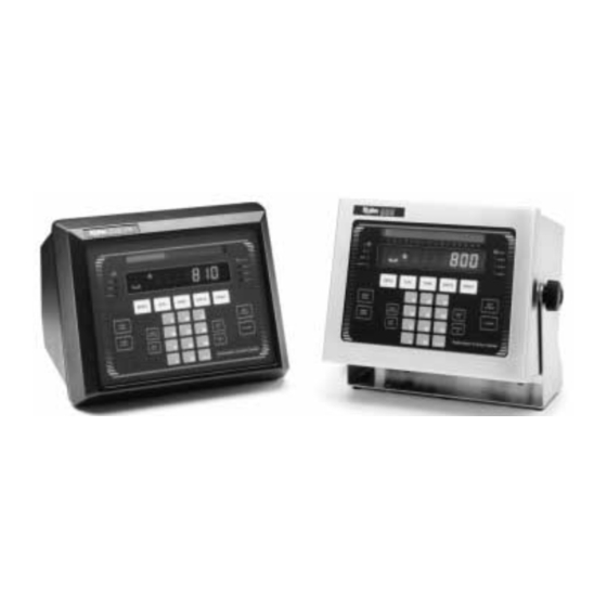
- Page 1 IQ plus 800 / 810 ® Digital Weight Indicator Installation/Operation Manual 30262...
-
Page 2: Table Of Contents
Modes 3, 4, 5, and 6 ..................5-4 Multiple scales ....................5-4 Individual Scale Setup ..................5-5 Copyright © 1997 Rice Lake Weighing Systems. All rights reserved. Printed in the United States of America. Specifications subject to change without notice. Rev. 3.0, March 1997... - Page 3 Auxiliary Serial Port ..................8-10 Remote Keyboard ..................... 8-12 Multiple Scale Inputs ..................8-13 2- and 4-Channel IQ plus 800 Relay Boards ............ 8-15 4- and 16-Channel IQ plus 810 Relay Racks ........... 8-16 Analog Output Modules ................... 8-19 Setpoint Digital Output Expander ..............8-22 Expanded Serial Communication ..............
- Page 4 Supervisor Setup Switch ................... 8-25 Start/Stop/Run Batching Switch ............... 8-26 Configuring the batching switch option ............8-27 IQ plus 800 Panel Mount Kit ................8-28 IQ plus 810 Panel Mount Kit ................8-29 Wall Mount Kit ....................8-30 Jetpak™ 100-Hz High Speed Option ............... 8-31 Allen-Bradley Remote I/O Interface ..............
-
Page 5: Section 1 Introduction
Introduction ABOUT THE MANUAL The IQ plus 800 and 810 indicators are both very flexible, offering a variety of standard features and optional features. This manual is organized so that you can learn about the basic installation and standard operations first, then find more detailed information about specific optional features in later sections (see Table 1-1 for optional features). - Page 6 Table 1-1. Applications Chart Optional Features IQ plus 800 IQ plus 810 DT IQ plus 810 SS IQ plus 810 HE Notes Rate of Change Function Peak Hold Function Bar Graph Passwords Dual-Channel Load Cell Input Module Setpoint Output Expander Module...
-
Page 7: Standard Features
• RS-485 communication option Application specialists at • Remote keyed switch for accessing supervisor mode Rice Lake Weighing Systems are available to help with unique • Panel mounting kit, or Wall mounting kit (standard on 800) situations not covered in this •... -
Page 8: Learning The Keyboard And Displays
DISP R.O.C. SCALE # DISP TARE SET POINT ENTER • TIME/DATE CLEAR Figure 1-2. IQ plus 810 DT and SS, and IQ plus 800 front panel Scale 1 Scale 2 Scale 3 Accum Scale 4 ZERO TARE UNITS PRINT DISP... -
Page 9: Keyboard Functions And Displays
Keyboard functions and displays The items in Table 1-4 describe various keys and display functions. Table 1-4. Numeric keypad These keys let you enter numerical data. Normally, you key a number, and then press ENTER and/or a function key. Each digit appears on the display screen as entered. - Page 10 Table 1-4. (continued) Disp Tare In the normal weighing mode, DISP TARE displays the current weight in the tare register (if any) and lights the “T” annunciator. In the Truck In/Out mode, key in a truck ID number and press DISP TARE.
-
Page 11: Annunciator Lights
Table 1-4. (continued) Set Point Press to access the current setpoint values. When you first press this key, the display shows “SP 1” for two seconds, then switches to show the setpoint value. Each time you press SET POINT, the next setpoint POINT (SP 2, SP 3, etc.) appears. -
Page 12: Installation
Installation MAKING POWER CONNECTIONS Caution ® The IQ plus 800/810 can operate from either a 110VAC or 220VAC To avoid damaging the 3-wire power supply line at 50 or 60 Hz. It is further recommended that the indicator, properly configure 800/810 be connected to an AC power supply that is on a separate branch or the power supply / display feeder from other AC equipment that causes step-load changes and/or other... -
Page 13: Wiring The Analog Inputs (Load Cells)
WIRING THE ANALOG INPUTS (LOAD CELLS) Wire the analog input cable from the load cell or junction box to the removable connector and plug into the CPU board at J10 near the A/D module. If your indicator was purchased after June 1, 1996, the A/D module will be surface mounted to the CPU board. - Page 14 Figure 2-3. IQ plus 810 DT wiring: side view NOTE: SERIAL COMM. WIRING The IQ plus 800 board locations J7-1 1-6, PRINT J7-2 PORT are the same for wiring purposes J7-3 SERIAL J7-4 CONN. J7-5 J7-6 J7-7 7-12, EDP J7-8...
- Page 15 Figure 2-4. IQ plus 810 DT wiring: top view 3-WIRE SUPPLY LINE REQUIRED The IQ plus 800 board locations are the same for wiring purposes SERIAL COMMUNICATIONS CABLE TO J7 GROUND LOAD CELL DIGITAL I/O CABLE TO J10 CABLE TO J4...
- Page 16 Figure 2-5a. IQ plus 800 side view NOTE: For wiring purposes, the board locations and terminal pinouts for the IQ plus 800 are identical to the IQ plus 810 Desktop model shown on pages 2-3 and 2-4. Figure 2-5b. IQ plus 800 top view...
- Page 17 For dual-channel A/D modules, there are jumper pins on the board near J10. The sense jumpers are labeled JP1–JP2 for channel one, and JP3–JP4 for channel two. Leave the jumpers installed for a 4-wire cable, and remove them for a 6-wire installation. See Table 2-1 for J10 analog input connec- tions.
-
Page 18: Wiring The Serial Communications Ports
WIRING THE SERIAL COMMUNICATIONS PORTS Terminal block J7 on the CPU board connects both the EDP (Electronic Data Processing) port and the printer port. You must configure these ports for your specific application (see Section 3, Configuration, for more information). The EDP port handles full-duplex RS-232 or simplex 20 mA current loop communication, with half-duplex RS-485 and full-duplex 20 mA current loop as optional features. -
Page 19: Continuous Output Serial Data Format
Continuous output serial data format When you select continuous transmission in the setup menus (SERIAL ® STREAM EDP, PRN, or AUX), the IQ plus 800/810 uses the Consolidated Controls serial data format as shown below: <STX> <POL> <wwwwwww> <UNIT> <G/N> <S> <TERM> NOTE: ASCII 02 G = Gross... - Page 20 (B) pins together. Table 2-5. RS-485 software • The controller software must be compatible with the IQ plus 800/810’s protocol. Some equipment may have its own, proprietary RS-485 protocol. • All equipment in the RS-485 network must follow the rules of half duplex communications: “Be quiet unless spoken to;”...
- Page 21 For example, with demand outputs, or in response to a KPRINT command, the protocol is: NOTE: <STX> <ADDRESS> <DEMAND DATA> <ETX> <CR> The EDP port supports bidirectional serial ASCII 02 ASCII 13 Response commands from communications. decimal decimal indicator: character character <first line>...
-
Page 22: Wiring The Digital Inputs And Outputs
WIRING THE DIGITAL INPUTS AND OUTPUTS The standard unit allows 3 digital inputs and 4 digital outputs. Wire any active digital inputs and outputs to connector J4 on the CPU board. See Table 2-6 for J4 digital I/O connections. Typically, digital outputs control relays which operate other equipment. Each output is a normally-open collector circuit, capable of sinking 250 mA when “on”... -
Page 23: Replacing The Battery
NOTE: REPLACING THE BATTERY You may lose important A 3.0V Lithium battery on the power supply / display board maintains the configuration parameters if you ® real-time clock and protects the system RAM when the IQ plus 800/810 is remove the battery when power not connected to the AC power line. -
Page 24: Board Diagrams
BOARD DIAGRAMS ® Use the following board diagrams to locate major components on the IQ plus 800/810 circuit boards. 1 2 3 4 5 6 7 (J10) Load Cell Connector (Terminal Screws on Back) (1st Load Cell Term) J9 (Factory Use Only) (2nd Load Cell Term) (J7) Serial Comm. -
Page 25: Configuration
When you move it to the that uses serial communication setup position, “CONFIG” appears on the display. “CONFIG” is one of to configure IQ plus 800/810 eleven main menu items, each with its own set of configurable parameters. indicators running standard indicator software. -
Page 26: Menu Charts
MENU CHARTS ® This section provides a graphic representation of the IQ plus 800/810 menu structure (Figure 3 through 3-11). In the actual menu structure, the settings you can choose under each parameter are arranged horizontally. To save page space here, each menu choice is shown arranged in vertical columns. - Page 27 Figure 3-3. Format menu CONFIG XXXXXXX SET ALG FORMAT SETPNTS SERIAL XXXXXXX P FORMT DIG IN XXXXXXX ALG OUT XXXXXXX BAR GRF CALIBRT XXXXXXX VERSION TOTAL SCALE 1 SCALE 2 SCALE 3 SCALE 4 DATE TIME PRIMARY SECNDRY RATECHG same as TOTAL TIMEFMT TIMESEP 12 HOUR...
- Page 28 Figure 3-4. Setpoints menu CONFIG XXXXXXX SET ALG FORMAT SETPNTS SERIAL XXXXXXX P FORMT DIG IN XXXXXXX ALG OUT XXXXXXX BAR GRF CALIBRT XXXXXXX VERSION SETPT 1 SETPT 2–20 same as SETPT 1 BATCHNG AUTO MANUAL Continuous or Batch setpoints continued GROSSSP NET SP...
- Page 29 Figure 3-4 (continued) Setpoints menu Batch setpoints PAUSE DELAY WAIT SS COUNTER AUTOJOG same as PAUSE same as COUNTER, but without NAME NAME NAME VALUE same as PAUSE VALUE ACCESS NAME DIGOUT NONE 0 thru 9 number number NONE NONE NONE 1 thru 16 0 thru 9...
- Page 30 Figure 3-5. Serial menu CONFIG XXXXXXX SET ALG FORMAT SETPNTS SERIAL XXXXXXX P FORMT DIG IN XXXXXXX ALG OUT XXXXXXX BAR GRF CALIBRT XXXXXXX VERSION PRINTER STREAM PRNDEST BAUD BITS BAUD BITS TERMIN EOL DLY TERMIN EOL DLY ADDRESS 4800 7 ODD CR/LF number...
- Page 31 Figure 3-6. Printer Format menu CONFIG XXXXXXX SET ALG FORMAT SETPNTS SERIAL XXXXXXX P FORMT DIG IN XXXXXXX ALG OUT XXXXXXX BAR GRF CALIBRT XXXXXXX VERSION GFMT NFMT TRWIN TRWOUT SPFMT At this level, you can View, Add same as GFMT Spaces, or Delete only.
- Page 32 Figure 3-7. Digital Input menu CONFIG XXXXXXX SET ALG FORMAT SETPNTS SERIAL XXXXXXX P FORMT DIG IN XXXXXXX ALG OUT XXXXXXX BAR GRF CALIBRT XXXXXXX VERSION DIGIN 1 DIGIN 2 DIGIN 3 same as DIGIN 1 ZERO TARE NT/GRS UNITS DSPTARE PRINT BATRUN...
- Page 33 Figure 3-9. Bar Graph menu CONFIG XXXXXXX SET ALG FORMAT SETPNTS SERIAL XXXXXXX P FORMT DIG IN XXXXXXX ALG OUT XXXXXXX BAR GRF CALIBRT XXXXXXX VERSION TWNKL DIGOUTS GRAPH GRPHALL SP REF BAND SP1 – SP20 number Figure 3-10. Calibrate menu CONFIG XXXXXXX SET ALG...
-
Page 34: Menu Descriptions
MENU DESCRIPTIONS Tables 3-1 through 3-11 provide complete information about each of the main menu options. Each table describes all parameters associated with that menu option, the choices available for each parameter, and a general description of each √ parameter and related choices. The system defaults are indicated by a check mark ( Table 3-1. - Page 35 Table 3-1 (continued). CONFIG menu (continued) . . . √ l i a s t r i t a i t a i t c i t a i t c i t a t a t l i a .
- Page 36 Table 3-1 (continued). CONFIG menu (continued) . . ) √ ± i t c i l a l i t . e l t - r c i l i t a e l i l l a , s l 1 √...
- Page 37 Table 3-2. SET ALG menu . . . 1 √ . s l . r o . l e i t p , l a o i t ® o i t i t p e l l h t i o l l .
- Page 38 Table 3-3. FORMAT menu ..l e . r a ) / ( — ) ; ( i t a . r e ) : ( ) , ( i t a . r e . . . i t c i s i i t a...
- Page 39 Table 3-3 (continued). FORMAT menu (continued) 1 √ i s i i s i . s t √ i t a . s t L √ . t h t a i √ i t a √ . t h t a i √...
- Page 40 Table 3-3 (continued). FORMAT menu (continued) 1 √ i s i i s i . t h √ i t a . s t √ . r e i s r s t i . s t √ s t i ®...
- Page 41 Table 3-4. SETPNTS menu √ – – . s t – . s t – . s t √ . e l s i l . t n l l i . t h ..t n l l i .
- Page 42 Table 3-4 (continued). SETPNTS menu (continued) n i t . . . l l i a l f P “ ” E i t n e t r i t n o i t : e t t s r n i t i f i .
- Page 43 Table 3-4 (continued). SETPNTS menu (continued) . s t . l a . t n , s s i t c l l i l a t t a i . t n i f i i t r l a t l l i l l a “...
- Page 44 Table 3-4 (continued). SETPNTS menu (continued) l a t . t u i t c l a t l l i – i t t s t i , t n √ . e r i t c c i t t s i s t f √...
- Page 45 Table 3-4 (continued). SETPNTS menu (continued) ) . . f i ( √ s i l √ – √ – s t l “ , ” . t r Configuration 3-21...
- Page 46 Table 3-5. SERIAL menu t t e , e t , s t i t a , s r i l - . s s t t e , e t s t i i t a i l - i l i t t e a i l...
- Page 47 Table 3-5 (continued). SERIAL menu (continued) √ . e t l a i . t r √ s t i . y t s t i t t i . t r √ . s r t t i l l i t t a t t a l a i...
- Page 48 Table 3-6. P FORMT menu (Note: For complete information, see page 9-6.) ..® 3-24 IQ plus 800/810 Installation Manual...
- Page 49 Table 3-7. DIG IN menu i t c , ) f e l i l l i ) f f l l i Table 3-8. ALG OUT menu . . s i t t . . s √ l l i .
- Page 50 Table 3-9. BAR GRF menu i t c , s t i t c . s t i t c t s r . y l l i t . t h i t c , s t i t c e l i i t c l i t...
- Page 51 Table 3-10. CALIBRT menu – i l a i t a . s t ..Table 3-11. VERSION menu i s r Configuration 3-27...
-
Page 52: Calibration
The IQ plus 800/810 stores calibration values in nonvolatile memory on the CPU board. You access these values through the CALIBRT setup menu. NOTE: If the IQ plus 800/810 has multiple scale inputs, you must do a weight Record all weight calibration calibration for each channel. - Page 53 FOR UNITS MANUFACTURED PRIOR TO JULY, 1996 Caution IQ plus 800/810 CPU boards manufactured prior to July, 1996 had separate A/D converters bolted to standoffs on their CPU boards. These replaceable Do NOT change any VOLTS...
-
Page 54: Operating Modes
Operating modes SETUP MODE The Setup Mode lets you access the configuration and calibration param- eters (as described in Section 3, Configuration). To enable this mode, open the case and move switch SW1 on the CPU board. See Figure 2-3 in Section 2, Installation, for location of the setup switch. -
Page 55: Truck In/Out Modes
TRUCK IN/OUT MODES CONFIG 200TARE MODE 1 MODE 2 MODE 3 MODE 4 MODE 5 MODE 6 The truck in/out modes handle multiple truck ID numbers and tare weights. There are six modes which allow you to combine features in various ways (see Table 5-1). -
Page 56: Selecting A Mode
Selecting a mode To select a truck in/out mode (as in diagram below), move setup switch SW1 to the CONFIG position (see Setup Mode on page 5-1 ). Then, press TIME/DATE once to drop to the next level. Press CLEAR NOTE: several times until the display reads 200TARE. -
Page 57: Modes 3, 4, 5, And 6
NOTE: 6. Key in the ID number (from the weigh-in ticket) and press PRINT. The indicator prints the following weigh-out ticket and automati- If you key in an ID number that is already in memory, the cally clears the information from memory: display reads “BAD ID”... -
Page 58: Individual Scale Setup
INDIVIDUAL SCALE SET-UP The IQ plus 810 offers up to four scale inputs with the flexibility to define different graduation sizes for all the individual scales. Many of the param- eters defining the functionality of the channel can be defined individually for each channel. - Page 59 Example: If the scales have the following settings: SCALE#1: GRADS=2000 DEC PNT=8888880 DSP DIV=5 ==> COUNT BY 50 SCALE#2: GRADS=100000 DEC PNT=888888.8 DSP DIV=1 ==> COUNT BY .1 TOTAL: GRADS=110000 DEC PNT=8888888 DSP DIV=5 ==> COUNT BY 1 NOTE: The number of grads for the The number of grads for the total channel is calculated as follows: total channel is not user- ((GRADS#1 x COUNTBY#1) + (GRADS#2 x...
- Page 60 • OVERLOAD - When any individual channel is above OVER- LOAD or below UNDERLOAD, the total channel display is also blanked. • PKHOLD - If the peak hold feature is enabled, PKHOLD is set globally for all channels. The peak value for a channel is only being calculated while the channel is being displayed.
-
Page 61: Key Press Commands
The EDP (electronic data processing) port lets you control the IQ plus 800/810 from a remote keyboard or personal computer. You can transfer configuration data directly between two IQ plus 800/810 indicators. By using special commands from the keyboard, you can simulate front panel key press functions, call up current settings for setup parameters, and perform reporting functions. - Page 62 Table 6-1 (continued). Key press commands (continued) ’ . ‘ After the indicator receives a key press command, it responds with the message “OK”. The “OK” response verifies that the command was received. However, this response does not indicate that a requested action was completed.
-
Page 63: Reporting Commands
An example of using the EDP commands is as follows: To enter a 15-pound tare weight using EDP commands — 1. Type K1 and press ENTER (or RETURN ). 2. Type K5 and press ENTER. 3. Type KTARE and press ENTER. 4. -
Page 64: Special Function Commands
SPECIAL FUNCTION COMMANDS There are four special function serial commands available (Table 6-3). The commands, RESETCONFIGURATION and CLEARALLFEATURES, are accessible from the setup mode only. Table 6-3. Special function commands i t c NOTE: t n i t s i r e t i t t The indicator must be in Setup... - Page 65 Table 6-4. CONFIG commands (Note: Indicator must be in Setup Mode to change.) i t a l a t t l i , h t . r e Table 6-5. SET ALG commands (Note: Indicator must be in Setup Mode to change.) .
- Page 66 Table 6-6. FORMAT commands (Note: Indicator must be in Setup Mode to change.) i s i , 8 . . s t i s i , 8 . . s t . r e . t n , 8 . .
- Page 67 Table 6-7. SETPNTS commands . r e – . t n . s i . t c . l e l a t . t u – i t a – . e r . t n – . s s .
- Page 68 Table 6-8. SERIAL commands . e t s t i . y t i t a . s r . s s . e t s t i . y t i t a . s r a i l .
- Page 69 Table 6-9. P FORMT commands . y l i t c s t i *** Version 3.0 and later software. Table 6-10. DIG IN commands a t i a t i a t i Using the EDP port...
- Page 70 Table 6-11. ALG OUT commands i l a i t a i l a i t a Table 6-12. BAR GRF commands – Table 6-13. CALIBRT commands s t l i l a s t l . e t s t l i l a s t l .
-
Page 71: Transmit Weight Data Commands
TRANSMIT WEIGHT DATA COMMANDS The serial transmit weight data commands (Table 6-14) transmit data out the EDP port on demand. They allow you to request weight data from any of the active channels via the EDP port. These commands are accessible while in the operating mode. -
Page 72: Printing Setpoints
Printing setpoints 1. Make sure a compatible printer is properly configured and installed on the EDP port. 2. Place the indicator in supervisor mode and press PRINT (see Section 2, Installation, for more information on installing a remote supervisor switch). 3. -
Page 73: Transferring Configuration Data Directly Between Two Indicators
Hotline™ is an optional computer software program which makes it easy to establish, save, change, and transfer configuration data—including setpoints for batch processing. It is available from Rice Lake Weighing Systems. Following are some common questions and answers about Hotline:... - Page 74 Hotline saves the configuration settings you’ve established as a file, which it can copy to any IQ plus 800/810 indicator. You can save the file for future use, or modify it to create additional configuration files.
-
Page 75: Setpoints And Batch Processing
Setpoints and batch processing OVERVIEW NOTE: The IQ plus 800/810 indicators have 20 programmable setpoints, each with It is possible to configure 20 unique parameter selections. These parameters determine exactly how a setpoints without using the front setpoint functions. To configure the setpoints, you must enter the setup panel keys. -
Page 76: Setpoint Menu Chart
Setpoint menu chart Figure 7-1 is a graphic overview of the setpoint menu structure. See Section 3, Configuration, for more information. SETPNTS Global parameter SETPT 1 SETPT 2–20 same as SETPT 1 BATCHNG Continuous or Batch setpoints GROSSSP NET SP +REL SP –REL SP %REL SP... -
Page 77: Using Continuous Setpoints
USING CONTINUOUS SETPOINTS Continuous setpoints are free-running—the indicator is constantly checking the input channel for the setpoint value at each A/D update. If the input channel weight reading matches the setpoint value, the indicator acts upon the corresponding digital output (logic = active-low). NOTE: Some continuous setpoints do not require a numerical value. -
Page 78: Using Batched Setpoints
Batched setpoints are active one at a time, in an ordered sequence. Since there are 20 setpoints, the IQ plus 800/ 810 can control up to 20 separate batch processing steps or operations. When a batch setpoint is active, the corresponding digital output turns ON for the duration of the setpoint (batch step). -
Page 79: Front Panel Preact Value Access
FRONT PANEL PREACT VALUE ACCESS Values for the setpoint parameter PREACT can be viewed on the front panel, while in the normal operating mode if the PREACT parameter has been turned ON . The SET POINT key function allows you to access the PREACT value if the ACCESS parameter is set to ON and PREACT is not NOTE: OFF. -
Page 80: Assigning The Names To Setpoints
Table 7-3. Setpoint name defaults Name... Default... SPNAME#0 INGRED1 SPNAME#1 INGRED2 SPNAME#2 INGRED3 SPNAME#3 INGRED4 SPNAME#4 INGRED5 SPNAME#5 INGRED6 SPNAME#6 INGRED7 SPNAME#7 INGRED8 SPNAME#8 INGRED9 SPNAME#9 INGRD10 Assigning the names to setpoints The setpoint parameter NAME allows you to assign names to setpoints. NAME can be set to the SPNAME number 0,1,2,...9, as shown above. -
Page 81: Optional And Advanced Standard Features
Optional and advanced standard features APPLICATIONS CHART Table 8-1 is a list of all the IQ plus 800/810 optional and advanced standard features discussed in this section. Table 8-1. Applications Chart Optional and Advanced Features IQ plus 800 IQ plus 810 DT... -
Page 82: Rate Of Change Function
RATE OF CHANGE FUNCTION (OPTIONAL) NOTE: The IQ plus 800/810 — with the Rate of Change (ROC) function activated An access number is provided and in the normal weighing mode — will display a change in weight over a when this option is purchased. -
Page 83: Accumulate Function
ACCUMULATE FUNCTION (STANDARD FEATURE) The Accumulate function (represented by the PSHACCUM submenu, under the SETPNTS menu) is used to add weight data to a register for later access To verify that the accumulate by the user. The accumulator can keep a running total of weights entered function is installed, press the either automatically by the setpoints, or manually by a user pressing the DISP ACCUM key. -
Page 84: Front Panel Access
ACCUM #x aaaaaaa LB 01/01/94 09:20 where x is the accumulator number and aaaaaaa is the updated accumu- lator value. IQ plus 800/810 Installation Manual... -
Page 85: Peak Hold Function
The ticket produced by the setpoint PSHACCM is not formattable. Some customers do not want this information printed so the following parameter settings for PSHACCUM have been added: 1 QUIET, 2 QUIET, 3 QUIET, 4 QUIET, and 0 QUIET. By setting the PSHACCM setpoint parameter to one of these settings, the corresponding accumula- tor will be updated but the accumulator print ticket will be suppressed. -
Page 86: Bar Graph
When the ingredient begins to fill, all of the bar graph segments will be OFF. The segments will begin to light from left to right as the weight value increases to meet the setpoint value. IQ plus 800/810 Installation Manual... - Page 87 XXXXXXX BAR GRF TWNKL DIGOUTS GRAPH GRPHALL Figure 8-3. Bar Graph SP REF BAND submenu layout SP1 – SP20 number Another popular use for the bar graph in “GRAPH” mode is as an “over/ under” indicator. In this application the low level is set at one end of a band NOTE: width and the high level is set at the other end.
-
Page 88: Passwords
Backdoor password If you forget the CONFIG password and have no way to enter the CONFIG menu, call Rice Lake Weighing Systems. We can help you find a unique “back-door” password to enter the CONFIG menu. IQ plus 800/810 Installation Manual... -
Page 89: Expansion Board
EXPANSION BOARD (OPTIONAL) The IQ plus 810 Expansion Board (Figures 8-5 through 8-7) is a separate hardware board which provides the additional room for adding other options to the system. The expansion board mounts directly in back of the main board on furnished standoffs. -
Page 90: Auxiliary Serial Port
9600, rather than 19200, and is simplex output only. SERIAL PRINTER STREAM PRNDEST Figure 8-8. Auxiliary serial port parameter layout BAUD BITS TERMIN EOL DLY ADDRESS 2400 7 ODD CR/LF number number 1200 8 NONE 7 EVEN 9600 4800 8-10 IQ plus 800/810 Installation Manual... - Page 91 When configured for RS-232 applications through the AUX port, neither of the integrated chips U7 nor U8 (Figure 8-9) is installed in their respective sockets on the expansion board. J4-5 (OUT) and J4-6 (GND) terminal connections are used for output-only RS-232 communication. Output-only 20 mA Current Loop transmission is also available simultaneously on J4-4 (20 mA CL-) and J4-6 (20 mA CL+ ).
-
Page 92: Remote Keyboard
J5-30 DISP ACCUM J5-12 4 J5-31 5 J5-13 6 J5-32 DISP RO J5-14 7 J5-33 8 J5-15 9 J5-34 TIME/DATE (Down) J5-16 .(Decimal Point) J5-35 0 J5-17 ENTER J5-36 GROUND J5-18 GROUND J5-37 nc J5-19 nc 8-12 IQ plus 800/810 Installation Manual... -
Page 93: Multiple Scale Inputs
MULTIPLE SCALE INPUTS (OPTIONAL) The standard IQ plus 800/810 has a single analog input channel. The 800 can be expanded to 2 channels, and the 810 to 2, 3, or 4. This feature is represented by the CHANS submenu, under the SET ANALOG menu. The parameter settings (or channel selections enabling multiple channel inputs) are accessible from the CHANS submenu. - Page 94 (on module). Go to the expansion board will not be available after August, 1996. Calibrate-Volts submenu on the IQ plus 800/810 to enter these • Single-channel module on main board, and dual-channel module on values. (Refer to Section 4,...
- Page 95 2- AND 4-CHANNEL RELAY BOARDS (IQ PLUS 800) A 2-channel or a 4-channel relay board is available for mounting inside the IQ plus 800 case. Relay Board Figure 8-12. Mounting relay boards on IQ plus 800 back panel 2-Channel Relay Board This compact (2.5"...
- Page 96 VDC power supply be used to operate relays. CPU Board Figure 8-15. Mounting of 4-channel A/D Converter relay racks on SS or HE panel Mounting holes for second 4-channel relay rack Mounting holes for 16-channel relay rack 8-16 IQ plus 800/810 Installation Manual...
- Page 97 J4 CONNECTOR ON MAIN BOARD DIGOUT 1 AC OUTPUT 4 TO EQUIPMENT DIGOUT 2 OAC5 OUT DIGOUT 3 AC OUTPUT 3 DIGOUT 4 TO EQUIPMENT OAC5 OUT DIGIN 3 AC OUTPUT 2 DIGIN 2 TO EQUIPMENT OAC5 OUT DIGIN 1 AC OUTPUT 1 TO EQUIPMENT OAC5 OUT...
- Page 98 Boards manufactured prior to that date must use the separate 5 VDC power supply to energize the relay board. In either case, run a 5 VDC ground wire to J4-8 or J4-9. Figure 8-18. 16-channel relay rack with external 5 VDC power supply 8-18 IQ plus 800/810 Installation Manual...
-
Page 99: Analog Output Modules
ANALOG OUTPUT (OPTIONAL) The IQ plus 800 may have one analog output module installed. The IQ plus 810 will accept two analog output modules with the expansion board assembly. Either output may be setup for 0 to 10V, or for 4 to 20-mA analog output. - Page 100 The values that you will use for the coarse span values are: 15300 For 0 to 10 Volt Output 12400 For 4 to 20 milli-amp Output You simply divide the proper number from above by the full span weight value. 8-20 IQ plus 800/810 Installation Manual...
- Page 101 As an example of this, we will calculate the coarse span value for a 0 to 10V output at 5000 lb. In this case, we will use the value of 15300 for the 0 to 10V output and divide it by the full scale output of 5000. 15300/5000 = 3.06 This calculation gives us a coarse span value of 3.06.
-
Page 102: Setpoint Digital Output Expander
1 – 4 remain on the J4 terminal J5-4 DOUTCLK of the main board, and 5 – 16 are on the J1 terminal of the J5-5 SDOUT setpoint expander board. J5-6 J5-7 HGND J5-8 HGND 8-22 IQ plus 800/810 Installation Manual... -
Page 103: Expanded Serial Communication
EXPANDED SERIAL COMMUNICATION (OPTIONAL) The expanded serial communications option includes: • Adding duplex 20 mA current loop to EDP serial port • Adding RS-485 to EDP serial port Adding duplex 20 mA current loop to EDP serial port In standard form, the EDP port has duplex RS-232 serial and simulta- neous output-only 20 mA current loop (CL) communication. -
Page 104: Communications For Auxiliary Port
U8 is not installed. Terminal J4 on the expansion board is used for the AUX serial port connections. J4-1 (RS-485-A) and J4-2 (RS-485-B) are used for RS-485 applications. See the connector pinout table following. 8-24 IQ plus 800/810 Installation Manual... -
Page 105: Supervisor Setup Switch
AUX port RS-485 wiring AUX Port RS-485 (U7)* J4-1 485-A J4-2 485-B J4-3 J4-4 J4-5 J4-6 *Integrated Chip U7 must be installed; U8 must NOT be installed. J4 (AUX PORT) Figure 8-24. Location of RS-485 chip, U-7, on component side of expansion board SUPERVISOR SETUP SWITCH (OPTIONAL) Factory-Installed J8 Jumper... -
Page 106: Start/Stop/Run Batching Switch
Figure 8-27 on the following ABORT START page. Each switch requires a separate digital input, leaving one of the IQ plus 800/810’s original three digital inputs available for other use. The 5-VDC digital ground required to operate the switches is available on the indicator’s digital input terminal at J4-... -
Page 107: Configuring The Batching Switch Option
ABORT/RUN/START SWITCH BLACK GREEN J4-MAIN BOARD DIG OUT 1 DIG OUT 2 DIG OUT 3 DIG OUT 4 Figure 8-27. Wiring diagram for DIG IN 3 start/stop/run batching switch DIG IN 2 WHITE GREEN DIG IN 1 BLACK 5 VDC STOP/START MUSHROOM SWITCH Configuring the batching switch option When the hardware switches and wires are completed, place the... -
Page 108: Iq Plus 800 Panel Mount Kit
If the tilt stand has been attached, remove it from the indicator and discard the large thumbscrews which held the tilt stand to the indicator. Insert the IQ plus 800 completely into the panel cutout until the front lip of the indicator contacts the gasket. -
Page 109: Iq Plus 810 Panel Mount Kit
IQ PLUS 810 PANEL MOUNT KIT (OPTIONAL) The panel mounting kit for the IQ plus 810 Desktop model contains five screws with washers which replace the original screws holding the body to the faceplate. A template constructed from the drawing below may be used to mark the hole cutout in the panel. -
Page 110: Wall Mount Kit
Overall dimensions are shown in Figures 8-33 and 8-34. 6.28 6.32 Figure 8-33. Wall/tilt stand (side view) 6.34 9.48 6.78 Figure 8-34. Wall/tilt stand (front view) 8-30 IQ plus 800/810 Installation Manual... - Page 111 100-HZ HIGH SPEED OPTION (OPTIONAL) The Jetpak™ version of the IQ plus 800/810 features an update rate of 100 updates per second. This option can be added after purchase to modify an existing unit, but it is best that it be initially ordered as a high-speed unit.
-
Page 112: Allen-Bradley Remote I/O Interface
ALLEN-BRADLEY ® REMOTE I/O INTERFACE (OPTIONAL) The Remote I/O Interface allows IQ plus 800/810 indicators to communicate ® ™ ® with PLC and SLC controllers using the Allen-Bradley Remote I/O network. The Remote I/O Interface returns weight and status information streamed from the indicator to the PLC controller and provides full control of indicator function to the PLC programmer. -
Page 113: Recipe Storage Option
RECIPE STORAGE OPTION This option provides nine “stored” recipes and one “working” recipe. Each recipe has 16 setpoints. You can configure all nine working recipies from the “SETPNTS” configuration submenu or by using EDP commands. Also, you can copy a stored recipe into the currently running “working” recipe from the front panel or with EDP commands. - Page 114 Otherwise, Type 1 is implemented. The maximum number of Type 2 concurrent setpoints is five. SETPNTS RECIPE1 SETPT 1 CONCUR GROSSSP –GROSS –NET BATCHPR VALUE START DIGOUT Enter value Scroll to Scroll to Scroll to with keybd. value value value 8-34 IQ plus 800/810 Installation Manual...
-
Page 115: Appendix
Appendix SPECIFICATIONS Analog Specifications Full Scale Input Signal 5 to 39 mV including deadload (initial load) Analog Signal Input Range 0.6 mV/V - 3.9 mV/V Analog Signal Sensitivity 0.3 microvolts/graduation minimum, 1.0 microvolt/grad recommended Input Impedance > 10 MΩ 0.3 µV p-p with 2 Hz analog filter, digital filter 4 Noise (Referred to Input) Internal Resolution Selectable: 300,000 - 740,000 counts... - Page 116 12 VA with minimum configuration, 30 VA with all options Fusing 120 VAC operation: 0.25 A Slo-Blo radial lead subminiature fuse (RLWS part #35993) 240 VAC operation: 0.125 A Slo-Blo radial lead subminiature fuse (RLWS part #35994) IQ plus 800/810 Installation Manual...
- Page 117 Environmental Operating Temperature –10 to +40°C (legal operating range) –10 to +50°C (industrial operating range) Storage Temperature –25 to +70°C, limited by battery life Electric Field Rejection Per SMA requirements Emissions FCC Part 15 Class A, UL 466, UL 508 and CISPR 22 Class A Electrical Safety According to IEC 950, UL 1950, CSA 220...
-
Page 118: Filter Selections
The selections from 1 to 128 reflect the number of readings averaged per update period. When a reading is encountered that is outside a predetermined band, the averaging is overridden, and the display “jumps” directly to the new value. IQ plus 800/810 Installation Manual... - Page 119 ™ Advanced Rattletrap digital filtering (selections with RT after the number) indicate a mode that can be viewed as a hybrid combination of the best features of analog and digital filtering. RATTLETRAP™ uses a vibration-dampening algorithm developed in actual industrial applica- tions with extreme vibration present.
-
Page 120: Custom Print Formatting Procedure
This feature allows the user to customize the Demand Print serial output to meet the needs of the user. With this feature, the IQ plus 800/810 can be setup to print special informa- tion such as company name and address, scale identification information, etc. -
Page 121: Manipulating Format Strings
For example, to check the current configuration of the Gross Demand printout, you can enter: “GFMT” then press ENTER or RETURN The IQ plus 800/810 will then respond by sending the current configu- ration for the Demand Gross Printout which will look something like this: GFMT=SCALE#<S><NL2>GROSS<G><NL2><TD><NL>... - Page 122 NOTE: (SETPOINT key), the user will see For more information on the character with the new ASCII code entered. changing print format from the front panel of the IQ plus 800/ 810, see page 3-7. IQ plus 800/810 Installation Manual...
-
Page 123: Gross/Net Demand Ticket
Toggle weight data normal format and no format** * If the number (x) is missing 1 is assumed. ** After receiving this command the IQ plus 800/810 will send all succeeding weight data unformatted. Unformatted means no leading spaces, no decimal place, and no trailing characters. - Page 124 See the example below. Example: GFMT=SCALE#<S><NL><G>GROSS<NL>ID#<ID><NL2><TD><NL> This string will produce the following ticket: SCALE# 1 xxxxxxxx LB GROSS ID# aaaaaaa 11:11 01/01/94 where xxxxxxxx is the current gross weight and aaaaaaa is the current ID number. 9-10 IQ plus 800/810 Installation Manual...
-
Page 125: Truck Weigh-In And Weight-Out Tickets
Truck weigh-in and weight-out tickets You can use the TRWIN and TRWOUT format strings to customize the truck weigh-in and weight-out tickets. The strings are handled the same way the GFMT/NFMT strings are handled, except the list of commands includes different data. Table 9-3 is a list of the commands you can use to configure truck print tickets. -
Page 126: Setpoint Push Print Ticket
In the case of relative setpoints, relative value is printed. ** If the number (x) is missing assume 1. *** After receiving this command, the IQ plus 800/810 will send all succeeding weight data unformatted. “Unformatted” means no leading spaces, no decimal place, and no trailing characters. -
Page 127: Conversion Factors For Secondary Units
CONVERSION FACTORS FOR SECONDARY UNITS The IQ plus 800/810 has the capability to mathematically convert a weight into many different types of units and instantly display those results with a press of the UNITS key. In the 1st level menu, FORMAT, the primary units display can be converted with a multiplier into many possible forms for display as secondary units. - Page 128 Inches of mercury at 0°C 0.8826 1.133 Feet of water at 4°C Kg per square meter 304.8 3.281 x 10 Feet of water at 4°C Pascals 2.989 x 10 3.346 x 10 - 1 5 Fermis Meters 9-14 IQ plus 800/810 Installation Manual...
- Page 129 Table 9-5. Conversion Factors (continued) To Convert Into Multiply By Conversely x By Foot candles 10.764 0.0929 Foot lamberts Candelas per sq meter 3.4263 0.2918 Foot-pounds Gram-centimeters 1.383 x 10 1.235 x 10 Foot-pounds Horsepower-hours 5.05 x 10 1.98 x 10 Foot-pounds Kilogram-meters 0.1383...
- Page 130 Dynes per square cm 6.8946 x 10 1.450 x 10 Pounds per square in Pascals 6.895 x 10 1.45 x 10 Poundals Dynes 1.383 x 10 7.233 x 10 Poundals Pounds (avdp) 3.108 x 10 32.17 9-16 IQ plus 800/810 Installation Manual...
- Page 131 Table 9-5. Conversion Factors (continued) To Convert Into Multiply By Conversely x By Quadrants Degrees 11.111 x 10 Quadrants Radians 1.5708 0.637 Quarts (U.S. dry) Cubic cms 1101.4 9.9079 x 10 Quarts (U.S. liquid) Cubic cms 946.4 1.057 x 10 Radians Mils Radians...
- Page 132 Ctrl ^ «i Ctrl _ ƒ space 32 á ß í “ ó ú ñ Ñ & µ ° ¿ ® ÿ ¡ ˆy ± «A ˆÅ © " « < ¢ > ¥ 9-18 IQ plus 800/810 Installation Manual...
-
Page 133: Error Messages
Make sure volts calibration values are correct. Check the software revision. In older versions with multiple scale applications, the display blanks when any scale goes over or under range. Call Rice Lake Weighing Systems for assistance. A/D CONVERTER OUT OF RANGE Appendix... -
Page 134: Software Revision History
The unit will blank, however, if one scale goes into an underrange condition. The following parameters can be changed “on the fly” by keying in the correct EDP commands without the need to enter the SETUP mode: BARGRF, BARBAND. (continued) 9-20 IQ plus 800/810 Installation Manual... - Page 135 GRPHALL mode. New motion band settings of 2, 20, and OFF have been added. New Tare Function — In past versions the IQ plus 800/810 has had a parameter called GONLY which would allow or disallow Tares to be entered. The GONLY parameter has now been replaced with the TAREFN (Tare Function) parameter.
-
Page 136: Limited Warranty
IQ plus 800/810 LIMITED WARRANTY Rice Lake Weighing Systems (RLWS) warrants that all RLWS equipment and systems properly installed by a Dis- tributor or Original Equipment Manufacturer (OEM) will operate per written specifications as confirmed by the Distributor/OEM and accepted by RLWS. All systems and components are warranted against defects in materials and workmanship for one (1) year. - Page 137 BATRUN, batching proceeds as if BATRUN were installation site that much always on. See page 5 for more information. easier. Watch for the new IQ plus 800 enclosures to start shipping in August 1997. See Tech Talk Volume 15 for more information about the new enclosure.
-
Page 138: Front Panel Keys And Leds
TECH TALK A TECHNICAL PRODUCT PUBLICATION Front Panel Keys and LEDs • In Release 3.11, analog outputs are set off (0 VDC or 4 mA) when the indicator is placed in setup mode. Lb/Kg LEDs • New parameters added for Release 3.11 (LGLMODE on the CONFIG menu, UNITS and SPNAME on the In software versions prior to Release 3.11, the Lb and Kg FORMAT menu) cannot be set using the Hotline™... - Page 139 TECH TALK A TECHNICAL PRODUCT PUBLICATION CONFIG XXXXXXX SET ALG FORMAT SETPNTS SERIAL P FORMT XXXXXXX DIG IN ALG OUT XXXXXXX BAR GRF XXXXXXX CALIBRT VERSION XXXXXXX PWRUPMD SCALE 1 SCALE 2 SCALE 3 SCALE 4 TARE200 PK HOLD TARE FN LGLMODE CONSNUM PASSWRD...
- Page 140 TECH TALK A TECHNICAL PRODUCT PUBLICATION UNITS Parameter SERIAL Menu The UNITS parameter allows units identifiers to be An optional parameter, ABSTRM, is added between the customized. Default identifiers (LB-KG-OZ-TN-GR-G) can STREAM and PRNDEST parameters to allow selection of be changed using the procedure described under the P the port used for streaming to the Remote I/O Interface FORMT menu.
-
Page 141: Setpoint Processing
TECH TALK A TECHNICAL PRODUCT PUBLICATION Setpoint Processing ALARM Parameter for Batch Setpoints The ALARM parameter is redefined for batch setpoints in Automatic Reset for COUNTER Setpoints Release 3.11 to hold the alarm message active until the The counter setpoint is changed in Release 3.11 to setpoint is satisfied. -
Page 142: Truck Modes
TECH TALK A TECHNICAL PRODUCT PUBLICATION Resetting ID, Consecutive Number, and Accumulator • Digital outputs set in two consecutive batch setpoints no longer toggle off and back on between setpoints. Values for Print Commands • The default values for DIGIN 1 and DIGIN 2 are ID, consecutive number, and accumulator values can be reset by specifying the value directly on the print format changed for Release 3.11. - Page 143 TECH TALK A TECHNICAL PRODUCT PUBLICATION BATSTATUS The BATSTATUS command is used to check the current status of various setpoint and batching conditions. BATSTATUS returns 14 bytes of status data as described in Figure 8 (below). Status information returned in bytes 3–12 is coded as ASCII characters @ (hex 40) through O (hex 4F); only the low order bits of these characters are significant.
- Page 144 TECH TALK A TECHNICAL PRODUCT PUBLICATION CONFIG XXXXXXX SET ALG FORMAT SETPNTS SERIAL P FORMT XXXXXXX DIG IN ALG OUT XXXXXXX BAR GRF XXXXXXX CALIBRT VERSION XXXXXXX GFMT NFMT TRWIN TRWOUT SPFMT same as GFMT View character string/edit active Use SETPOINT and CLEAR keys to scroll left or right in character character DISP...
Need help?
Do you have a question about the IQ plus 800 and is the answer not in the manual?
Questions and answers