
Subscribe to Our Youtube Channel
Related Manuals for Rice Lake 320IS Plus


Summary of Contents for Rice Lake 320IS Plus
- Page 1 320IS Plus Intrinsically Safe Digital Weight Indicator Version 2.0 Installation Manual 85353...
- Page 3 2.3 Hazardous Area Installation of the 320IS Plus ....... . .
- Page 4 RS-485 Communications ............62 320IS Plus Plus Installation Manual...
- Page 5 9.10 320IS Plus Specifications ........
-
Page 7: Introduction
(six-wire remote sense specifically listed in this manual or control drawing recommended) PN 72717 as part of the Rice Lake Factory Mutual • Full-duplex fiber optic interface to attach an systems approval. Failure to comply with this voids external I/O board located in the safe area the FM approval. -
Page 8: Operating Modes
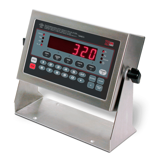
In setup mode, the keys are used to navigate through menus, select digits within numeric values, and increment/decrement values. See Section 3.1.3 on page 14 for information about using the front panel keys in setup mode. Figure 1-1. 320IS Plus Front Panel 320IS Plus Installation Manual... - Page 9 Display Mode Normal Setup Test Count Key Functions Turn the indicator on or Turn the indicator on or Turn the indicator on or Turn the indicator on or Batch start Batch stop Return gross weight • Move up (vertically) Exit display to zero •...
-
Page 10: Led Annunciators
• If the primary unit is short tons (tn) and the secondary unit is pounds (lb), the LED is lit for primary units (tn), and is lit for secondary units (lb). Because there is no LED for short tons, the LEDs are used as primary and secondary units annunciators. 320IS Plus Installation Manual... -
Page 11: Indicator Operations
/ kg lb / kg Table 1-2. Unit Annunciators, Primary/Secondary LEDs Used For All Configurations Indicator Operations Basic 320IS Plus operations are summarized below. 1.5.1 Toggle Gross/Net Mode Press the key to switch the display mode from gross to net, or from net to gross. If a tare value has GROSS/NET been entered or acquired, the net value is the gross weight minus the tare. -
Page 12: Display Part Weight
• To display the current accumulator value, press the key. ACCUM • To clear the accumulator, press to show the current value, then press the key twice to ACCUM CLEAR reset the accumulator. 320IS Plus Installation Manual... -
Page 13: Installation
The indicator should be powered by an FM-approved indicator with attached tilt stand, this manual, and a Rice Lake power supply or alternatively from an parts kit. If any parts are missing or were damaged in external battery pack. The power requirements of the... -
Page 14: Ac Power Wiring
The recommended initial battery charge time is 14 hours. NOTE: See Battery Charging Instruction Sheet (PN 96567) for instructions on chargng the battery. 320IS Plus Installation Manual... -
Page 15: Cable Connections And Installation
The following sections contain information on cable 5. Insert cable and reducing gland into cord grip connections and installation for the 320IS Plus stem. Intrinsically safe cables are specified by NOTE: control drawing. All cables must have appropriate 6. -
Page 16: Load Cells
CN3 as shown in Figure 2-8 on page 12. If using 6-wire load cell cable (with sense wires), remove jumpers J1 and J2 before installing connector CN3. For four-wire installation, leave jumpers J1 and J2 on. Figure 2-5. CN3 Load Cell Connections 320IS Plus Installation Manual... -
Page 17: Fiber Optics Installation
G r o u n d l u g The fiber optics port is located on the indicator CPU board (see Figure 2-8 on page 12). Figure 2-7. 320IS Plus Enclosure Backplate 2.5.1 Assembling Fiber Optics Connectors Use the following steps for assembling the fiber optic... - Page 18 Figure 2-8. 320IS Plus CPU Board Part Number Description (Quantity) Part Number Description (Quantity) 4 in. W/No. 8 Ground Wire 8–32NC Hex Kep Nut 45043 14626 16492 Earth Ground Label 19538 1.25 x 1 Slotted Black Post 15627 PG–9 Metal Lock Nut 91852 PG–9 Metal Cord Grip...
-
Page 19: Configuration
Configuration To configure the 320IS Plus indicator, the indicator Revolution III supports both uploading and must be placed in setup mode. The setup switch is downloading of indicator configuration data. This accessed by removing the large fillister head screw on capability allows configuration data to be retrieved the enclosure backplate. -
Page 20: Front Panel Configuration
Configure analog output. See Section 3.2.8 on page 31 for analog output configuration. VERS Version Display installed software version number. Table 3-1. 320IS Plus Menu Summary SERIAL, PFORMT, SETPNT, DIG IN, and ALGOUT menu functions require fiber optics NOTE communications with I/O module to operate. -
Page 21: Menu Structures And Parameter Descriptions
(see Figure 3-4). Menu Structures and Parameter Descriptions The following sections provide graphic representations of the 320IS Plus menu structures. In the actual menu structure, the settings you choose under each parameter are arranged horizontally. To save page space, menu choices are shown in vertical columns. -
Page 22: Configuration Menu
1–100 000 and should be consistent with legal requirements and environmental limits on system resolution. To calculate GRADS, use the formula, GRADS = Capacity / Display Divisions. Display divisions for primary and secondary units are specified on the FORMAT menu. Table 3-2. Configuration Menu Parameters 320IS Plus Installation Manual... - Page 23 CONFIG Menu Parameter Choices Description ZTRKBN Zero track band. Automatically zeroes the scale when within the range specified, as long 0.5D as the input is within the configured zero range (ZRANGE parameter). Selections are ± display divisions. Maximum legal value varies depending on local regulations. ZRANGE 1.9% Zero range.
-
Page 24: Format Menu
DECPNT Level 3 submenu parameter descriptions. DSPDIV SECNDR UNITS Specifies the decimal position, display divisions, units, and conversion multiplier used for MULT the secondary units. See Level 3 submenu parameter descriptions. Table 3-3. Format Menu Parameters 320IS Plus Installation Manual... - Page 25 FORMAT Menu Parameter Choices Description DSPRAT 250MS Display rate. Sets the update rate for displayed values. Values are in milliseconds (MS) or 500MS seconds (SEC). 750MS 1SEC 1.5SEC 2SEC 2.5SEC 3SEC 4SEC 6SEC 8SEC Level 3 Submenus UNITS Specifies primary unit for displayed and printed weight. Values are: LB=pound; KG=kilogram;...
-
Page 26: Calibration Menu
Press ENTER to remove an offset value from the zero and span calibrations. Use this parameter only after WZERO and WSPAN have been set. See Section 4.1 on page 33 for more information about using this parameter. Table 3-4. Calibration Menu Parameters 320IS Plus Installation Manual... -
Page 27: Serial Menu
3.2.4 Serial Menu See Section 8.3 on page 53 for information about the 320IS Plus serial data format. The SERIAL menu is used only if the 320IS Plus is used with the I/O module (PN 72721). SETPNT DIG IN ALGOUT... - Page 28 PORT RS232 Selects the physical interface for the EDP or printer port. RS422 RS485 CRLOOP NONE ECHO Enables or disables echoing of the serial commands sent to the indicator. Table 3-5. Serial Menu Parameters (Continued) 320IS Plus Installation Manual...
-
Page 29: Program Menu
3.2.5 Program Menu CONFIG XXXXXXX FORMAT CALIBR SERIAL PROGRM XXXXXXX PFORMT SETPNT DIGIN ALGOUT VERS PWRUPM COUNT REGULA CONSNU CONSTU ACCUM DATE TIME 000000 000000 NTEP 000000 DATFMT TIMFMT DELAY OIML number number number MMDDYY 24HOUR CANADA DDMMYY 12HOUR NONE YYMMDD YYDDMM ACCESS... - Page 30 DATSEP SLASH Specifies the date seperator character. DASH SEMI TIMFMT 24HOUR Specifies the format used to display or print the time. 12HOUR TIMSEP COLON Specifies the time seperator character. COMMA Table 3-6. Program Menu Parameters (Continued) 320IS Plus Installation Manual...
-
Page 31: Print Format Menu
3.2.6 Print Format Menu See Section 6.0 on page 43 for information about custom print formatting. The PFORMT menu is used only if 320IS Plus is used with the I/O Module option. CONFIG XXXXXXX FORMAT CALIBR SERIAL PROGRM XXXXXXX PFORMT... - Page 32 COUNTR, AUTJOG, COZ, NMOTON, NRANGE, –GROSS, –NET and BATPRN Setpoints VALUE ACCESS NAME DIGOUT number NONE NONE HIDE 1–8 1–4 COUNTR and AUTJOG setpoints only Figure 3-14. Submenu for COUNTER, AUTOJOG, COZ, INMOTON, INRANGE, -GROSS, -NET, and BATCHPR Setpoints 320IS Plus Installation Manual...
- Page 33 TIMER and CONCUR Setpoints START VALUE ACCESS NAME DIGOUT number 1–8 1–8 NONE NONE 1–8 1–4 HIDE Figure 3-15. Submenu for TIMER and CONCUR Setpoints SETPTS Menu Parameter Choices Description Level 2 submenus SETPT1–SETPT8 Specifies the setpoint kind. GROSSP GROSSP, NETSP, +RELSP, –RELSP, and %RELSP setpoint kinds can be used as NETSP either batch or continuous setpoints.
- Page 34 Specifies a weight equal to half the band width. The band established around the setpoint value is VALUE ±BANVAL. HYSTER number GROSSP, NETSP, and RELSP setpoint types: Specifies a band around the setpoint value that must be exceeded before the setpoint, once off, can trip on again. 320IS Plus Installation Manual...
- Page 35 SETPTS Menu Parameter Choices Description PREACT GROSSP, NETSP, and RELSP setpoint types: Allows the digital output associated with a setpoint to shut off before the setpoint is satisfied to allow for material in LEARN suspension. FLOW The ON value adjusts the setpoint trip value up or down (depending on the TRIP parameter setting) from the setpoint value.
- Page 36 BATSTA CLRTAR NT/GRS BATRUN BATPAU UNITS DSPTAR CLRACC CLRTAR NEWID PRINT PRIUNI GROSS ACCUM SECUNI CLRACC UNITS CLRCN ENTER KBDLOC DSPTAR ZERO ACCUM PRIUNI BATRUN PRINT NEWID TARE HOLD SECUNI ENTER Figure 3-16. Digital Input Menu 320IS Plus Installation Manual...
-
Page 37: Analog Output Menu
The ALGOUT menu is used only if the is used with the I/O Module option. If the I/O Module is 320IS Plus installed and the analog output is being used, configure all other indicator functions and calibrate the indicator (see See Section 4.0 on page 33) before configuring the analog output. See Section 8.7 on page 58 for analog output calibration procedures. - Page 38 Tweak span. Adjust the analog output span calibration. Use a multimeter to monitor the analog number output value. Press and hold to adjust the output. Press to save the new value. NOTE: Default value becomes 54900 if OFFSET is set to 20%. Table 3-9. Analog Output Menu Parameters 320IS Plus Installation Manual...
-
Page 39: Version Menu
3.2.9 Version Menu The VERS menu is used to check the software or hardware version installed in the indicator. There are no parameters associated with the Version menu; when selected, the indicator displays the installed software or hardware version number. CONFIG FORMAT CALIBR... -
Page 40: Calibration
Calibration ™ 320IS Plus can be calibrated using the front panel, EDP commands, or the Revolution III configuration utility. Each method consists of the following steps: • Zero calibration • Entering the test weight value • Span calibration • Optional rezero calibration for test weights using hooks or chains. -
Page 41: Edp Command Calibration
Indicator Calibration display are filled in. Click to save the new values and Exit return to the Revolution III main menu; to restore the previous calibration values, click Restore Settings Figure 4-3. Revolution III Calibration Wizard 320IS Plus Installation Manual... -
Page 42: The Edp Command Set
EDP Commands 320IS Plus indicator can be controlled by a Command Function personal computer or remote keyboard connected to the I/O Module’s EDP port. Control is provided by a KZERO In weighing mode, press the ZERO key set of EDP commands that can simulate front panel... -
Page 43: The Resetconfiguration Command
Digital filter cutout threshold NONE, 2DD, 5DD, 10DD, 20DD, 50DD, 100DD, 200DD, 250DD TAREFN Tare function BOTH, NOTARE, PBTARE, KEYED SMPRAT Sample rate 15Hz, 30Hz, 60Hz, 7.5Hz NOTE: * X = 1, 2, 3 Table 5-3. CONFIG EDP Commands 320IS Plus Installation Manual... - Page 44 Command Description Values PRI.DECPNT Primary units decimal position 8.88888, 88.8888, 888.888, 8888.88, 88888.8, 888888, 888880, 888800 PRI.DSPDIV Primary units display divisions 1D, 2D, 5D PRI.UNITS Primary units LB, KG, OZ, TN, T, G, NONE SEC.UNITS Secondary units LB, KG, OZ, TN, T, G, NONE SEC.MULT Secondary units multiplier 0.00000–9999.99...
- Page 45 PREACT Preact OFF, ON, LEARN, FLOW PREVAL Preact value number BATCH Batch step enable OFF, ON ACCESS Setpoint access ON, OFF, HIDE DIGOUT Digital output NONE, 1-4 RELNUM Relative setpoint number Table 5-9. SETPNT EDP Commands 320IS Plus Installation Manual...
- Page 46 Command Description Values START Starting setpoint Ending setpoint BATCHNG Batching mode OFF, AUTO, MANUAL Table 5-9. SETPNT EDP Commands Command Description Values DIGIN1 Digital input function OFF, ZERO, TARE, NT/GRS, UNITS, DSPTAR, PRINT, CLRCN, DIGIN2 KBDLOC, HOLD, BATSTA, BATPAU, CLRTAR, CLRACC, ACCUM, DIGIN3 ENTER, BATRUN, GROSS, NET, PRIM, SEC, NEWID DIGIN4...
-
Page 47: Batching Control Commands
Table 5-15 on page 41 shows the low order bit assignments for bytes 3 - 12. Use Table 5-16 on page 41 on page to interpret the status of the low order bits for a given ASCII character. 320IS Plus Installation Manual... - Page 48 Batch Status Data Byte Values Batch Status “S” = stopped “R” = running “P” = paused Current Batch Step 1 – 2 00 – 8 Low Order Bit Assignments for Bytes 3 – 12 ASCII Values Continuous Setpoint Status 3 – 7 Bit 3 Bit 2 Bit 1...
-
Page 49: Saving And Transferring Data
Calibration settings are included in the configuration data downloaded to the indicator. • If the receiving indicator is a direct replacement for another 320IS Plus and the attached scale is not changed, recalibration is not required. 1. ProComm Plus is a registered trademark of Symantec Corporation. 320IS Plus Installation Manual... -
Page 50: Print Formatting
Print Formatting 320IS Plus provides four print formats, GFMT, NFMT, CFMT, and SPFMT that determine the format of the printed output when the key is pressed or when a KPRINT EDP command is received. If a tare has been PRINT entered or acquired, NFMT is used;... -
Page 51: Customizing Print Formats
Table 8-5 on page 55) and are shown as blanks. The 320IS Plus can send or receive any ASCII character; the Revolution III configuration utility. character printed depends on the particular ASCII character set implemented for the receiving device. 320IS Plus Installation Manual... -
Page 52: Using Revolution™ Iii
CONFIG FORMAT CALIBR SERIAL PROGRM PFORMT SETPNT DIGIN ALGOUT VERS XXXXXXX XXXXXXX XXXXXXX XXXXXXX XXXXXXX CFMT GFMT NFMT SPFMT Press to insert a space before the active character Same as GFMT Same as GFMT Same as GFMT Display first 6 characters of format Scroll left in format string Scroll right in format string... -
Page 53: Setpoints
Batch setpoints 320IS Plus control up to eight separate batch processing steps. A digital output associated with a batch setpoint is on until the setpoint condition is met, then latched for the remainder of the batch sequence. 320IS Plus Installation Manual... - Page 54 To use batch setpoints, you must activate the BATCHN parameter on the SETPTS menu. This parameter defines whether a batch sequence is automatic or manual. AUTO sequences repeat continuously, while MANUAL sequences require a BATSTA digital input, BATSTART EDP command. As shown in Table 7-1 on page 47, GROSSP, NETSP, and RELSP setpoint kinds can be configured as either batch or continuous setpoints.
- Page 55 NOTE: If more than one concurrent setpoint is configured, each must be assigned to a different digital output. Table 7-1. Setpoint Kinds (Continued) 320IS Plus Installation Manual...
-
Page 56: Batching Examples
Batching Examples Setpoint 5 is used to evaluate the gross amount of material in the hopper after dispensing, and to This section contains two examples of batching maintain a minimum material level in the hopper. routines using setpoints to change the state of a digital When the hopper weight falls below 300 , digital output controlling the external equipment. - Page 57 SETPOINT=3 KIND=WAITSS PSHTARE=ON Setpoint 4 starts the fast fill operation. When the net weight reaches 175 , the setpoint trips and digital output 1 is set off. SETPOINT=4 KIND=NETSP VALUE=175 TRIP=HIGHER BATCH=ON DIGOUT=1 320IS Plus Installation Manual...
-
Page 58: Appendix A
Error Message Description Solution E A/D A/D physical error Call Rice Lake Weighing Systems (RLWS) Service. EEPERR EEPROM physical error EVIREE Virgin EEPROM Use TEST menu to perform DEFLT (restore defaults) procedure, then recalibrate load cells. -
Page 59: Status Messages
_ _ _ _ _ _ units, is the annunciator status value (see Table 8-3). If more than one annunciator is lit, the second number returned is the sum of the values representing the active annunciators. 320IS Plus Installation Manual... -
Page 60: Continuous Output (Stream) Format
Table 8-3. Status Codes Returned on the ZZ Command Continuous Output (Stream) Format Figure 8-1 shows the continuous output format sent to the 320IS Plus EDP or printer port when the STREAM parameter (SERIAL menu) is set to either EDP or PRN. -
Page 61: Ascii Character Chart
& Ctrl-G ’ Ctrl-H Ctrl-I Ctrl-J Ctrl-K Ctrl-L Ctrl-M Ctrl-N Ctrl-O Ctrl-P Ctrl-Q Ctrl-R Ctrl-S Ctrl-T Ctrl-U Ctrl-V Ctrl-W Ctrl-X Ctrl-Y Ctrl-Z Ctrl-[ Ctrl-\ < Ctrl-] Ctrl-^ > Ctrl-_ Table 8-4. ASCII Character Chart (Part 1) 320IS Plus Installation Manual... - Page 62 ASCII ASCII ASCII ASCII α Ç á β ü í Γ é ó π â ú Σ ä ñ σ à Ñ μ å ª τ ç º Φ ê ¿ Θ ë Ω è ¬ δ ï ∞ î φ...
-
Page 63: Conversion Factors For Secondary Units
2240.00 pounds the 10000 lb secondary units value. 1016.05 kilograms 1.12000 short tons 1.01605 metric tons Table 8-6. Conversion Factors 320IS Plus Installation Manual... -
Page 64: Digital Filtering
Digital Filtering 320IS Plus uses RATTLETRAP digital filtering to reduce the effect of vibration on weight readings. Adjustable threshold and sensitivity functions allow quick settling by suspending filter averaging, allowing the weight reading to jump to the new value. Figure 8-2 shows the digital filter parameters on the CONFIG menu. -
Page 65: Analog Output Calibration
6 for ALOUT2 3. Adjust zero calibration: Scroll to the TWZERO parameter. Check voltage or current reading on multimeter. Press and hold to adjust the zero value up or down. Press to save the displayed value. Enter 320IS Plus Installation Manual... -
Page 66: Test Mode
To enter test mode, press and hold the setup switch provides a number of diagnostic functions for the until the front panel display shows the word TEST 320IS Plus , including: After about three seconds, the test mode display automatically shifts to the first test menu function, A/ •... - Page 67 Press and hold ENTER key to send ASCII “U” characters (decimal 85) from the serial port. ECHO R Echo received characters Press and hold ENTER key to view a string of characters terminated with a carrige return <CR> received at either serial port. Table 8-7. Test Menu Functions 320IS Plus Installation Manual...
-
Page 68: Appendix B
The shipping carton should contain the EDP Port I/O Module , Installation Manual (PN 78076), and a Printer Port parts kit. If any parts were damaged in shipment, notify Rice Lake Weighing Systems and the shipper Digital Inputs immediately. Relay Outputs DC Power Enclosure Disassembly... -
Page 69: Ac Wiring/Installation
The I/O board serves as a gateway with several types of communication interfaces (RS-232, RS-422, RS-485, and 20mA current loop). The following sections explain how to install and configure the communication interfaces to establish serial communications with peripheral devices. 320IS Plus Installation Manual... -
Page 70: Rs-422 Communications
Fiber Optics Assembly 9.3.5 RS-422 Communications To attach a PC or other device to the I/O Module ’s I/O Module is equipped with duplex fiber optic RS-422 ports, select RS-422 standard in the indicator ports for communicating with other devices located in SERIAL menu for the desired port (EDP and/or the safe or hazardous area. -
Page 71: Analog Outputs
Ground (Analog Output 1 Common) Analog Output 1 (current) Analog Output 1 (voltage) Analog Output 2 (current) Analog Output 2 (voltage) Ground (Analog Output 2 Common) Table 9-8. CN1 Connectors 320IS Plus Installation Manual... -
Page 72: Relay Contact Outputs
Relay Contact Outputs Fuse Replacement I/O Module features four relay contact outputs, Use the following steps to replace fuses in the which default to open. This allows switching of . See Figure 9-1 on page 61 for fuse locations. Module maximum +30VDC, 5A or 250VAC, 5A for each of To protect against the risk of fire, only the four digital channels. - Page 73 1.75 7.50 4x Ø.25 10.84 (11.63) Tighten until clamps bottom out to fully compr ess gasket (12.90) Figure 9-5. I/O Module Enclosure Dimensions 320IS Plus Installation Manual...
- Page 74 Refer to I/O Module Installation Manual (PN 78076) for an I/O Module parts list. Figure 9-6. I/O Module Assembly Appendix B...
-
Page 75: Is Plus Specifications
2.2mm plastic fiber @ 640 nm Max Transmission Length 246 ft. (75 m) Operator Interface Display 6-digit LED display. 16-segment, 0.8 in (20 mm) digits LED annunciators Gross, net, center of zero, standstill, lb/primary units, kg/secondary units, count, tare 320IS Plus Installation Manual... - Page 76 320IS Plus Limited Warranty Rice Lake Weighing Systems (RLWS) warrants that all RLWS equipment and systems properly installed by a Distributor or Original Equipment Manufacturer (OEM) will operate per written specifications as confirmed by the Distributor/OEM and accepted by RLWS. All systems and components are warranted against defects in materials and workmanship for one year.
Need help?
Do you have a question about the 320IS Plus and is the answer not in the manual?
Questions and answers