Rice Lake 480Plus-2A Technical Manual
Digital weight indicator 480 legend series
Hide thumbs
Also See for 480Plus-2A:
- Operation manual (28 pages) ,
- Technical manual (86 pages) ,
- Operation manual (33 pages)
Table of Contents
Advertisement
Quick Links
Advertisement
Table of Contents

Related Manuals for Rice Lake 480Plus-2A


Summary of Contents for Rice Lake 480Plus-2A
- Page 1 Presented By Dallas Ft Worth Austin Houston NicolScales.com 800.225.8181 Contact Us Nicol Scales & Measurement is an ISO Accredited Calibration Company that has provided calibration, repair and sales of all types of weighing and measurement products since 1931.
- Page 2 480 Legend Series Digital Weight Indicator Version 1.05 Technical Manual PN 119201 Rev K...
-
Page 4: Table Of Contents
MISC Menu............... 31 Technical training seminars are available through Rice Lake Weighing Systems. - Page 5 9.7 Internal Battery Option ............. 66 Rice Lake continually offers web-based video training on a growing selection of product-related topics at no cost.
- Page 6 9.8 USB Option ..............66 9.8.1 HOST .
- Page 7 480 Legend Series...
-
Page 8: Introduction
Do not operate or work on this equipment unless you have read and understand the instructions and warnings in this manual. Failure to follow the instructions or heed the warnings could result in injury or death. Contact any Rice Lake Weighing Systems dealer for replacement manuals. Proper care is your responsibility. -
Page 9: Overview
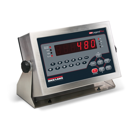
1.2 Overview The 480 is a single-channel digital weight indicator housed in a NEMA Type 4X/IP66-rated stainless steel enclosure. The indicator front panel consists of a large (.8 in/20 mm), six-digit, seven-segment LED display, with a seven-button keypad (480) or an 18-button full numeric keypad (480 Plus). Features •... -
Page 10: Front Panel Keypad
1.4 Front Panel Keypad See Section 1.7 for information about using the front panel keys in configuration mode. Numeric Keypad – Enter numeric values. See Section 1.7.1 on page 5. PRELIMINARY The up, down, enter, left and right arrows by the keys describe the functions assigned in the operating modes. -
Page 11: Led Annunciators
1.6 LED Annunciators The 480 display uses a set of eight LED annunciators to provide additional information about the value being displayed. Description Gross/Brutto LED Gross weight display mode (or Brutto in OIML mode) Net LED Net weight display mode Zero (Center of Zero) LED The Center of Zero LED indicates that the current gross weight reading is within +/- 0.25 display divisions of the acquired zero, or is within the center of zero band. -
Page 12: Numeric Keypad - Editing Procedure For Numeric Values (480 Plus Only)
Navigating Through Levels 1st Level 1st Level Parameter Parameter 2nd Level 2nd Level Parameter Parameter Default value Value Value Value When moving through values below the first menu level, press to return to the level above. Figure 1-3. Menu Navigation To select a parameter, press to scroll left or right until the desired menu group appears on the display, then press... -
Page 13: Indicator Operations
1.8 Indicator Operations Basic 480 operations are summarized below. 1.8.1 Menu MENU Press will be displayed. Menu Press , then to select the following parameters. • Audit Trail (See Section 1.8.10) • Display Tare (See Section 1.8.7) • Unit ID (See Section 1.8.11) •... -
Page 14: Preset Tare (Keyed Tare)
1.8.6 Preset Tare (Keyed Tare) TARE 1. With the scale empty and display showing zero weight, press is displayed with the focused 000000 digit flashing. 2. Edit the value using the following method; or with the 480 PLUS, use the keypad. See Section 1.7 on page 4. •... -
Page 15: Enter New Unit Id
1.8.11 Enter New Unit ID MENU 1. Press 2. Press AUDIT 3. Press until display reads UNIT ID 4. Press to view the current value. 5. Edit the value using the following method; or with the 480 PLUS, use the keypad. See Section 1.7 on page 4. •... -
Page 16: Display, Edit And Set Setpoint Value
1.8.14 Display, Edit and Set Setpoint Value See Section 8.0 on page 59 more information. MENU 1. Press 2. Press to AUDIT. 3. Press until display reads SETPNT 4. Press and navigate across to desired setpoint number (1-8). 5. Press and navigate across to select USER 6. -
Page 17: Installation
Immediately after unpacking, visually inspect the 480 to ensure all components are included and undamaged. The shipping carton should contain the indicator, this manual, and a parts kit. If any parts were damaged in shipment, notify Rice Lake Weighing Systems and the shipper immediately. See Section 2.8 on page 18 for parts kit contents. -
Page 18: Cable Grounding
2.3.1 Cable Grounding Except for the power cord, all cables routed through the cord grips should be grounded against the indicator enclosure. Do the following to ground shielded cables: • Use the ground clamp screws to install grounding clamps on the grounding bar. Do not tighten screws yet. There is a larger clamp available in the parts kit;... -
Page 19: Wiring
2.3.2 Wiring CPU Board A/D Board Option Card Bracket 20mA Comm 2 Connection Relay (DIO) Board Comm 1 & 2 Power Supply Connection Power Supply, CPU and A/D Board Analog Output Board Analog Output Connection Ethernet/USB Board Digital I/O Connection Analog Output and Relay Board Options Ethernet RJ45 Plug USB 5-Pin Plug... - Page 20 Standard Battery Option PN 131323 CPU Board PN 131318 A/D Board PN 131319 Battery Charger PN 131317 Power Supply PN 131316 J7 to display board Sense Jumpers J3 J4 Load Cell Connection Power Supply RS-232 Connection 20mA Connection Relay Board Ethernet/USB Board PN 131342 Analog Output...
-
Page 21: Battery Operation
2.4 Battery Operation The 480 can be equipped with an optional internal Lithium-Ion battery to provide up to: • 18 hours of continuous use (single load cell, 350 ohms, no options) • 15 hours of continuous use (four load cell, 350 ohms, no options) When operated on AC power, the internal battery is automatically charged by means of an internal battery charger circuit. -
Page 22: Option Card Installation
2.5 Option Card Installation Use the following instructions to install or replace the Analog Output Module (PN 131341), Relay Board (PN 131342) or Ethernet/USB option card (PN 164600). 1. Disconnect power to the indicator. 2. Remove backplate as described in Section 2.2 on page 10. 3. -
Page 23: Enclosure Reassembly
2.7 Enclosure Reassembly Once cabling is complete, position the backplate over the enclosure and reinstall the backplate screws. Use the torque pattern shown in Figure 2-5 to prevent distorting the backplate gasket. Torque screws to 10 in-lb (1 N-m). Step 1. Torque 1-4 in the order shown Step 2. -
Page 24: Seal The Indicator (Optional)
2.7.1 Seal the Indicator (Optional) For access to configuration parameters, the setup switch must be pressed. Prevents Service Access Insert a lead wire seal through three fillister screws. This prevents access to the electronics, electrical contacts and Legal for Trade configuration parameters. 11 - Screw, Pan Cross Head 8-32NC 1 - Screw, 1/4'' drilled... -
Page 25: Replacement Parts
2.8 Replacement Parts Representation only. Actual boards may look different. Figure 2-8. Replacement Parts 480 Legend Series... - Page 26 Item Item Part No. Description Part No. Description 164577 Knob & washer, M6 thread 131322 Battery bracket (Opt) 164579 Cover, A/D Sealing (optional) 131323 Battery, rechargeable (Opt) 164604 Ethernet cable with cord grip, 6 ft 131321 Backplate, back plane base 164602 USB Cable, Type A Female, 20 cm 14626...
-
Page 27: Configuration
3.0 Configuration There are two types of configuration parameters in the 480: Legal for Trade configuration and non-legal configuration (or operator parameters). Legal for Trade configuration requires pressing the setup switch (see Section 3.2). Non-legal configuration parameters do not require pressing the setup switch, but may be password protected. -
Page 29: User Menu Setup
3.1 User Menu Setup Press the key to access the menu parameters. Menu The menu key can be pushed while in the weigh mode. The configuration parameters can be accessed by pressing the setup switch while in the User Menu. See Section 3.2 for configuration setup. MENU CONFIG FORMAT... -
Page 30: Setpoint Menu
Parameter Choices Description PFRMAT GFMT View or configure the print format used for gross, net ticket, accumulator and setpoint NFMT print tickets. See Section 7.0 on page 57 for more information. ACCFMT See Section 3.1.5. SPFMT VERS FIRMW Displays the firmware and legally relevant firmware currently installed. MISC POWER Set miscellaneous parameters, see Section 3.1.7. - Page 31 Parameter Choices Description User submenus VALUE number Display and edit the setpoint target value. • For weight-based setpoints: specifies the target weight value, 0 – 999999. • For time-based setpoints (delay): specifies, in 0.1-second intervals, a time value in the range 0 –...
-
Page 32: Serial Menu
3.1.2 Serial Menu See Section 9.3 for information about the 480 serial data format. MENU CONFIG FORMAT CALIBR PROGRM DIG IN ALGOUT PASWRD USBMEM TEST ACCUM TIMDAT SETPNT SERIAL PFRMAT COM-1 TRIGER BAUD BITS SBITS TERMIN EOLDLY ECHO PRNMSG 9600 DEMAND 8NONE 1 STOP... - Page 33 Parameter Choices Description COM-1 TRIGER Specifies settings for COM-1. BAUD BITS SBITS TERMIN EOLDLY ECHO PRNMSG COM-2 TRIGER Specifies settings for COM-2. BAUD BITS SBITS TERMIN EOLDLY ECHO PRNMSG STRUR STREAM Specifies the operating mode of the indicator. See Section 9.4 on page 65. NONE Indicator operates normally, COM-2 will not stream, even if the TRIGER is set to a streaming parameter (STR1-5)
- Page 34 Parameter Choices Description SBITS 1 STOP Stop bits – Sets the number of stop bits to 1 or 2. 2 STOP TERMIN CR/LF Termination character – selects line termination character(s) for data sent. EOLDLY 000000 End-of-line delay – specifies, in 0.1 second intervals, the delay between transmitted lines of 0 –...
-
Page 35: Ethernet Menu
3.1.3 Ethernet Menu MENU CONFIG FORMAT CALIBR PROGRM DIG IN ALGOUT PASWRD USBMEM TEST SERIAL ETHNET DHCP IPADRS NETMSK DFTGWY SERVER CLIENT 00.00.00.00.00.00 0.0.0.0 0.0.0.0 0.0.0.0 TRIGER TIMOUT TERMIN SFMT PORT EOLDLY ECHO DEMAND CR/LF STR - 1 10001 COMAND 0 - 65535 STR - 2 1 - 65535... -
Page 36: Usb Menu
Parameter Choices Description SERVER/CLIENT Submenu TRIGER Selects the operation of the port. DEMAND Allows operation of EDP commands and will print. COMAND Allows operation of EDP commands only, does not print. STRLFT Stream legal for trade scale data – data is transmitted at the configured display update rate. -
Page 37: Print Format Menu
3.1.5 Print Format Menu See Section 7.0 for information about custom print formatting. MENU CONFIG FORMAT CALIBR PROGRM DIG IN ALGOUT PASWRD USBMEM TEST ACCUM TIMDAT SETPNT SERIAL PFRMAT GFMT NFMT ACCFMT SPFMT Press to insert a space before the active character Display first 6 Scroll left in format string Scroll right in format string... -
Page 38: Misc Menu
3.1.7 MISC Menu MENU CONFIG FORMAT CALIBR PROGRM DIG IN ALGOUT PASWRD USBMEM TEST MISC POWER BKLGHT AUTO BAT LEVEL MANUAL AUTO 10 SEC 30 SEC 1 MIN 5 MIN 10 MIN Figure 3-8. Misc. Menu Parameter Choices Description POWER AUTO The power up functionality depends on whether the battery option is installed: •... -
Page 39: Configuration Using The Front Panel (Legal For Trade)
3.2 Configuration Using the Front Panel (Legal for Trade) The 480 indicator can be configured using a series of menus accessed through the indicator front panel when the indicator is in configuration mode. When the indicator is placed in configuration mode, is shown on the display. -
Page 40: Configuration Menu Structures And Parameter Descriptions
3.2.1 Configuration Menu Structures and Parameter Descriptions CONFIG FORMAT CALIBR PROGRM DIG IN ALGOUT PASWRD USBMEM TEST MENU GRADS ZTRKBN ZRANGE INIZR MOTBAN OVRLOA DSPRAT SMPRAT 010000 0 dd 0.1 d FS-2% 0.10 SEC 5 HZ FS-1D 0.25 SEC 10 HZ 0.50 SEC FS-9D 20 HZ... -
Page 41: Adaptive Filter And Rolling Filter Sub-Menu Parameters
Parameter Choices Description OVRLOA FS+2% Overload – determines the point at which the display blanks and an out-of-range error FS+1D message is displayed. Maximum legal value varies depending on local regulations. FS+9D DSPRAT 0.1SEC Display rate – sets the update rate for displayed values. Values are in seconds (SEC). 0.25 SEC 0.5 SEC 0.75 SEC... - Page 42 Description Parameter Choices ADPFIL Sub-menu AFSENS LIGHT Digital filter cutout sensitivity – the light setting responds quickly to small weight changes and MEDIUM is less stable. The heavy setting responds slowly to small weight changes and is more stable. HEAVY Use the heavy setting in an unstable environment.
-
Page 43: Format Menu
3.2.3 Format Menu CONFIG FORMAT CALIBR PROGRM DIG IN ALGOUT PASWRD USBMEM TEST MENU SECNDR PRIMAR DECPNT DSPDIV UNITS DECPNT DSPDIV UNITS 88888.8 888888 888888 8.88888 88.8888 8.88888 888.888 88.8888 8888.88 888.888 88888.8 8888.88 Figure 3-11. Format Menu Parameter Choices Description PRIMAR DECPNT... -
Page 44: Calibration Menu
3.2.4 Calibration Menu See Section 4.0 on page 46 for Calibration procedures. CONFIG FORMAT CALIBR PROGRM DIG IN ALGOUT PASWRD USBMEM TEST MENU WZERO WVAL REZERO WSPAN EDIT 000000 EDIT ZERO Display and edit Display and edit Display and edit Press Enter to test weight value zero calibration... -
Page 45: Program Menu
3.2.5 Program Menu CONFIG FORMAT CALIBR PROGRM DIG IN ALGOUT PASWRD USBMEM TEST MENU PWRUPM REGULA CONSNU CONSTU ACCUM RTZGRD DATE 000000 000000 NTEP DATFMT DATSEP DELAY OIML 0-999999 0-999999 MMDDYY SLASH CANADA DDMMYY DASH NONE SEMI YYMMDD YYDDMM TIME SLEEP STDBY WGTHRH... - Page 46 Parameter Choices Description PWRUPM Power up mode – when set to GO, the indicator goes into operation immediately after a brief DELAY power up display test. When set to DELAY, the indicator performs a power up display test and then enters a 30 second warm-up period.
- Page 47 Parameter Choices Description WGTHRH 0 – FS Controls the Weight Threshold of the Sleep Mode. (in primary If the weight is above WGTHRH, the indicator will not go into sleep mode. units ) If the weight is below WGTHRH, it will go into sleep mode if the weight remains stable and no buttons are pressed, for the time set in the Sleep mode parameter.
-
Page 48: Digital Input Menu
3.2.6 Digital Input Menu CONFIG FORMAT CALIBR PROGRM DIG IN ALGOUT PASWRD USBMEM TEST MENU DIGIN1-4 KBDLOC BATPUS ZERO HOLD BATRUN TARE CLRTAR NT-GRS ACCUM GROSS UNITS CLRACC DPSTAR BATSTR PRINT BATSTP CLRCN BATRES Figure 3-14. Digital Input Menu Parameter Choices Description DIGIN1... -
Page 49: Analog Output Menu
3.2.7 Analog Output Menu If the analog output option is installed, configure all other indicator functions and calibrate the indicator (see Section 4.0 on page 46) before configuring the analog output. See Section 9.12 on page 70 for analog output calibration procedures. -
Page 50: Password Menu
3.2.8 Password Menu The PASSW menu is used to edit or set passwords. CONFIG FORMAT CALIBR PROGRM DIG IN ALGOUT PASWRD USBMEM TEST MENU CNFG USER 000000 000000 Figure 3-16. Password Menu Parameter Choices Description CNFG Edit configuration password. 0 = no password 0 –... -
Page 51: Test Menu
3.2.10 Test Menu Access to this menu requires the configuration password if it has been enabled. CONFIG FORMAT CALIBR PROGRM DIG IN ALGOUT PASWRD USBMEM TEST MENU ADTEST NWGMNT WGMNST DIGIN DIGOUT ALGOUT DEFLT Raw A/D TOTAL 999999 Counts OVERCAP VIEW 100% Figure 3-18. -
Page 52: Revolution Configuration
3.3 Revolution Configuration ® The Revolution configuration utility provides another method for configuring the 480 indicator. Revolution runs on a computer to set configuration parameters for the indicator. When Revolution configuration is complete, configuration data is downloaded to the indicator. Revolution supports both uploading and downloading of indicator configuration data. -
Page 53: Calibration
4.0 Calibration ® The 480 can be calibrated using the front panel or the Revolution configuration utility. Each method consists of the following steps: • Zero calibration • Entering the test weight value • Span calibration • Optional rezero calibration for test weights using hooks or chains. The following sections describe the calibration procedure for each of the calibration methods. -
Page 54: Edp Command Calibration
4.2 EDP Command Calibration To calibrate the indicator using EDP commands, the indicator COM 1 port must be connected to a terminal or computer. See Section 6.0 on page 51 for more information about using EDP commands. Once the indicator is connected to the sending device, use the following steps: 1. -
Page 55: More About Calibration
4.4 More About Calibration The following provides additional information about and how to manually tweak a calibration up or down. WVAL WVAL When a WVAL number is entered that uses a decimal point, the value will be rounded when displayed. Example: A precision value such as 2455.23 is entered by the operator, but when the operator returns to the WVAL display, the number is rounded to 2455. -
Page 56: Revolution
Revolution ® The Revolution utility provides a suite of functions used to support configuration, calibration, customization and backup of the 480 software. Calibration values and scale configuration can both be saved and restored to the 480 using Revolution. Hardware and Software Requirements •... -
Page 57: Reflash Indicator
To download configuration data, connect the PC to the selected port as described in Section 5.2.1. Place the indicator in configuration mode and use the PC communications software to send the saved configuration data to the indicator. When transfer is complete, calibrate the indicator as described in Section 4.0. Reflash Indicator The 480/482 flash loader program must be downloaded on the PC being used. -
Page 58: Edp Commands
EDP Commands EDP commands are case sensitive. Commands must be entered in upper case. The 480 indicator can be controlled by a computer or remote keyboard connected to one of the indicator’s communication ports. Control is provided by a set of EDP commands that can simulate front panel key press functions, display and change setup parameters, and perform reporting functions. -
Page 59: Reporting Commands
6.1.2 Reporting Commands Reporting commands (see Table 6-2) send specific information to the selected port. These commands can be used in both setup mode and weigh mode. Command Function DUMPALL Lists all parameter values. DUMPAUDIT Lists audit data information. Writes current displayed weight with units identifier. See Section 9.2 on page 61 for more information. Writes current weight and annunciator status. - Page 60 Command Description Values SC.PRI.DECPNT Primary units decimal position 8.88888, 88.8888, 888.888, 8888.88, 88888.8, 888888 SC.PRI.DSPDIV Primary units display divisions 1D, 2D, 5D, 10D, 20D , 50D SC.PRI.UNITS Primary units LB, KG, OZ, TN, T, G SC.SEC.DECPNT Secondary units decimal position 8.88888, 88.8888, 888.888, 8888.88, 88888.8, 888888 SC.SEC.DSPDIV Secondary units display divisions...
- Page 61 Command Description Values ALG.SOURCE Analog output source GROSS, NET ALG.OFFSET Zero offset 0%, 20% ALG.ERRACT Error action FULLSC, HOLD, ZEROSC ALG.MIN Minimum value tracked 0 – 999999 ALG.MAX Maximum value tracked 0 – 999999 ALG.MINNEG Minimum negative NO, YES ALG.MAXNEG Maximum negative NO, YES ALG.TWZERO...
- Page 62 Ethernet Functionality The Ethernet port works in COMMAND mode meaning that it is possible to send any EDP command to the indicator and receive a response from the indicator accordingly. It is not possible to print from the port. Command Description Values ETH.DHCP...
-
Page 63: Normal Mode Commands
6.1.6 Normal Mode Commands The serial transmit weight data commands (see Table 6-15) transmit data to the selected port on demand. The SX and EX commands are valid only in weigh mode; all other commands are valid in either setup or weigh mode. Command Description Response Format... -
Page 64: Print Formatting
Print Formatting The 480 provides multiple print formats, GFMT, NFMT, ACCFMT and SPFMT, that determine the format of the printed output when the key is pressed. If a tare has been entered or acquired, NFMT is used; otherwise, Print GFMT is used. Each print format can be customized to include up to 300 characters of information, such as company name and address, on printed tickets. -
Page 65: Customizing Print Formats
The default 480 print formats are shown in Table 7-2: Format Default Format String When Used GFMT GROSS<G><NL2><TD><NL> Weigh mode – no tare in system NFMT GROSS<G><NL>TARE<SP><T><NL>NET<SP2><N> Weigh mode – tare in system <NL2><TD><NL> ACCFMT ACCUM <A><NL><DA><SP><TI><NL> Accumulator demand print format string SPFMT <SCV><SP><SPM><NL>... -
Page 66: Setpoints
Setpoints The 480 indicator provides eight configurable setpoints for control of both indicator and external equipment functions. Setpoints can be configured to perform actions or functions based on specified parameter conditions. Parameters associated with various setpoint kinds can, for example, be configured to perform functions (print, tare, accumulate), to change the state of a digital output controlling indicator or external equipment functions, or to make conditional decisions. -
Page 67: Appendix
A/D converter requires recalibration. Call Rice Lake Weighing Systems Service. ERROR Internal program error Check configuration. Call Rice Lake Weighing Systems Service if unable to clear error by cycling power or if error recurs. OVERFL Overflow error Weight value too large to be displayed. -
Page 68: Using The Xe Edp Command
9.1.2 Using the XE EDP Command The XE EDP command can be used to remotely query the 480 for the error conditions shown on the front panel. The XE command returns two five digit numbers in the format: xxxxx yyyyy where contains a decimal representation of any existing error conditions as described in Table 9-2. -
Page 69: Continuous Data (Stream) Output Formats
Leading zeroes transmitted as spaces. Figure 9-1. STR-1 Rice Lake Stream Data Format Set format 5 if receiving device cannot read a status bit Z. 480 Legend Series... - Page 70 <STX> <SWA> <SWB> <SWC> <wwwwww> <tttttt> <CR> Status Word B <CR> entered at end STX (02h) of string. Status Word A Status Word C Six digits, right justified, dummy zeros, decimal Tare Weight: Six digits, right justified, point with no leading zeroes except for immediately dummy zeros, decimal point with no preceding the decimal point.
- Page 71 <CR> <POL> <wwwwww> <S> <SP> <UNIT> <SP> <G/N> <SP> <SP> <ETX> Carriage Space Space g for Gross Hex value of <03> Return Character Character n for Net is entered in string Status: Polarity: Space character lb = pound <space> = valid or invalid <+>...
-
Page 72: Local/Remote Operation
Local/Remote Operation For systems that require two locations, local/remote support provides function equivalent to that of a Legal for Trade remote display with keypad. Scale data from the local indicator is also displayed at the remote unit, and keypad input from the remote allows transactions to be initiated from either the local or remote unit. To configure for local/remote operation, set STREAM to local or remote. -
Page 73: Internal Battery Option
Example: If the standby parameter set to 1 second, the weight threshold to 100, and the display division threshold is set to 10d, once in sleep mode, the indicator will wake up every second for about half a second to check to see if a key is being pressed, the weight threshold is over 100 (WGTHRH), or the weight has change more than 10d (DDTHRH) since the last time it checked. -
Page 74: Ethernet Option
Save the Configuration 1. Attach a flash drive to the USB port. 2. Enter the configuration menu and navigate go to . See Section 3.2 on page 32. USBMEM 3. Press , then press to select . See Section 3.2.9 on page 43. SAVE 4. -
Page 75: Conversion Factors For Secondary Units
9.10 Conversion Factors for Secondary Units The 480 has the capability to mathematically convert a weight into many different types of units and instantly display those results with a press of the key. Unit Secondary units can be specified on the Format menu using the parameter. -
Page 76: Rolling Averaging Filter
9.11.3 Rolling Averaging Filter The rolling averaging filter uses mathematical averaging with three stages. These configurable stages control the effect of a single A/D reading on the displayed weight. When an A/D reading is encountered that is outside a predetermined band, the rolling averaging filter is overridden and the display jumps directly to the new value. Filter Stages (RFSTG1-3) The filter stages can each be set to a value of 1 to 64. -
Page 77: Analog Output Calibration
9.12 Analog Output Calibration The following calibration procedure requires a multimeter to measure voltage or current output from the analog output module. See Figure 3-15 for analog output menu structure. The analog output must be calibrated after the indicator itself has been configured (see Section 3.0) and calibrated (see Section 4.0). -
Page 78: Regulatory Mode Functions
9.14 Regulatory Mode Functions Regulatory Weight On Tare In Front Panel Front Panel Parameter Scale System Key Tare Key Zero “000000” Zero Zero Clear tare Zero No action Zero NTEP Negative Clear tare Zero Tare Zero Positive Tare Zero “000000” Zero Zero Clear tare... -
Page 79: Ascii Character Chart
9.15 ASCII Character Chart Use the decimal values for ASCII characters listed in Tables 9-6 and 9-7 when specifying print format strings on the 480 PFORMT menu. The actual character printed depends on the character mapping used by the output device. The 480 can send or receive any ASCII character value (decimal 0–255), but the indicator display is limited to numbers, upper-case, unaccented letters and a few special characters. - Page 80 ASCII ASCII ASCII ASCII Ç á ü í ß é ó â ú ä ñ à Ñ å ª μ ç º ê ¿ ë è ¬ ï î ...
-
Page 81: Front Panel Display Characters
9.16 Front Panel Display Characters Figure 9-6 shows the seven-segment LED character set used to display alphanumeric characters on the 480 front panel. < & > Figure 9-6. Display Characters 480 Legend Series... -
Page 82: Specifications
9.17 Specifications Model Numbers Digital I/O (Optional) United States 480-2A/480Plus-2A (NEMA Type 5-15) Type Fully isolated International 480-2A/480Plus-2A (CEE 7/7) Digital Inputs 2 or 4 inputs, Opto isolated, 5 to 24 VDC input, active high Power – AC Digital Outputs... - Page 83 480 Legend Series...
- Page 85 Specifications subject to change without notice. Rice Lake Weighing Systems is an ISO 9001 registered company. 230 W. Coleman St. • Rice Lake, WI 54868 • USA U.S. 800-472-6703 • Canada/Mexico 800-321-6703 • International 715-234-9171 • Europe +31 (0)26 472 1319 www.ricelake.com www.ricelake.mx www.ricelake.eu www.ricelake.co.in m.ricelake.com...
Need help?
Do you have a question about the 480Plus-2A and is the answer not in the manual?
Questions and answers