Mitel 3300 ICP Hardware User's Manual
Integrated communications platform
Hide thumbs
Also See for 3300 ICP:
- Technician's handbook (188 pages) ,
- Hardware technical reference manual (142 pages) ,
- General information manual (119 pages)
Table of Contents
Advertisement
Quick Links
Advertisement
Table of Contents
Troubleshooting

Related Manuals for Mitel 3300 ICP


Summary of Contents for Mitel 3300 ICP
- Page 1 HARDWARE USER GUIDE...
-
Page 3: Table Of Contents
Mitel Networks 3300 Controller Dimensions ........55... - Page 4 3300 Universal NSU DIP Switch Settings ........58 Mitel Networks™ 3300 R2 NSU Components ....... . 59 3300 R2 NSU Protocols .
- Page 5 Table of Contents Chapter 3 - Installing Installing ..............111 Required Components .
- Page 6 Install 3300 ICP as a Stand-alone IP Gateway ....... . .
- Page 7 Software Upgrade Procedure (3.2 to 3.3) ........195 Upgrade SX-2000 LIGHT to 3300 ICP Software ......202 Upgrade SX-2000 MICRO LIGHT to 3300 ICP Software .
- Page 8 3300 ICP Hardware User Guide Troubleshooting ............239 Peripheral Unit .
-
Page 9: Before You Begin
Chapter 1 Before You Begin... - Page 10 3300 ICP Hardware User Guide Release 3.3...
-
Page 11: Printing The Hardware User Guide
Optimized system performance: 300 MHz E2T and RTC • Symbol wireless telephones • 3300 ICP as a Stand-alone Wireless Gateway • 3300 ICP as a Stand-alone Voice Mail • Range programming to simplify the addition, change, or deletion of repetitive or incremental values •... -
Page 12: Disclaimer
Mitel Networks Corporation (MITEL®). The information is subject to change without notice and should not be construed in any way as a commitment by Mitel or any of its affiliates or subsidiaries. Mitel and its affiliates and subsidiaries assume no responsibility for any errors or omissions in this document. -
Page 13: Safety Instructions
Before You Begin Safety Instructions You can access a printable version of the Safety Instructions from our edocs web site. Note: You must have Adobe Acrobat Reader to view and print the Safety Instructions. ® If you need a copy of Adobe Acrobat Reader, it is available for download at ®... - Page 14 3300 ICP Hardware User Guide Release 3.3...
-
Page 15: Chapter 2 - Specifications
Chapter 2 Specifications... - Page 16 3300 ICP Hardware User Guide Release 3.3...
-
Page 17: Technical Information
Input Signaling: The system is capable of accepting and repeating the standard DTMF tones as specified in EIA/TIA 464-C. Output Signaling: The Mitel Networks 3300 ICP meets the output signaling requirements as specified in EIA/TIA 464-C. DTMF Output Signaling as specified by EIA/TIA 464-C... - Page 18 3300 ICP Hardware User Guide dial the digit ‘1’ on an ordinary rotary telephone. • Station switchhook flashes of less than the maximum programmed switchhook flash time will not be repeated towards the central office. • An open Tip lead condition of 500 ms (optional 100 ms) or more duration on a CO trunk will release the system connection.
-
Page 19: Transmission Characteristics
• ETSI ES 202 020 'Harmonized Pan-European/North American loss and level plan for voice gateways to IP based networks'. Mitel Networks digital telephones meet the requirements of: • ANSI/TIA/EIA-810-A 'Transmission Requirements for Narrowband Voice over IP and Voice over PCM Digital Wireline Telephones'. - Page 20 (e.g. In North America, OPS to WAN is a -3dB gain and WAN to OPS is a 9dB loss). Note: Mitel Networks digital telephones meet the following ITU-T recommended loudness rating: - Send Loudness Rating (SLR) 8 dB - Receive Loudness Rating (RLR) 2 dB.
- Page 21 Specifications Australia Loss Plan Matrix iONS iOPS iACO iACOs ACOs ↑ ↑ ↑ ↑ ↑ ↑ ↑ ↑ ↑ ↑ ↑ ↑ → iONS → → iOPS → → → → → iACO → iACOs → → ACOs → Brazil Loss Plan Matrix iONS iOPS...
- Page 22 3300 ICP Hardware User Guide France Loss Plan Matrix iONS iOPS iACO iACOs ACOs ↑ ↑ ↑ ↑ ↑ ↑ ↑ ↑ ↑ ↑ ↑ ↑ → iONS → → iOPS → → → → → iACO → iACOs →...
- Page 23 Specifications Germany Loss Plan Matrix iONS iOPS iACO iACOs ACOs ↑ ↑ ↑ ↑ ↑ ↑ ↑ ↑ ↑ ↑ ↑ ↑ iONS → → iOPS → → → → → iACO → iACOs → → ACOs → → Italy Loss Plan Matrix iONS iOPS...
- Page 24 3300 ICP Hardware User Guide Latin America Loss Plan Matrix iONS iOPS iACO iACOs ACOs ↑ ↑ ↑ ↑ ↑ ↑ ↑ ↑ ↑ ↑ ↑ ↑ iONS → → iOPS → → → → → iACO → iACOs →...
- Page 25 Specifications New Zealand Loss Plan Matrix iONS iOPS iACO iACOs ACOs ↑ ↑ ↑ ↑ ↑ ↑ ↑ ↑ ↑ ↑ ↑ ↑ iONS → → iOPS → → → → → iACO → iACOs → → ACOs → → North America Loss Plan Matrix iONS...
- Page 26 3300 ICP Hardware User Guide Portugal Loss Plan Matrix iONS iOPS iACO iACOs ACOs ↑ ↑ ↑ ↑ ↑ ↑ ↑ ↑ ↑ ↑ ↑ ↑ → iONS → → iOPS → → → → → iACO → iACOs →...
-
Page 27: Tone Plans
Specifications United Kingdom Loss Plan Matrix iONS iOPS iACO iACOs ACOs ↑ ↑ ↑ ↑ ↑ ↑ ↑ ↑ ↑ ↑ ↑ ↑ iONS → → iOPS → → → → → iACO → iACOs → → ACOs → → Tone Plans Tone plans permit the station user to distinguish different stages of call progress and different types of calls. - Page 28 3300 ICP Hardware User Guide Tone Output Level iONS iOPS iACO iACOs ACOs ARS 2nd Dial Busy Dial Camp-on Conference Confirmation Feature Active Dial Interrupted Dial Message Notification Modem Answer Override Paging Reorder Ringback Special Busy Special Ringback Transfer Dial Voice Mail Note: DTMF tones are supported.
- Page 29 Specifications Tone Output Level iONS iOPS iACO iACOs ACOs ARS 2nd Dial Busy Dial Camp-on Conference Confirmation Feature Active Dial Interrupted Dial Message Notification -23, -23, -20, -20, -20, -20, -20, -20, -20, -17, -17, -14, -14, -14, -14, -14, -14, -14, Modem Answer...
- Page 30 3300 ICP Hardware User Guide France Tone Plan Frequency Tone Cadence (s) (Hz) ARS 2nd Dial Continuous Busy 0.5 on, 0.5 off, repeat Camp-on 0.2 on, off Conference 0.6 on, off Confirmation Continuous Dial Tone Continuous Feature Active Dial 0.75 on, 0.75 off, then continuous Interrupted Dial 0.75 on, 0.75 off, then continuous...
- Page 31 Specifications Tone Output Level iONS iOPS iACO iACOs ACOs Special Busy Special Ringback Transfer Dial Voice Mail Page 2 of 2 Note: DTMF tones are supported. Note: Digital (DGS) and IP (WAN) tones are conveyed as Real-Time Transfer Protocol (RTP) packets. Note: "---"...
- Page 32 3300 ICP Hardware User Guide Tone Output Level iONS iOPS iACO iACOs ACOs ARS 2nd Dial Busy Dial Camp-on Conference Confirmation External Camp-on Feature Active Dial Interrupted Dial Message Notification Modem Answer Override Paging Reorder Ringback Special Busy Special Ringback...
- Page 33 Specifications Tone Output Levels iONS iOPS iACO iACOs ACOs ARS 2nd Dial Busy Dial Camp-on Conference Confirmation Feature Active Dial Interrupted Dial Message Notification Modem Answer Override Paging Reorder Ringback Special Busy Special Ringback Transfer Dial Voice Mail Note: DTMF tones are supported. Note: Digital (DGS) and IP (WAN) tones are conveyed as Real-Time Transfer Protocol (RTP) packets.
- Page 34 3300 ICP Hardware User Guide Latin America Tone Plan Frequency Tone Cadence (s) (Hz) ARS 2nd Dial Continuous Busy 480/620 0.5 on, 0.5 off, repeat Camp-on 0.1 on, 0.05 off, repeat x 2 Conference 1 on, off Confirmation 350/440 Continuous...
- Page 35 Specifications Tone Output Level iONS iOPS iACO iACOs ACOs Special Ringback Transfer Dial Voice Mail Page 2 of 2 Note: DTMF tones are supported. Note: Digital (DGS) and IP (WAN) tones are conveyed as Real-Time Transfer Protocol (RTP) packets. Note: "---" indicates that this interface is not supported in this country. Netherlands Tone Plan Tone...
- Page 36 3300 ICP Hardware User Guide Tone Output Levels iONS iOPS iACO iACOs ACOs ARS 2nd Dial Busy Dial Camp-on Conference Confirmation Feature Active Dial Interrupted Dial Message Notification Modem Answer Override Paging Reorder Ringback Special Busy Special Ringback Transfer Dial Voice Mail Note: DTMF tones are supported.
- Page 37 Specifications Tone Plan (continued) Frequency Tone Cadence (s) (Hz) Ringback 400/450 1 on, 2 off, repeat Special Busy 0.35 on, 0.35 off, repeat Special Ringback 400/450 0.4 on, 0.2 off, 0.4 on, 2.0 off, repeat forever Transfer Dial (0.1 on, 0.1 off) x 3, then continuous Voice Mail 0.6 on, off Page 2 of 2...
- Page 38 3300 ICP Hardware User Guide North America Tone Plan Frequency Tone Cadence (s) (Hz) ARS 2nd Dial 350/440 Continuous Busy 480/620 0.5 on, 0.5 off, repeat Camp-on 0.1 on, 0.05 off, repeat x 2 Conference 1 on, off Confirmation 350/440...
- Page 39 Specifications Portugal Tone Plan Tone Frequency (Hz) Cadence (s) ARS 2nd Dial Continuous Busy 0.2 on, 0.2 off, repeat Camp-on 0.2 on, .01 off, 0.2 on, 0.1 off Conference 0.2 on, off Confirmation 0.1 on, 0.1 off, 0.1 on, 0.7 off, repeat Dial 350/425 Continuous...
- Page 40 3300 ICP Hardware User Guide Spain Tone Plan Frequency Tone Cadence (s) (Hz) ARS 2nd Dial Continuous Busy 0.2 on, 0.2 off, repeat Camp-on 0.6 on, 0.2 off, 0.6 on, off Conference 1400 0.4 on, off Confirmation Continuous Dial Continuous Feature Active Dial (0.1 on, 0.1 off) x 8, then continuous...
- Page 41 Specifications Tone Output Levels iONS iOPS iACO iACOs ACOs Transfer Dial Voice Mail Page 2 of 2 Note: DTMF tones are supported. Note: Digital (DGS) and IP (WAN) tones are conveyed as Real-Time Transfer Protocol (RTP) packets. Note: "---" indicates that this interface is not supported in this country. United Kingdom Tone Plan Frequency...
- Page 42 3300 ICP Hardware User Guide Tone Output Level iACO iONS iOPS iACO ACOs ARS 2nd Dial Busy Dial Camp-on Conference Confirmation Feature Active Dial Interrupted Dial Message Notification Modem Answer Override Paging Reorder Ringback Special Busy Special Ringback Page 1 of 2...
-
Page 43: E2T Compression
64 kbps to approximately 8 kbps plus packet overhead. Voice compression on the 3300 ICP can be divided into two types: IP phone-to IP phone and IP phone to TDM/analog devices. - Page 44 3300 ICP Hardware User Guide When controllers are networked together the compression becomes more complex. The following examples are assuming that the IP devices are in different compression zones. The WAN link is assumed to be G.729 compressed. The LAN link is assumed to be in the same compression zone and running G.711.
- Page 45 Specifications The following examples assume that compression is not being used within the LAN, each node is in a separate compression zone and Node A is the host of each conference call. For example: A three-party conference is established between a TDM device and an IP device on Node A across a LAN, and an IP device on Node B across a WAN.
-
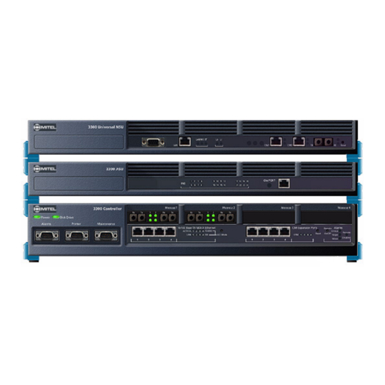
Page 46: 3300 Controller
3300 ICP Hardware User Guide 3300 Controller 100 Controller Mitel Networks™ 3300 - 100 Controller Components Front Panel • Remote Alarm port (DB-9 connector) • Two RS-232 ports (DB-9 connectors) (Printer and Maintenance) • Dual fiber interface module (FIM) ports to support the NSUs (Network Services Units) or the Peripheral unit. -
Page 47: Configurations
Power fail protected real-time clock • Digital Signal Processor (DSP) (provides telecom functions) • Two cooling fans. Configurations There are several configuration options for the 3300 ICP (100 Controller): • 100 User System without Compression • 100 User System with 32 Compression Channels •... -
Page 48: 100 User System Without Compression
3300 ICP Hardware User Guide 100 User System without Compression This system uses: • One embedded 300 MHz RTC/E2T processor • One embedded 64 Channel Echo Canceller • One dual FIM • One DSP Module (21161) for telecom support This provides: •... -
Page 49: 100 User System With 32 Compression Channels
Specifications 100 User System with 32 Compression Channels This system uses: • One embedded 300 MHz RTC/E2T processor • One embedded 64 Channel Echo Canceller • One dual FIM • One DSP Module (21161) for telecom support • One DSP Module (21161) for 32 channels of compression This provides: •... -
Page 50: 100 User System With 30 Voice Mail Ports
3300 ICP Hardware User Guide 100 User System with 30 Voice Mail Ports This system uses: • One embedded 300 MHz RTC/E2T processor • One embedded 64 Channel Echo Canceller • One dual FIM • One DSP Module (21161) for telecom support •... -
Page 51: 100 User System With 32 Compression Channels And 30 Voice Mail Ports
Specifications 100 User System with 32 Compression Channels and 30 Voice Mail Ports This system uses: • One embedded 300 MHz RTC/E2T processor • One embedded 64 Channel Echo Canceller • One dual FIM • One DSP Module (21161) for telecom support •... -
Page 52: 3300 Controller
3300 ICP Hardware User Guide 3300 Controller 250 and 700 Controller Mitel Networks™ 3300 - 250 and 700 Controller Components Front Panel • Remote Alarm port (DB-9 connector) • Two RS-232 ports (DB-9 connectors) (Printer and Maintenance) • Dual FIM ports to support the NSUs (Network Services Units) or a Peripheral Unit •... -
Page 53: Configurations
Digital Signal Processor (DSP) (provides for tone and conference functions) • Two cooling fans. Configurations There are several configuration options for the 3300 ICP (250 and 700 Controller): • 250 user system without compression • 250 user system with 30 voice mail ports •... - Page 54 3300 ICP Hardware User Guide 250 User System without Compression This system uses: • One 300 MHz RTC • One 300 MHz E2T • One 64 Channel Echo Canceller • One Dual FIM • One DSP Module (21061/21161) for telecom support This provides: •...
- Page 55 Specifications 250 User System with 30 Voice Mail Ports This system uses: • One 300 MHz RTC • One 300 MHz E2T • One 64 Channel Echo Canceller • One Dual FIM • One DSP Module (21061/21161) for telecom support •...
- Page 56 3300 ICP Hardware User Guide 250 User System with 32 Compression Channels This system uses: • One 300 MHz RTC • One 300 MHz E2T • One 64 Channel Echo Canceller • One Dual FIM • One DSP Module (21061/21161) for telecom support •...
- Page 57 Specifications 250 User System with 32 Compression Channels and 30 Voice Mail Ports This system uses: • One 300 MHz RTC • One 300 MHz E2T • One 64 Channel Echo Canceller • One Dual FIM • One DSP Module (21061/21161) for telecom support •...
- Page 58 3300 ICP Hardware User Guide 250 User System with 64 Compression Channels This system uses: • One 300 MHz RTC • One 300 MHz E2T • One 64 Channel Echo Canceller • One Dual FIM • One DSP Module (21061/21161) for telecom support •...
- Page 59 Specifications 250 User System with 64 Compression Channels and 30 Voice Mail Ports This system uses: • One 300 MHz RTC • One 300 MHz E2T • One 64 Channel Echo Canceller • One Dual FIM • One DSP Module (21061/21161) for telecom support •...
- Page 60 3300 ICP Hardware User Guide 700 User System without Compression This system uses: • One 300 MHz RTC • One 300 MHz E2T • One 128 Channel Echo Canceller • Two Dual FIMs • Two DSP Modules (21061/21161) for telecom support This provides: •...
- Page 61 Specifications 700 User System with 32 Compression Channels This system uses: • One 300 MHz RTC • One 300 MHz E2T • One 128 Channel Echo Canceller • Two Dual FIMs • Two DSP Modules (21061/21161) for telecom support • One DSP Module (21161) for 32 channels of compression This provides: •...
- Page 62 3300 ICP Hardware User Guide 700 User System with 64 Compression Channels This system uses: • One 300 MHz RTC • One 300 MHz E2T • One 128 Channel Echo Canceller • Two Dual FIMs • Two DSP Modules (21061/21161) for telecom support •...
-
Page 63: Mitel Networks 3300 Controller Dimensions
Specifications Mitel Networks 3300 Controller Dimensions Physical Dimensions Height 2.625 in. (6.66 cm) (1.5 U) Width 17.75 in. (45.1 cm) (19" rack mountable) Depth 15.5 in. (39.4 cm) Weight 15.8 lb (7.17 kg) 3300 Controller Environment Storage Environment Condition Specification Temperature -40º... -
Page 64: 3300 Controller Pcb Interfaces
3300 ICP Hardware User Guide Output Power Output Voltage Max Current +3.3 +/- 1.5% 30.0A +5.0V +/- 1% 8.0A (Total power of 3.3V and 5.0V not to exceed 100W) +12.0V +/- 7% 3.0A (Hard Disk Drive) 3300 Controller PCB Interfaces... -
Page 65: 3300 Network Services Units
Specifications 3300 Network Services Units Mitel Networks™ 3300 Universal NSU Components Front panel • RS-232 serial port (DB9 connector to a PC) for maintenance purposes such as field installation, database upgrade, access to logs, and modem connection for remote access •... -
Page 66: 3300 Universal Nsu Protocols
3300 ICP Hardware User Guide 3300 Universal NSU Protocols The 3300 Universal NSU provides T1 or E1 connectivity and supports up to two links per unit. The protocols supported by the interfaces are: • T1 - PRI, Q.Sig, DPNSS, T1/D4 •... -
Page 67: Mitel Networks™ 3300 R2 Nsu Components
Specifications Mitel Networks™ 3300 R2 NSU Components Front panel • RS-232 serial port (DB9 connector to a PC) for maintenance purposes such as field installation, database upgrade, access to logs, and modem connection for remote access • Ethernet port (RJ-45 connector) for future use •... -
Page 68: 3300 R2 Nsu Dip Switch Settings
3300 ICP Hardware User Guide 3300 R2 NSU DIP Switch Settings MF-R2 Port DIP Switch Settings DIP Switch Default Setting Notes Tx Ground Tx shield ground when down Rx Ground Rx shield ground when down Impedance selector #1 120 ohm... -
Page 69: 3300 Bri Nsu Protocols
UK version. The 3300 BRI NSU protocols are • Euro-ISDN 2B+D, Basic Rate Interface • North American National ISDN-1 • North American National ISDN-2. Mitel Networks 3300 NSU Dimensions Physical Dimensions Height 1.75 in. (4.454 cm) (1 U) Width 17.75 in. (45.1 cm) (19" rack mountable) Depth 15.5 in. -
Page 70: 3300 Nsu Power
3300 ICP Hardware User Guide Operational Environment Condition Specification Temperature 41º to 122ºF (5º to 50ºC) Humidity 34-95% Relative Humidity, non-condensing Maximum Heat Dissipation - 170 BTUs per hour fully loaded (see Note) Conversion factors: 1 watt is equal to 3.412 BTUs per hour, 1 ton of refrigeration is equal to 12,000 BTUs per hour or 3.516 Kilowatts, and 3/4 Kilowatt-hour is equal to 1 ton of refrigeration. - Page 71 Specifications RS-232 Maintenance Connector Allocation Signal Name RJ-45 Connector Pin DTR (data terminal ready) DCD (data carrier detector) RXD (receive data) TXD (transmit data) DTR (data terminal ready) Not used RTS (ready to send) CTS (clear to send) Not used BRI Connector Allocation Release 3.3...
-
Page 72: 3300 Analog Services Units
3300 ICP Hardware User Guide 3300 Analog Services Units Mitel Networks™ 3300 Universal ASU Components Front Panel • 16 ONS LEDs showing circuit status • 4 LS trunk LEDs showing circuit status • 1 CIM Status LED • RJ-45 connector (CIM connection to the 3300 Controller). -
Page 73: 3300 Asu And Universal Asu Dimensions
Specifications Rear Panel • 25 pair D-type connector provides access to the LS and ONS Tip/Ring or A/B circuits. • Standard Male IEC AC input connector for power requirement. 3300 ASU and Universal ASU Dimensions Physical Dimensions Height 1.75 in. (4.454 cm) (1 U) Width 17.75 in. -
Page 74: 3300 Asu And Universal Asu Power
3300 ICP Hardware User Guide 3300 ASU and Universal ASU Power Power Supply Input Specifications Note: Connector is a Standard Male IEC320 AC input. Voltage Universal input design, operating input voltages from 90VAC to 264VAC. It regulates a +5, -48V, -30V, -5V, 70VAC ringing signal, and the –115VAC Message Waiting Signal. -
Page 75: Ons Line Specifications
Specifications 25 pair Connector Pin Allocations (continued) Signal Signal ONS Tip 14 ONS Ring 14 ONS Tip 15 ONS Ring 15 ONS Tip 16 ONS Ring 16 LS Tip 1 LS Ring 1 LS Tip 1-1 LS Ring 1-1 LS Tip 2 LS Ring 2 LS Tip 1-2 LS Ring 1-2... - Page 76 3300 ICP Hardware User Guide • Constant current design with the loop current set at 25mA. If the loop range extends pass 600 Ohm, this circuit will revert to a voltage feed of approximately 2xVdc (design dependant parameter between 22-26 Vdc). The circuit remains active and the loop current will be dependant on the external loop impedance.
-
Page 77: Ls Trunk Specifications
Specifications ONS Ringing Parameters (ASU) Ringing Parameters for NA/LA Parameters for UK/EU Voltage 65 Vrms sinewave superimposed 65 Vrms sinewave superimposed onto –48Vdc onto –48Vdc Frequency 20Hz 25 Hz Trip Battery Silent interval -30Vdc -30Vdc Ring Interval -50Vdc -50Vdc Number of bridged ringers Max. -
Page 78: Music On Hold (3300 Universal Asu Only)
3300 ICP Hardware User Guide LS Trunk Signaling Protocols (3300 Universal ASU) LS Trunk Signaling Supported Protocols ASU Variant LS Protocol North America (NA) TIA/EIA-464-B Latin America (LA) United Kingdom (UK) UK Subscriber / Subsidiary Loop United Kingdom (UK) UK Loop Start Disconnect Clear... -
Page 79: Paging (3300 Universal Asu Only)
Specifications The four MOH tips & rings occupy an 8 pin female modular jack located on the rear panel. Note: Only one port is supported through software on the system. Paging (3300 Universal ASU only) There are two paging ports on the 3300 Universal ASU. The paging port is a transformer coupled interface with 600 ohms input impedance. -
Page 80: Peripheral Node
3300 ICP Hardware User Guide Note: When the 3300 Universal ASU is in reset condition it goes into System Fail Transfer mode. While in this mode, the 4 ONS pre-defined circuits and the corresponding LS circuits will be connected together by hardware relays allowing callers to make calls without any local call control intervention (telephones are connected directly to the CO or exchange). - Page 81 Specifications • Peripheral Interface Cards: The Peripheral Interface cards connect telephone trunks and peripheral devices (such as SUPERSET™ telephones) to the system. They are located in slots 1 through 12. • Power Converter (AC): The AC power converter converts AC input power to the voltages required by the circuit cards and FIMs (+5 Vdc, +12 Vdc, -27 Vdc, -48 Vdc and 80 Vac ringing).
-
Page 82: Peripheral Unit Dimensions
3300 ICP Hardware User Guide A ground connector. Peripheral Unit Dimensions Physical Dimensions Height 19 inches (48.0 cm) Width 18 inches (45.8 cm) Depth 16.5 inches (42.0 cm) Weight 95 lbs (43.2 kg) Peripheral Unit Environment Storage Environment Condition Specification Temperature -40º... -
Page 83: Peripheral Unit Power
DID and/or Loop Tie trunks. • DNI line card The Digital Network Interface (DNI) line card provide 16 circuits to interface with Mitel digital telephones and consoles. • DTMF Receiver The DTMF receiver card provides 16 circuits to support DTMF telephone keypads and end-to-end signaling equipment. - Page 84 3300 ICP Hardware User Guide • ONS line card and ONS CLASS/CLIP line card The On-Premises (ONS) line card and the ONS Custom Local Area Signaling Service (CLASS)/Caller Line Identification Presentation (CLIP) line card provides 16 circuits for industry-standard rotary dial and DTMF telephones.
- Page 85 Dictation equipment used on a trunk can indicate a busy or idle status by interconnecting a third wire lead to either the T(MR) or R(MR) termination at the 3300 ICP system. The actual configuration that should be used is dependent upon the type of centralized dictation equipment used and its busy status (i.e., whether a busy condition is indicated by a voltage or ground...
- Page 86 3300 ICP Hardware User Guide Features Provided: 2-wire/4-wire conversion A-D/D-A conversion E&M signaling leads 2 dB software-switchable VNL pads software-selectable standard carrier levels switch-selectable 2-wire or 4-wire operation protection/isolation against foreign potentials switch-selectable E&M types self-test capability automatic card identification Compliance: Complies with all pertinent sections EIA Standard RS-464.
- Page 87 Specifications • Fiber optic cables are often more easily installed and pulled than copper because of their light weight and flexibility. However, take care not to exceed the minimum bend radius or maximum tensile strength. • Procedures for the repairing, splicing, or assembling fiber optic cables are available from fiber component manufacturers (many offer training courses).
- Page 88 3300 ICP Hardware User Guide Operation The FIM has three functional sections: a transmitter, a receiver, and a control section. The transmitter section accepts data from the node in which it is installed. The data is converted to byte-interleaved format, and a checksum is calculated. The checksum byte is combined with the data and the frame synchronization information.
- Page 89 MITEL digital network devices including SUPERSET telephones, and attendant consoles. The DNI line card features devices that are compatible with MITEL SUPERSWITCH™ DIGITAL NETWORK (MSDN) data transmission protocols. MSDN technology allows simultaneous 2-way transmission of digitized voice and data over a twisted copper pair. The DNI line card...
- Page 90 3300 ICP Hardware User Guide Features Provided: Interface for MITEL digital telephone sets, and attendant consoles 2-wire / 4-wire conversion full DX chip on-board high-level data link controller (HDLC) on-board 32 K of on-board RAM memory 16 K of on-board PROM...
- Page 91 Specifications ONS Line Card Variant Specifications Note: The ONS CLASS/CLIP line card is available in NA and the UK only. Feature Germany China Int'l* MC320 Card BD, BE for CD for ONS Variants ONS line line card; EB card; EA for for ONS CLASS/CLIP CLASS/CLIP...
- Page 92 3300 ICP Hardware User Guide connected. Outgoing calls are converted from PCM digital signals to analog signals by one of the 16 line circuit modules on the ONS line card. Calls are switched by the Main Controller and the two parties connected.
- Page 93 Specifications OPS Line Card Specifications Variants Available: A-law (UK), µ-law (NA) Number of Circuits per Card: 8 OPS Circuits Power Consumption: UK: 8.53 Watts NA: 8.67 Watts External Loop Resistance: 1800 ohms maximum External Wire Resistance: 1600 ohms maximum External Loop Length: 5853 meters (19022 ft.), 26 AWG (27 IWG) 15240 meters (49530 ft.), 22 AWG (23 IWG) Minimum Conductor Leakage:...
-
Page 94: Superset Hub
3300 ICP Hardware User Guide parties. All signals are passed through the 2-wire to 4-wire hybrid circuit on the line circuit module. The line busy status LED is lit while a station is off-hook. When calls are terminated, receipt of an on-hook condition turns off the line status LED. The call is disconnected from the circuit switch and the line circuit reverts to an idle condition. - Page 95 Specifications Release 3.3...
-
Page 96: Digital Service Unit
3300 ICP Hardware User Guide Digital Service Unit Digital Service Unit Components A DSU cabinet holds up to four DSU cards and two FIMs. The DSU cards provide digital trunk interfaces for public or private network access and specialized digital functions (such as messaging, expanded conference, and ISDN service). -
Page 97: Digital Service Unit Dimensions
Specifications • Fiber Interface Modules (FIMs): The DSU cabinet holds up to two fiber interface modules (FIMs). Each FIM supports two DSU cards; the FIM installed in Shelf 1, slot 1 supports the DSU cards in Shelf 1, slots 2 and 3. The FIM in Shelf 1, slot 6 supports the DSU cards in Shelf 1, slots 4 and 5. -
Page 98: Digital Service Unit Power
3300 ICP Hardware User Guide Operational Environment Condition Specification Temperature 32º to122ºF (0º to 50ºC) Humidity 5-95% Relative Humidity, non-condensing Maximum Heat Dissipation 266 BTUs per hour - fully loaded (see Note) Air Flow 150 cubic feet per minute at maximum output of the fans... -
Page 99: Digital Service Unit Cards
Specifications Digital Service Unit Cards • CEPT Formatter Card The system supports MSDN/DPNSS, DASS II (UK only), and Italian CAS (Italy only) protocols. The system connects to CEPT links by using a CEPT Formatter card that has two 30-channels links. •... - Page 100 3300 ICP Hardware User Guide CEPT Link The CEPT digital link complies with the European standards specified by the CCITT (International Committee for Telephone and Telegraph) G703 and G734. The technical characteristics of the CEPT link are: • thirty 64 Kbps traffic channels •...
- Page 101 Specifications Operation The Conference card allows conferences on circuit switch channels. Channel conference is accomplished by generating a sum of all data from all channels in a conference, and returning this sum to any given channel minus the portion produced in that channel. Both symmetrical and asymmetrical terminals are supported for conference purposes by the Conference card.
- Page 102 3300 ICP Hardware User Guide Switch settings for E1 or T1 mode E1/T1 Switches Mode Channel 24 Switch 1 Switch 2 (Link 1) (Link 2) E1 mode (compatible for connection to MSDN DS1 data not inverted open open trunks that have been externally converted from...
- Page 103 Specifications BRI Cable Pinout for 6-port Card Pair Color Code BRI Port W/BL BL/W W/OR OR/W W/GR GR/W W/BR BR/W W/SL SL/W R/BL BL/R BRI Cable Pinout for 15-port Card Pair Color Code BRI Port W/BL BL/W W/OR OR/W W/GR GR/W W/BR BR/W...
- Page 104 3300 ICP Hardware User Guide Pair Color Code BRI Port BK/GR GR/BK BK/BR BR/BK BK/SL SL/BK Primary Rate Interface (PRI) Card ISDN PRI in North America supplies 23 B-channels (bearer channels) plus one D-channel (data channel). PRI in Europe supplies 30 B-channels plus one D-channel. Each channel is capable of transmitting voice or data calls at 64 Kbps.
- Page 105 Options are managed and controlled as features on the 3300 ICP. The options are configured simultaneously on all PRI cards installed on the 3300 ICP. This means, for example, that if Min/Max were enabled, every PRI card in the 3300 ICP would have this feature enabled.
- Page 106 You must configure both links as either T1 or E1 on the same PRI Gateway. For more information on programming multiple ISDN variants and configurations, refer to the IMAT online Help. Note: Options must be purchased from MITEL to support Network-side and/or Q.SIG. The following protocols support User-side configurations: •...
- Page 107 Incoming MF-R2 signals from the PSTN into Digital Private Network Signaling System (DPNSS) signals for the 3300 ICP system. • Outgoing DPNSS signals from the 3300 ICP into MF-R2 signals for the PSTN. R2 signaling Although many countries use R2 signaling, most do not adhere to the CCITT recommendations in their entirety, and there are many protocol variations around the world.
- Page 108 3300 ICP Hardware User Guide • Answer • Clear Backward • Clear Forward • Blocking Register Signaling In the R2 protocol, register signaling is used during the call setup process to exchange information about the calling and called party numbers and the calling party category. You can use IMAT to define any of the specific tones used in R2 register signaling.
- Page 109 Specifications Event Group II Event Token Description T2_NATNL_SUBS Marks the caller as a national subscriber T2_NATNL_PRI_SUBS Marks the caller as a national subscriber with PRI T2_NATNL_MAINT_ EQUIP Marks the caller as maintenance equipment T2_SPARE Spare token T2_NATNL_OP Marks the caller as a national operator T2_NATNL_DATA_ TRANS Marks the call as a national data transmission T2_INTNATNL_SUBS...
- Page 110 3300 ICP Hardware User Guide Event Group B Event Token Description TB_SPARE Spare token TB_SND_SPECIAL_INFO Send the special information tone TB_SUBS_LINE_BUSY Indicates that the subscriber line is busy TB_CONGEST Indicates that congestion is encountered after the change from Group A to Group B...
- Page 111 Specifications R2 Card Specifications Card type: DSU with network interface assemblies Protocols supported: The R2 card supports the CCITT Blue Book, Volume VI, Fascicle VI.4, Specifications of Signaling System R2, Recommendations Q.440 to Q.490 (with the exception of Echo Suppression (Q.479), Test Calls (Q.490) and international signals).
-
Page 112: Telephone Power Options
When the 5001 IP Phone and 5005 IP Phones reset during system startup, the new firmware will be downloaded from the 3300 ICP to the set. Note: 5001 IP Phones and 5005 IP Phones delivered prior to 3300 ICP Release 3.2 may be powered through the 48VDC power adapter. -
Page 113: Powerdsine In-Line Power Unit
Cisco end-span, power/data hubs include the Catalyst 3500, 4000 and 6000. The Cisco WS-PWR-PANEL is a mid-span power hub. These hubs each have the capability to power the following Mitel IP Phones: 5001 IP Phone, 5005 IP Phone, 5010 IP Phone, 5020 IP Phone, and 5140 IP Appliance. - Page 114 3300 ICP Hardware User Guide Front Panel 10/100BASE-TX Data Input Ports, Lower 24 Ports The PowerDsine 24PT In-Line Power Unit has 24 10 Base-T / 100 Base-Tx data input ports configured as Media Dependant Interface (MDI) (non-crossover). These ports are designed to carry Ethernet Data only (Tx/Rx) over the standard 2-wire pairs (RJ-45 pins 1,2 and 3,6).
- Page 115 Specifications AC Power Receptacle The 3300 PowerDsine 24PT In-Line Power Unit automatically adjusts its power setting to any supply voltage in the range 100–240Vac. PowerDsine 24PT In-Line Power Unit Dimensions Physical Dimensions Height 1.75 in. (4.4 cm) (1 U) Width 17.0 in.
- Page 116 3300 ICP Hardware User Guide Ethernet Interface Input (Data In): 24 Ports; Ethernet 10/100 RJ-45 female socket Base-T Output (Data & Power Out): 24 Ports; Ethernet RJ-45 female socket, with DC voltage on pins 7/8 10/100 Base-T, and 48 Vdc...
-
Page 117: Chapter 3 Installing
Chapter 3 Installing... - Page 118 3300 ICP Hardware User Guide Release 3.3...
-
Page 119: Required Components
Uninterruptible power supply (recommended) • List of customer-purchased options • User information (CSV) file • Username and password for the Mitel Networks™ 3300 Configuration Tool • Username and password for the 3300 Controller • Serial cable to connect PC to 3300 Controller •... - Page 120 Information and Services In order to complete the installation, you must ensure that the • Ethernet connection is available at the site of server (one Ethernet connection (100 Base-T) is required if you are installing Mitel Networks IP telephones) Release 3.3...
-
Page 121: Power
• Central Office services are available and in the correct locations. Note: If the 3300 ICP is part of a cluster, an IP Console telephony keyboard, 4015IP or 4025IP telephone must be assigned a Static IP Address. Note: An IP Console, 4015IP, or 4025IP telephone in a clustered environment requires a specific Format, Value, and Scope for Options 128 and 129. -
Page 122: System Installation Overview
3300 ICP Hardware User Guide System Installation Overview To install your 3300 ICP system: 1. Install the 3300 ICP Controller 2. Configure the Controller 3. Install the Universal NSU 4. Install the R2 NSU 5. Install the BRI NSU 6. Install the Universal ASU 7. - Page 123 ASCII String MITEL IP PHONE IP Phone TFTP Server IP Address (typically the IP address of the controller RTC) 3300 ICP (RTC) IP Address IP Address (not applicable on the 100 user controller) VLAN ID Hex Long (32 bit e.g. 0x2...
- Page 124 3300 ICP Hardware User Guide Set Programming Guide User Name Location Set Type Number MAC Address (optional) Release 3.3...
-
Page 125: Capacity
The following table gives the maximum capacities available. Note: The controller will not support all of these capacities at the same time. Refer to your Mitel Networks Sales Engineer for specific information on how to configure a 3300 ICP system. - Page 126 * Many of the capacities in this table are not true hardware limitations, but are limits set by software on the number of hardware devices that can be programmed. Most systems will reach physical limitations before these large numbers of devices are reached. 3300 ICP Software Feature Capacity (for all 3300 Controller Options) Parameter Name Number...
- Page 127 Installing 3300 ICP Software Feature Capacity(continued)(for all 3300 Controller Options) Parameter Name Number MSDN/DPNSS Cluster Elements MSDN/DPNSS Remote Directory Numbers 18500 Networked ACD - Remote Agent Subgroups Page Groups (Zones) Personal Speed Call Users (blocks of 10 speed calls per user)
-
Page 128: Install The 3300 Controller
3300 ICP Hardware User Guide Install the 3300 Controller To install the 3300 Controller: 1. Install the Hard Drive. 2. Install the System ID Module. 3. Install any DSP Modules. 4. Connect power to the Controller. 5. Set up a serial connection between the 3300 Configuration Tool PC and the Maintenance (RS-232) port on the 3300 Controller. -
Page 129: Install The Hard Drive
Installing 100 User Controller Install the Hard Drive CAUTION: To prevent ESD damage while handling modules on any unit, always attach the wrist strap from the cabinet being serviced, and immediately place any item removed from a cabinet into an anti-static bag. 1. -
Page 130: Install The System Id Module
Install the System ID Module The system ID module is shipped with the software. You must install the system ID module in the 3300 ICP controller. The module contains a unique identifier that the system reads on start-up. 250 / 700 User Controller To install the System ID Module: 1. -
Page 131: Configure The Controller
Complete the Installation Planner. You will need to know the IP addresses reserved by the customer for the 3300 ICP Controller (one for the RTC and one for the E2T for the 250 user/700 user controllers, one for the 100 user controller) and for the IP Phones. - Page 132 3. Launch browser to login to the System Administration Tool (http://192.168.1.2 -- username is system, password is password). 4. Optional. Install the Mitel Networks 3300 Configuration Tool on your PC. Use the Config- uration Tool to reset the default database, import the .csv file, and make programming changes.
-
Page 133: Set The 3300 Controller Ip Address
Installing Set the 3300 Controller IP Address To set the 3300 Controller IP address: 1. Establish a serial connection from the 3300 Configuration Tool PC (or any PC equipped with a communications program) to the Maintenance Port on the 3300 Controller. 2. -
Page 134: Install The 3300 Configuration Tool
2. Open Explorer and double-click the QUICKSetup_Quick*****.exe file in the root directory of the CD-ROM drive. 3. Click Yes to the prompt "This will install Mitel Networks Configuration Tool ’version number’. Do you Wish to Continue?" 4. Click OK to the message related to your operating system. -
Page 135: Install And Configure The Java Plug-In
16. Configure IIS 5 settings. 17. Copy the identitydb.obj file to your local directory. 18. Connect the 3300 Configuration Tool PC to the 3300 ICP Controller using both a serial connection and a network connection. Note: The installation information for the 3300 Configuration Tool is also available on the 3300 Configuration Tool software CD. -
Page 136: Assign Domain Account
3300 ICP Hardware User Guide 4. Click Action. 5. Click New User. 6. Complete the user information and click Create. Assign Domain Account Windows 2000 To assign the Domain Account: 1. Click Start, point to Programs, point to Administrative Tools, and then click Computer Management. -
Page 137: Install The 3300 Universal Nsu
Installing 6. Click OK. 7. Click Yes (from the warning). 8. Click OK from the Inheritance Override Window - do not select any nodes. 9. Click Apply. 10. Click OK. To Set up the Default Web Site: 1. Click Start, point to Programs, point to Administrative Tools, and then click Internet Service Manager. -
Page 138: Install For Pri/Q.sig
Install Direct Connect Device Driver By default, Windows does not support a direct cable connection. You must add a device driver. Windows takes the information from a Mitel file and creates the driver called NT Direct Connection. Refer to detailed installation and configuration instructions for: •... -
Page 139: Driver For Windows 2000
Installing 6. Click Have Disk. 7. Type c:\Program Files\Mitel\Imat in the Copy manufacturer's files from field and click OK. 8. On the Install from Disk window, click OK. 9. Click Next to select the NT Direct Connection. 10. Select COM 1 or COM 2, and then click Next. -
Page 140: Create A Dial-Up Network Connection
10. In the Advanced Options field, select Log onto Network and Enable software compression. 11. Make sure that only TCP/IP is selected in the Allowed network protocols field. 12. Select the Scripting tab and enter c:\program files\mitel\Imat\pridun.scp for a 3300 Uni- versal NSU c:\program files\mitel\Imat\r2dun.scp for a 3300 R2 NSU. -
Page 141: Dial-Up Connection For Windows 2000
Installing Dial-up Connection for Windows 2000 To create a dial-up networking connection for Windows 2000 Professional: 1. On the Start menu, point to Programs, point to Accessories, click Communications, and then click Dial-Up Connections. 2. Double click Make New Connection, and then click Next. 3. -
Page 142: Connections
3300 ICP Hardware User Guide 5. Create a Dial-up Network connection on the PC. Refer to Install the 3300 Universal NSU for details. 6. Connect the computer to the 3300 R2 NSU. 7. Use the IMAT Tool to complete the required configuration. -
Page 143: Setting Up The Maintenance Pc
Installing Note: The 3300 BRI NSU is set for 75 ohms impedance when connected to a digital trunking NSU running E1 DPNSS. The 3300 Universal NSU is also set for 75 ohms impedance. Note: A Category 5 connection from the 3300 BRI NSU E1 port to a 3300 Universal NSU that is running E1 DPNSS. -
Page 144: Install The 3300 Asu
3300 ICP Hardware User Guide 3. Complete telephony cabling. 4. Complete programming. 5. Connect power to the 3300 Universal ASU. CIM LEDs will be on once the CIM link syn- chronizes. The 3300 Controller will detect the 3300 Universal ASU, and the application software will download and start immediately. -
Page 145: Unpack, Position, And Ground The Peripheral Unit
Installing Unpack, Position, and Ground the Peripheral Unit To unpack, position, and ground the node: CAUTION: Power must not be applied to the Peripheral Unit until you have installed the ground cable. 1. Unpack the peripheral node. 2. Check the contents against the packing list. 3. -
Page 146: Connect Fiber Cable To The Peripheral Unit
3300 ICP Hardware User Guide Connect Fiber Cable to the Peripheral Unit The fiber optic cable connects the FIM in the 3300 Controller to the FIM in the Peripheral Unit. To connect the fiber optic cable to the FIM in the peripheral node: 1. -
Page 147: Peripheral Unit Grounding
Installing Peripheral Unit Grounding CAUTION: Ensure that the grounding meets the requirements specified in the Safety Instructions. These instructions are packaged with each system. WARNING: Danger to personnel and/or equipment damage could result if the cabinet is not powered off. To check the grounding: 1. -
Page 148: Power Converter
3300 ICP Hardware User Guide Power Converter To install an AC power converter: WARNING: Danger to personnel and/or equipment damage could result if the cabinet is not powered off during installation of the AC power converter. 1. At the rear of the cabinet, remove the two screws that fasten the internal AC power cord access cover plate to the backplane, and remove the cover plate (see figure). -
Page 149: Install Peripheral Interface Cards
(i.e., system to cross-connect field cables and cross-connect field hardware) is not supplied by MITEL. Therefore, the type of equipment used and the layout of the cross-connect field cables is at the discretion of the installation company. Installation information for such equipment must be obtained from the equipment manufacturer. - Page 150 3300 ICP Hardware User Guide Backplane Connector Arrangements Peripheral Wiring (Backplane) Release 3.3...
-
Page 151: Peripheral Interface Cabling Tables
Installing Peripheral Interface Cabling Tables Use the tables to cable the Peripheral Unit card connectors to the main distribution frame. Note: When cabling the SX-2000 MICRO LIGHT node connectors, use the cabling tables that correspond to the Peripheral Interface card slot in the node. Cable Connectors Connectors for customer supplied 25-pair cables terminating on peripheral backplane (to MDF) and SFT unit (to MDF) use AMP Champ or equivalent cable connectors:... - Page 152 3300 ICP Hardware User Guide Color RJ21X RJ2EX RJ2GX RJ2FX RJ2HX Code R/BR BR/R BK/BL BL/BK BK/O O/BK BK/G G/BK BK/BR BR/BK BK/S S/BK Y/BL BL/Y Y/BR BR/Y V/BL BL/V V/BR BR/V SPARE SPARE Release 3.3...
-
Page 153: Card Connections To Cross-Connect Field
Installing Card Connections to Cross-Connect Field The following tables show the “pin-out” signals of the interface cards as they appear on J1 through J8. The following abbreviations are used in the tables: ONS L C: ONS line card and ONS CLASS/CLIP line card OPS L C: OPS line card LS/GS Trunk: Loop Start/Ground Start Trunk card E&M Trunk: E&M trunk card... -
Page 154: Card Slot 2
3300 ICP Hardware User Guide Card Slot 1 Connections To Cross-Connect Field Color LS/GS E&M DID/LT DID/2 Backplane ONS L C DNI L C Code Trunk Trunk Trunk Trunk Plugs W/BL BL/W 5MWB 5T(MR) 5MWA 5R(MR) W/BR 6MWB 6T(MR) BR/W... -
Page 155: Card Slot 3
Installing Card Slot 2 Connections To Cross-Connect Field Color LS/GS E&M DID/LT DID/2 Backplane ONS L C DNI L C Code Trunk Trunk Trunk Trunk Plugs R/BR BR/R 5MWB 5T(MR) 5MWA 5R(MR) BK/BL BL/BK BK/O 6MWB 6T(MR) O/BK 6MWA 6R(MR) BK/G G/BK BK/BR... -
Page 156: Card Slot 12
3300 ICP Hardware User Guide Card Slot 3 Connections To Cross-Connect Field Color LS/GS E&M DID/LT DID/2 Backplane ONS L C DNI L C Code Trunk Trunk Trunk Trunk Plugs 5MWB 5T(MR) 5MWA 5R(MR) Y/BR BR/Y 6MWB 6T(MR) 6MWA 6R(MR) - Page 157 Installing Card Slot 4 Connections To Cross-Connect Field Color LS/GS E&M DID/LT DID/2 Backplane ONS L C DNI L C Code Trunk Trunk Trunk Trunk Plugs W/BL BL/W 5MWB 5T(MR) 5MWA 5R(MR) W/BR 6MWB 6T(MR) BR/W 6MWA 6R(MR) R/BL 7MWB 7T(MR) BL/R 7MWA...
- Page 158 3300 ICP Hardware User Guide Card Slot 5 Card Slot 5 Connections To Cross-Connect Field Color LS/GS E&M DID/LT DID/2 Backplane Code Trunk Trunk Trunk Trunk Plugs R/BR BR/R 1MWB 1T(MR) 1MWA 1R(MR) BK/BL BL/BK BK/O 2MWB 2T(MR) O/BK 2MWA...
- Page 159 Installing Card Slot 6 Card Slot 6 Connections To Cross-Connect Field Color LS/GS E&M DID/LT DID/2 Backplane Code Trunk Trunk Trunk Trunk Plugs 1MWB 1T(MR) 1MWA 1R(MR) Y/BR BR/Y 2MWB 2T(MR) 2MWA 2R(MR) V/BL BL/V 3MWB 3T(MR) 3MWA 3R(MR) V/BR 4MWB 4T(MR) BR/V...
- Page 160 3300 ICP Hardware User Guide Card Slot 7 Card Slot 7 Connections To Cross-Connect Field Color LS/GS E&M DID/LT DID/2 Backplane Code Trunk Trunk Trunk Trunk Plugs W/BL BL/W 1MWB 1T(MR) 1MWA 1R(MR) W/BR 2MWB 2T(MR) BR/W 2MWA 2R(MR) R/BL...
- Page 161 Installing Card Slot 8 Card Slot 8 Connections To Cross-Connect Field Color LS/GS E&M DID/LT DID/2 Backplane Code Trunk Trunk Trunk Trunk Plugs R/BR BR/R 1MWB 1T(MR) 1MWA 1R(MR) BK/BL BL/BK BK/O 2MWB 2T(MR) O/BK 2MWA 2R(MR) BK/G G/BK BK/BR 3MWB 3T(MR) BR/BK...
- Page 162 3300 ICP Hardware User Guide Card Slot 9 Card Slot 9 Connections To Cross-Connect Field Color LS/GS E&M DID/LT DID/2 Backplane Code Trunk Trunk Trunk Trunk Plugs 1MWB 1T(MR) 1MWA 1R(MR) Y/BR BR/Y 2MWB 2T(MR) 2MWA 2R(MR) V/BL BL/V 3MWB...
- Page 163 Installing Card Slot 10 Card Slot 10 Connections To Cross-Connect Field Color LS/GS E&M DID/LT DID/2 Backplane Code Trunk Trunk Trunk Trunk Plugs W/BL BL/W 1MWB 1T(MR) 1MWA 1R(MR) W/BR 2MWB 2T(MR) BR/W 2MWA 2R(MR) R/BL 3MWB 3T(MR) BL/R 3MWA 3R(MR) 4MWB 4T(MR)
- Page 164 3300 ICP Hardware User Guide Card Slot 11 Card Slot 11 Connections To Cross-Connect Field Color ONS L LS/GS E&M DID/LT DID/2 DNI L Backplane Code Trunk Trunk Trunk Trunk Plugs R/BR BR/R 1MWB 1T(MR) 1MWA 1R(MR) BK/BL BL/BK BK/O...
- Page 165 Installing Card Slot 12 Card Slot 12 Connections To Cross-Connect Field Color LS/GS E&M DID/LT DID/2 Backplane Code Trunk Trunk Trunk Trunk Plugs 1MWB 1T(MR) 1MWA 1R(MR) Y/BR BR/Y 2MWB 2T(MR) 2MWA 2R(MR) V/BL BL/V 3MWB 3T(MR) 3MWA 3R(MR) V/BR 4MWB 4T(MR) BR/V...
-
Page 166: Install The Superset Hub
3300 ICP Hardware User Guide Install the SUPERSET HUB Overview of the SUPERSET Hub Installation To install the SUPERSET HUB: 1. Install the Peripheral Slot FIM Carrier in the Peripheral Cabinet. 2. Install the SUPERSET HUB unit. The supplied mounting brackets allow you to install the unit in an equipment rack or to mount the unit on a wall. -
Page 167: Install The Superset Hub
Installing you must align with a slot on the FIM connectors. Lock each connector into position by pushing its metal collar forward and clipping it onto the FIM connector. 7. Push the Peripheral Slot FIM Carrier fully into the slot and secure it with the card latch. 8. -
Page 168: Install The Digital Service Unit
3300 ICP Hardware User Guide Install the Digital Service Unit Overview of the Digital Service Unit Installation WARNING: Power must not be applied to the equipment at any time during equipment installation. To install a DSU Node: 1. Unpack, position, and ground the DSU Node. -
Page 169: Dsu Card Layout
Installing DSU Card Layout Each DSU node has one or two FIMs, depending on the number and location of DSU cards installed in the node. The FIM in the bottom of slot 1 provides communications with the 3300 Controller for the DSU cards in slots 2 and 3, and the FIM in the bottom of slot 6 provides communications for the DSU cards in slots 4 and 5. -
Page 170: Install Dsu Cards
3300 ICP Hardware User Guide connector into position by pushing the metal collar forward and clipping it onto the FIM connector. Install DSU Cards To install the DSU cards: CAUTION: To prevent static damage to electrical components, ensure that the system is grounded before you install the cards. -
Page 171: Ds1 Interface Assembly And Cabling
Installing DS1 Interface Assembly and Cabling If you install a DS1 Formatter Card, you must also install a DS1 Interface Assembly and connect the external cables. The DS1 Interface Assembly provides two filtered DB-15 pin connectors for the external cables required by one DS1 Formatter Card. -
Page 172: Install Wireless Devices
Install Symbol NetVision MiNET Phone Administrator Tool The tool is found on the 3300 ICP software CD and must be installed on a PC that is running Windows NT or Windows 2000. To install the tool: 1. -
Page 173: Install 3300 Icp As A Stand-Alone Ip Gateway
Install 3300 ICP as a Stand-alone IP Gateway The 3300 ICP can be used as an IP Gateway providing the functionality of both IP and Wireless MiNET protocols adjunct to a legacy or third party PBX connected over DPNSS or Q.Sig trunks. -
Page 174: Install 3300 Icp As A Stand-Alone Voice Mail
3300 ICP Hardware User Guide Install 3300 ICP as a Stand-alone Voice Mail The 3300 ICP can be used as a voice mail system adjunct to a legacy or third party PBX. To install as a stand-alone voice mail system: 1. -
Page 175: Rack Mounting
Installing Rack Mounting To rack mount the 3300 In-Line Power Unit: 1. Place the 3300 In-Line Power Unit right side up on a hard flat surface, with the front facing towards you. 2. Locate a mounting bracket over the mounting holes on one side of the 3300 In-Line Power Unit. -
Page 176: Connecting Cables To The In-Line Power Unit
"Power over LAN Enabled", will receive power once connected the 3300 In-Line Power Unit. Note: Mitel IP telephones powered by a 3300 In-line Power Unit require a 3300 Phone Power adapter (p/n 57003121) at the set end to operate. -
Page 177: Install The 3300 In-Line Power Adapter
Install the 3300 In-Line Power Adapter The Mitel Networks 3300 Phone Power adapter (p/n 57003121) is required to enable certain Mitel Networks IP Phones to be powered from the Mitel Networks 3300 In-Line Power Unit p/n 57003131. To install the In-Line Power Adapter: 1. -
Page 178: Pre-Release 3.2 Ip Phones
3. The set must be powered from a wall plug before connecting to the IP network. 4. After connection to the IP network, the IP set will receive a new load from the 3300 ICP. 5. After the set has received its updated load, the 3300 Power Dongle can be inserted in the Ethernet path and the power cord removed. -
Page 179: Mixed Release 3.1 And 3.2 Network
However, if in doubt, the above configuration steps should be followed. Mixed Release 3.1 and 3.2 Network The 3300 ICP Release 3.2 software will be delivered into existing IP trunking configurations made up of 3300 ICPs running Release 3.1 software. To support the Cisco Discovery Protocol (CDP) in these configurations, all IP sets requiring the CDP protocol will need Release 3.2 set... - Page 180 3300 ICP Hardware User Guide Release 3.3...
-
Page 181: Install Upgrades And Frus
Chapter 4 Install Upgrades and FRUs... - Page 182 3300 ICP Hardware User Guide Release 3.3...
-
Page 183: Hardware
32 compression channels • 64 compression channels Note: Refer to E2T Compression for guidelines on meeting your compression requirements. Note: Refer to your Mitel Networks Sales Engineer for specific information on how to upgrade a 3300 ICP system. Release 3.3... -
Page 184: 100 User System - Add Voice Mail Ports
You will need a Philips screwdriver. • Have a 3300 ICP system back-up. Caution: To prevent ESD damage while handling modules on any unit, always attach the wrist strap from the cabinet being serviced, and immediately place any item removed from a cabinet into an anti-static bag. - Page 185 Note: You may need to add a DSP resource to upgrade the 100 User System with any of the following: 30 Voice Mail Ports, Peripheral cabinet, NSU, 6500 Speech Enabled Applications. See your Mitel Networks Sales Engineer for more information. Note that there are two T1/E1 links per NSU.
- Page 186 Note: You may need to add a DSP resource to upgrade the 100 User System with any of the following: 30 Voice Mail Ports, Peripheral cabinet, NSU, 6500 Speech Enabled Applications. See your Mitel Networks Sales Engineer for more information. Note that there are two T1/E1 links per NSU.
- Page 187 Note: You may need to add a DSP resource to upgrade the 100 User System with any of the following: 30 Voice Mail Ports, Peripheral cabinet, NSU, 6500 Speech Enabled Applications. See your Mitel Networks Sales Engineer for more information. Note that there are two T1/E1 links per NSU.
- Page 188 3300 ICP Hardware User Guide Note that there are two T1/E1 links per NSU. To add voice mail ports to a 250 user system (Release 3.0/3.1 chassis): 1. Remove the cover. 2. Install the additional DSP Module (Slot 7). 3. Replace the cover.
- Page 189 Install Upgrades and FRUs This provides: • 4 DSP devices (21061/21161) for telecom functions for up to 250 users • 4 DSP devices (21161) for 32 channels of compression • 32 Channels of Echo Cancellation • 2 External FIM connections •...
- Page 190 3300 ICP Hardware User Guide • One 300 MHz RTC • One 300 MHz E2T • One 64 Channel Echo Canceller • One Dual FIM • One DSP Module (21061/21161) for telecom support Add the following modules: • One DSP Module (21161) for 32 compression channels •...
- Page 191 Install Upgrades and FRUs Note: Some controllers in release 3.0 had the DSP installed in Slot 6. This DSP should be moved to Slot 8 before installing the compression DSP in Slot 3. 250 User System - Add 64 Compression Channels 250 user system (Release 3.0/3.1 chassis) upgrade to add support for 64 compression channels requires a new Release 3.2 chassis.
- Page 192 3300 ICP Hardware User Guide • 64 Channels of Echo Cancellation • 2 External FIM connections • Four ASU connections (CIM ports) The four external FIM connections are for providing connectivity for up to four Peripheral Units or up to eight NSUs.
- Page 193 Install Upgrades and FRUs 250 User System - Add 64 Compression Channels and Voice Mail Ports 250 user system (Release 3.0/3.1 chassis) upgrade to add support for 64 compression channels and 30 voice mail ports requires a new Release 3.2 chassis. Note: Retain your System ID Module and Hard Drive.
- Page 194 3300 ICP Hardware User Guide The new Release 3.2 chassis: 1. Remove the cover. 2. Install the two DSP Modules (Slot 3 and Slot 4). 3. Install the Sys Id Module that you removed from the 3.0/3.1 chassis. 4. Install the Hard Drive that you removed from the 3.0/3.1 chassis.
- Page 195 Install Upgrades and FRUs • One DSP Module (21061/21161) for telecom support • One Dual FIM Module • One 64 Channel Echo Canceller Note: A second 64-channel Echo Canceller can be added, or the existing 64-channel Echo Canceller can be replaced by a 128-channel Echo Canceller. If you choose to add a second Echo Canceller, the controller must be operating on version 3.2 software.
- Page 196 3300 ICP Hardware User Guide 250 User to 700 User System - 32 Compression Channels 250 user system (Release 3.0/3.1 chassis) upgrade to 700 user system with 32 channels of compression. This system uses the following existing modules: • One RTC (3.0/3.1 133 MHz; 3.2/3.3 300 MHz) •...
- Page 197 Install Upgrades and FRUs 250 User to 700 User System - 64 Compression Channels 250 user system (Release 3.0/3.1 chassis) upgrade to 700 user system with 64 channels of compression. This system uses the following existing modules: • One RTC (3.0/3.1 133 MHz; 3.2/3.3 300 MHz) •...
- Page 198 3300 ICP Hardware User Guide • 64 channels of compression • 30 Voice Mail Ports • 128 channels of Echo Cancellation • Four External FIM connections • Four ASU connections (CIM ports) The four external FIM connections are for providing connectivity for up to four Peripheral Units or up to eight NSUs.
- Page 199 Install Upgrades and FRUs • One 300 MHz E2T • One 128 Channel Echo Canceller • Two Dual FIMs • Two DSP Modules (21061/21161) for telecom support And the following module: • One DSP Module (21161) for 32 compression channels Note: You must purchase compression licenses.
- Page 200 3300 ICP Hardware User Guide Note: Some controllers in release 3.0 had the DSP installed in Slot 6. This DSP should be moved to Slot 8 before installing the compression DSP in Slot 3. 700 User System - Add 64 Compression Channels 700 User System (Release 3.0/3.1 chassis) upgrade to add support for 64 compression...
- Page 201 Install Upgrades and FRUs • 30 Voice Mail Ports • 128 channels of Echo Cancellation • Four external FIM connections • Four ASU connections (CIM ports) The four external FIM connections are for providing connectivity for up to four Peripheral Units or up to eight NSUs.
- Page 202 R2, 6CCT BRI, 15CCT BRI • If existing capacity is greater than that of the 3300 ICP, the conversion will fail. See the capacity table for the 3300 ICP. The SX-2000 LIGHT Digital Services Unit (DSU) cabinet provides digital trunk capability, and the SX-2000 LIGHT peripheral cabinet provides connectivity for analog trunks, analog telephones, and Mitel DNI devices.
-
Page 203: Software
By installing a triple FIM card in the SX-2000 MICRO LIGHT main cabinet, you can physically connect it to the 3300 ICP by using multi-mode fiber. As a result, you can use the existing peripheral and digital trunk cards within the main cabinet. Connect any external cabinets by using FIMs. - Page 204 MUST keep a proper record of it. A new password is issued to you if you are purchasing new options. Call Mitel Customer Service during normal business hours prior to attempting the software upgrade to confirm a previous password or to purchase new options and receive a new password.
- Page 205 Your 3300 ICP Mitel Options Password Tip: You can change the following four fields in the License and Option Selection form without a Mitel Options Password. Note that included in these fields is a new option for Extended Agent Group: •...
- Page 206 3. Launch a browser if you do not already have one running. 4. Go to the IP address of the 3300 Controller. You see the 3300 ICP Embedded System Management (ESM) login page. Note that your laptop/PC must have the same subnet address as the RTC IP (for example, 192.168.1.x) to launch the ESM.
- Page 207 Installing 3.3 software (upgrading) 17. Insert the Mitel Networks 3300 ICP 3.3 software CD into the CD drive of the installer's PC. 18. Run the "Setup.exe" program from the CD. You see the Installation Wizard Welcome page.
- Page 208 33. Launch a browser if you do not still have one running, and go to the IP address of the 3300 Controller (for example, http://<RTC IP address>). You see the 3300 ICP ESM login page. Note: Your laptop/PC must have the same subnet address as the RTC IP (for example, 192.168.1.x, where x is a variable) to launch ESM.
- Page 209 Install Upgrades and FRUs 34. Log in to the 3300 ICP ESM using the default username (system) and password (password). You see the 3300 ICP ESM main tools menu. Tip: If your login fails, it may be because the system is not finished loading. Once you see "Voice Mail successfully started"...
-
Page 210: Upgrade Sx-2000 Light To 3300 Icp Software
IP sets when their current lease expires. Upgrade SX-2000 LIGHT to 3300 ICP Software • Only one 3300 ICP can be configured at a time; and only one SX-2000 PBX can be migrated to a 3300 ICP at a time. •... -
Page 211: Upgrade Sx-2000 Micro Light To 3300 Icp Software
Type the following text in the Command line: type *.dr.logfile_1 and click Submit. Upgrade SX-2000 MICRO LIGHT to 3300 ICP Software • Only one 3300 ICP can be configured at a time, and only one SX-2000 can be migrated to a 3300 ICP at a time. •... -
Page 212: Upgrade 3200 Icp To 3300 Icp Software
• Data restoration automatically triggers data migration. • If existing capacity is greater than that of the 3300 ICP, the conversion may fail. See the capacity table for the 3300 ICP. • Windows 2000 users should clear the browser cache. - Page 213 5. In the Configuration Tool Network Element Editor, change the Variant to 3300 ICP and change the IP Address if required. 6. Perform a Restore of the 3200 ICP converted database onto the 3300 ICP. An automatic validation operation occurs to determine if the restore can proceed.
- Page 214 5. Change the Variant to 3300 ICP and change the IP Address if required. 6. Perform a Restore of the 3800 WAG converted database onto the 3300 ICP. An automatic validation operation occurs to determine if the restore can proceed.
- Page 215 Install Upgrades and FRUs 7. Manually Reboot the 3300 ICP. Check the logs for any data restore failures (see Note below). 8. Collect the telephone directory information from the 3300 ICP using the Telephone Direc- tory Full Collect application in the Configuration Tool.
-
Page 216: Field Replaceable Units
WARNING: Servicing of this unit shall be performed by suitably-qualified, trained technicians who are fully aware of the safety requirements contained in the Hardware User Guide. To remove the 3300 ICP Controller cover: 1. Turn off the power to the unit. 2. Disconnect all cables. - Page 217 Install Upgrades and FRUs 8. Turn the 3300 Controller right side up. 9. Clip on the front face-plate taking care not to damage the protruding FIM connectors. 10. Reinstall the 3300 Controller into the rack (if applicable). 11. Reconnect all cables. 12.
- Page 218 7. Reset the IP Address of the RTC, through the RS232 port, to the default 192.168.1.2. 8. Set the IP Address of the source PC to match the RTC IP scheme. 9. Connect the PC NIC to the 3300 ICP. 10. Configure the FTP server for the install process.
- Page 219 Install Upgrades and FRUs System ID Module 250 User and 700 User Controllers To remove and replace the System ID Module in the 250 User and 700 User Controllers: 1. Remove the cover. 2. Remove the module from the board. The module is located between Slot 1 (the Dual FIM) and Slot 8 (the DSP).
- Page 220 3300 ICP Hardware User Guide 100 User Controller To remove and replace the System ID Module in the 100 User Controller: 1. Remove the cover. 2. Remove the module from the board. The module is located behind Slot 2. 3. Replace the module behind Slot 2.
-
Page 221: Peripheral Node Frus
Install Upgrades and FRUs Peripheral Node FRUs Power Down the Peripheral Unit To power down a Peripheral Unit: 1. Remove the front panels. 2. Switch off the power converter. 3. Set the power switch on the rear of the node to ‘0’ (OFF). 4. - Page 222 3300 ICP Hardware User Guide Install a Circuit Card To install a DSU or Peripheral Unit circuit card: CAUTION: Wear an anti-static wrist strap whenever you handle circuit cards. 1. For cards that have switches, refer to the card’s hardware description for information about switch settings.
- Page 223 Install Upgrades and FRUs Install a Power Distribution Unit (PDU) To replace a PDU in a Peripheral Unit: 1. Power down the node. 2. Remove the front panels. 3. Remove the PDU. Unplug the external power cord from the PDU. Remove the PDU internal power cover plate.
- Page 224 3300 ICP Hardware User Guide Install a Cooling Fan To replace a cooling fan in a Peripheral Unit: 1. Power down the node. 2. Remove the front panels. 3. Disconnect the fan assembly. 4. Remove the defective fan. 5. Insert the new fan.
- Page 225 Install Upgrades and FRUs Remove the cable by sliding it through the cable port at the rear of the cabinet. 6. Pull the FIM out gently from slot 17, unplugging it from the backplane. Install a FIM To install a FIM in a Peripheral Unit: WARNING: Power must not be applied to the Peripheral Unit during the installation of the Fiber Interface Module.
- Page 226 3300 ICP Hardware User Guide 3. Go to the rear of the cabinet. 4. Disconnect the Ethernet LAN cables from the dual 10Base-T connector assembly. The dual 10Base-T connector assembly is located in the 12th FIM slot. 5. Remove and retain the two screws that fasten the dual 10Base-T connector assembly to the fiber carrier box.
- Page 227 A computer is available for use as a maintenance PC. Installation Sequence Install the BRI card in the following sequence: • Program the customer data in the 3300 ICP • Install the BRI interface assembly • Install the BRI card and make connections •...
- Page 228 3300 ICP Hardware User Guide Install a BRI Card To install the BRI card: 1. Attach the anti-static strap to your wrist. 2. Unpack the BRI card and inspect it to ensure that it is not damaged. 3. Insert the BRI card into the slot that corresponds to the BRI interface assembly and close the locking latches.
- Page 229 Install Upgrades and FRUs Install a CEPT or DS1 Formatter II Card Before you begin • Program the Card Assignment with CEPT Formatter or DS1 Formatter cards. • Install the Interface Assembly. The CEPT DS1/T1 Formatter cards are installed in any empty DSU slot. The DSU cabinet supplies the power for the card and provides a message interface back to the control cabinet through the FIM interface and the fiber optic cable.
- Page 230 The following section describes how to install the PRI card and PRI interface assembly. You will need to program the PRI card into the 3300 ICP database to allocate links and trunks. Install the PRI card in the following sequence: •...
- Page 231 Install Upgrades and FRUs 2. Install a Direct Connection Device Driver on a computer. 3. Create a Dial-up Network connection on your computer. 4. Connect the computer to the PRI Card. 5. Use the IMAT Tool to complete required PRI configuration. 6.
- Page 232 3300 ICP Hardware User Guide Install a Fiber Interface Module (FIM) Replace a FIM To replace a FIM in a DSU: 1. Power down the node. 2. Remove the front panels. 3. Attache an anti-static strap to your wrist. 4. If you need more room, remove adjoining DSU cards.
- Page 233 The following section describes how to install the R2 card and R2 interface assembly. You will need to program the R2 card into the 3300 ICP database to allocate links and trunks. Install the R2 card in the following sequence: •...
- Page 234 3300 ICP Hardware User Guide Install the R2 Card The R2 card is installed in any empty DSU slot. The DSU cabinet supplies the power for the card and provides a message interface back to the control cabinet through the FIM interface and the fiber optic cable.
- Page 235 Install Upgrades and FRUs RJ-45 Conncector Pin Functions Function 1 & 2 4 & 5 Field Replaceable Units Hardware Part Number Description 50000363 Power Distribution Unit 50000730 CEPT Interface Assembly 50001245 3300 - 32 Channel Echo Canceller 50001246 3300 - 64 Channel Echo Canceller 50001247 3300 - 128 Channel Echo Canceller 50001248...
- Page 236 3300 ICP Hardware User Guide Hardware (continued) Part Number Description 50002583 3340 Branch Office Solutions (UK) 50002584 3340 Branch Office Solutions (NA) 50002813 3300 Analog Services Unit 24 Port Euro 50002814 3300 Universal Analog Services Unit 4/16 Combo Euro 50002922...
- Page 237 Install Upgrades and FRUs Hardware (continued) Part Number Description 9400-300-204-NA AC Power Supply 9400-300-301-NA Fiber Interface Module (FIM) 9400-300-302-NA Quad FIM Carrier 9400-300-308-NA DSU Slot FIM Carrier 9400-300-310-NA FIM Carrier Card 9401-000-024-NA Music on Hold Paging Unit (DNIC) MA218AA DS1 Interface Assembly MA225AA PRI Interface Assembly MA233AA...
- Page 238 3300 ICP Hardware User Guide Hardware (continued) Part Number Description 50003348 3300 3.3 Base Software (CD-ROM and Handbook) 50003344 3300 3.3 Base Software (CD-ROM) 54000291 3300 User License (One User) 54000294 3300 Device License (One Device) 54000297 3300 Mail Box License (One Mail Box)
-
Page 239: Chapter 5 - Programming
Chapter 5 Programming... - Page 240 3300 ICP Hardware User Guide Release 3.3...
-
Page 241: Overview Of Programming
- 3 (Router) Default Gateway IP Address - 6 DNS Server IP Address - 66 TFTP Server ASCII String format (typically the 3300 ICP Controller) - 67 TFTP BootFile (ASCII String = /sysro/e2t8260) - 128 TFTP Server IP address format (typically the 3300 ICP Controller) - Page 242 3300 ICP Hardware User Guide To log on to an IMAT computer: 1. Launch IMAT from the desktop. IMAT may display a user-name configuration error mes- sage. Ignore this message, and press OK. 2. From the File menu, select Connect to Remote Site.
-
Page 243: Troubleshooting
Chapter 6 Troubleshooting... - Page 244 3300 ICP Hardware User Guide Release 3.3...
-
Page 245: Hardware
Troubleshooting Troubleshooting Hardware Troubleshoot the 3300 Controller Note: The visual indications on the FIM, Alarm, CIM, and LAN Ethernet port LEDs are the same for the 100- and 250/700-user variants. Fiber Interface Module LEDs FIM LED State Meaning for Local, Upper and Remote, and Lower FIM In frame synchronization. -
Page 246: System Hardware Profile
3300 ICP Hardware User Guide Copper Interface Module LEDs CIM LED State Meaning for Local, Upper and Remote, and Lower CIM No Power Flashing Link established but not configured Communication Link established and configured 10/100 Base TX MDI-X Ethernet LEDs Note: Ethernet Port 2 on the 3300-100 Controller does not currently function and should NOT be used for any purpose. - Page 247 Troubleshooting Universal NSU Link Status ST (status) flashing operational; flashing in 1/2 second intervals not operational solid card is booting or not operating; should be blinking in 1/2 sec intervals L0 and L1 right side - solid red no Layer 1 (on front and rear right side - off no error...
-
Page 248: Troubleshoot The 3300 R2 Nsu
3300 ICP Hardware User Guide Fiber Interface Module LEDs Flashing Out of synchronization or Tx and Rx cables reversed Note: When a remote MFC Status LED is off, go to the FIM and check its local FIM Status LED. If it is on then the fiber optic cable may be faulty. -
Page 249: Troubleshoot The 3300 Bri Nsu
Troubleshooting Troubleshoot the 3300 BRI NSU One status LED and fifteen circuit LEDs are mounted on the faceplate. The status LED shows the status of the CEPT link, and each of the circuit LEDs shows the status of one BRI circuit. The BRI circuit LEDs are also used during card initialization to indicate the progress of the self-test and to indicate that the download is in progress. -
Page 250: Troubleshoot The 3300 Asu
3300 ICP Hardware User Guide Fast Flash Idle Circuit Fault Flashing in a pattern Loading software LS Trunk Circuit LEDs There are four LEDs on the front panel of the unit representing the LS trunk circuits LED State Circuit State... -
Page 251: Troubleshooting
Troubleshooting Power Status Indications Green – On Active load is plugged in and complies Continuous nominal DC voltage is to normal load conditions present on the spare pairs. Orange – Off Green – Off Overload conditions or shorted Power to the port is disconnected. terminal port or forced external voltage Orange –... - Page 252 3300 ICP Hardware User Guide Symptom Resolution 3300 In-Line Power Unit is Verify the use of a correct and functional AC power cord, including good and solid plugged to main AC inlet, ground connection. but does not power up. Verify that the AC inlet is supplying power (test with a different device) and that the voltage is between 100Vac to 264VAC (50Hz to 60Hz).
- Page 253 Verify that the "Data In" and "Data & Power Out" ports correspond. The end device may require a Mitel Networks 3300 Phone Power adapter (p/n 57003121) at the set end to operate. If an adapter is already in use, replace it with a new adapter.
-
Page 254: Peripheral Unit
Out of synchronization (see Notes below) OR Tx or RX cables could be reversed. Notes: 1. The FIM in the 3300 ICP monitors the synchronization of the clock that appears on the fiber link coming from the FIM in the peripheral or DSU Cabinet. -
Page 255: Troubleshoot The Did Loop/Tie Trunk Card
Troubleshooting Troubleshoot the DID Loop/Tie Trunk Card Troubleshoot the DNI Line Card Release 3.3... -
Page 256: Troubleshoot The Dtmf Receiver Card
3300 ICP Hardware User Guide Troubleshoot the DTMF Receiver Card Troubleshoot E&M Trunk Card Trunk Circuit Configuration SN-1 and SN-2 Dip Switches Release 3.3... -
Page 257: Troubleshoot Ls/Gs Trunk Card
Troubleshooting Troubleshoot LS/GS Trunk Card Release 3.3... - Page 258 3300 ICP Hardware User Guide Release 3.3...
-
Page 259: Troubleshoot The Ons Line Card
Troubleshooting Troubleshoot the ONS Line Card Troubleshoot the ONS CLASS/CLIP Card Release 3.3... -
Page 260: Troubleshoot The Ops Line Card
3300 ICP Hardware User Guide Troubleshoot the OPS Line Card DSU Node Troubleshoot Fiber Interface Module There are two LEDs on each FIM. The top LED indicates the status of the FIM itself; the bottom LED indicates the status of the other FIM (the FIM connected to the far end of the fiber optic cable). -
Page 261: Troubleshoot The Bri Card
Out of synchronization (see Notes below) OR Tx or RX cables could be reversed. Notes: 1. The FIM in the 3300 ICP monitors the synchronization of the clock that appears on the fiber link coming from the FIM in the peripheral or DSU Cabinet. -
Page 262: Troubleshoot The Cept/Ds1 Formatter Card
3300 ICP Hardware User Guide BRI LEDs BRI LED State Meaning BRI circuit not in use (no device connected to circuit) Flashing at 1 Hz Idle device connected to the circuit (layer 1 established) Flashing at 4 Hz Call being established from device on circuit (layer 2 established) -
Page 263: Troubleshoot The Pri Card
Troubleshooting Troubleshoot the PRI Card Faceplate LEDs Three status LEDs and 4 circuit LEDs are mounted on the PRI card faceplate. Each of the card circuit LEDs shows the status of one PRI circuit. PRI Card Link Status State Meaning MS (message system) solid green message link open to the system... -
Page 264: Troubleshoot The R2 Card
3300 ICP Hardware User Guide Troubleshoot the R2 Card Faceplate LEDs Three status LEDs and 4 circuit LEDs are mounted on the R2 card faceplate. Each of the card circuit LEDs shows the status of one R2 circuit. R2 Card Link Status... -
Page 265: Other
Troubleshooting Other Troubleshooting Refer to the System Administration Tool for additional troubleshooting information. Release 3.3... - Page 266 ®,™ Trademark of Mitel Networks Corporation © Copyright 2003, Mitel Networks Corporation All rights reserved...
Need help?
Do you have a question about the 3300 ICP and is the answer not in the manual?
Questions and answers