Table of Contents
Advertisement
Quick Links
Advertisement
Table of Contents

Related Manuals for Fuji Electric ZSVS-2


Summary of Contents for Fuji Electric ZSVS-2
- Page 1 Instruction Manual COMPACT TYPE GAS ANALYZER TYPE: ZSVS-2 INZ-TN2ZSVSa-E...
-
Page 2: Preface
• Modification of this analyzer is strictly prohibited unless a written approval is obtained from the manufacturer. Fuji Electric will not bear any responsibility for a trouble caused by such a modification. • This instruction manual shall be stored by the person who actually uses the analyzer. -
Page 3: Caution On Safety
CAUTION ON SAFETY First of all, read this “Caution on safety” carefully, and then use the analyzer in the correct way. • The cautionary descriptions listed here contain important information about safety, so they should always be observed. Those safety precautions are ranked in 3 levels, “DANGER,” “CAUTION” and “PROHIBI- TION.”... - Page 4 Caution on piping ANGER Be sure to observe the following precautions while installing piping. Improper piping may result in gas leakage. If the leaking gas contains a toxic component, serious accidents may result. If it contains combustible gases, explosion or fire may result.
- Page 5 Caution on use • Do not put stick or finger into the fan (exhaust gas outlet). You PROHIBITION may get hurt by a turning fan. • Do not allow metal, finger or others to touch the power and input/ output connectons in the instrument. Otherwise, faults, electric shock or injuries may be caused.
-
Page 6: Warranty And Maintenance
(2) Regardless of the time period of the occurrence, Fuji Electric is not liable for the damage caused by the factors Fuji Electric is not responsible for, opportunity loss of the purchaser caused by malfunction of Fuji Electric... - Page 7 Regardless of the time period of the occurrence, if any failure occurs, the purchaser shall perform a primary failure diagnosis. However, at the purchaser's request, Fuji Electric or our service providers shall provide the diagnosis service for a fee. In such a case, the purchaser shall be charged for the service.
- Page 8 10 years. Do not use capacitors beyond its lifetime. Otherwise, electrolyte leakage or depletion may cause odor, smoke, or fire. Please contact Fuji Electric or its service providers when an overhaul is required. (2) LCD •...
- Page 9 Checking of contents of the package • Check that all of the following are contained in the delivered package. (1) Analyzer main unit (2) Standard accessories (See “Table 1 Standard accessories.”) Note: Consumable parts for about 6 months are included. Table 1 Standard accessories Name Q’ty...
-
Page 10: Table Of Contents
CONTENTS PREFACE ..........................i CAUTION ON SAFETY ......................ii WARRANTY AND MAINTENANCE ..................v CONTENTS ..........................ix OVERVIEW ........................1 Outline diagram ........................2 1.1.1 Analyzing block (unit:mm) ..................2 1.1.2 Power cord and signal cable (unit:mm) ............... 3 1.1.3 Non-fixed type gas extractor (unit:mm) .............. - Page 11 Starting and exiting measurement ..................20 3.3.1 Starting measurement ....................20 3.3.2 Exiting measurement ....................20 3.3.3 Stopping operation ....................21 SETTING AND MODE ....................22 Menu mode ........................22 4.1.1 Zero/span calibration ....................22 4.1.2 Setting zero calibration time and span concentration value ........28 4.1.3 Setting gas change time .....................
- Page 12 INSPECTION AND MAINTENANCE ................62 Daily inspection (Be sure to perform daily.) ..............62 Periodic inspection......................62 Maintaining analyzer unit ....................63 5.3.1 Internal composition of analyzer unit ................ 63 5.3.2 Replacing power fuse ....................63 5.3.3 Adjusting moisture interference (Targeted for NO and SO analyzers of special specifications) .......
-
Page 13: Overview
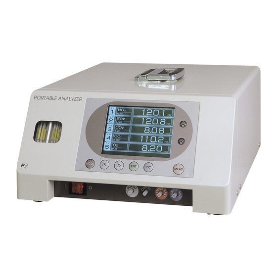
1. OVERVIEW The compact type gas analyzer with built-in pump and filter is intended for heat treat furnace, plant cultiva- tion, and research-purpose chemical analysis. With the gas extractor, either simplified measurement probe (non-fixed type) or continuous measurement probe (fixed type) is selectable at option. Since a high-sensitiv- ity single-beam mass flow controller is adopted for the infrared sensor, long-term stability and maintainabil- ity are excellent. -
Page 14: Outline Diagram
1.1 Outline diagram 1.1.1 Analyzing block (unit:mm) <Top view> <Side view> PORTABLE ANALYZER <Front view> <Rear view> PORTABLE ANALYZER Mass : Approx. 12kg - 2 - INZ-TN2ZSVS-E... -
Page 15: Power Cord And Signal Cable (Unit:mm)
1.1.2 Power cord and signal cable (unit:mm) • Power cord for domestic and North American use (North American type), rated voltage 125V AC. Note: The standards for domestic and North American use are different, but the shape is the same. (2000) •... -
Page 16: Non-Fixed Type Gas Extractor (Unit:mm)
• Control input/output cable (1000) 1.1.3 Non-fixed type gas extractor (unit:mm) (640) Gas inlet Sampling pipe Probe grip Specifications Probe cap Main materials of exhaust gas block: SUS304, ø6.5/ø4 hose band polypropylene, chloroprene rubber Mass: 0.5 kg - 4 - INZ-TN2ZSVS-E... -
Page 17: Fixed Type Gas Extractor (Unit:mm)
1.1.4 Fixed type gas extractor (unit:mm) Attached joint Sampling pipe 15A (ø21.7) RC 1 /2 4-ø12 Gas inlet Specifications Flange JIS 5K 25A FF Main materials of gas-contacting parts: SUS316, Teflon Mass: 1 kg Attached joint (for ø6 pipe connection) R1/2 ø4 Material : Teflon... -
Page 18: Sampling System Diagram
1.2 Sampling system diagram (1) With 1 optical system (1 to 3 component gas sampling system) Gas extractor Exhaust gas port analyzer Measurement cell Calibration gas inlet Purge gas port Filter Sample gas Membrane Pump inlet filter (2) With 2 optical systems (3 to 4 component gas sampling system) Gas extractor Exhaust... -
Page 19: Name Of Each Part And Descriptions
1.3 Name of each part and descriptions 1.3.1 Name of each part and descriptions (1) Analyzer unit (2) Flow checker (3) Display/operation unit (5) Power switch (4) Rubber foot (9) Calibration gas inlet (8) Sample gas inlet (7) Exhaust gas port (6) Purge gas inlet (1) Handle (16) Heat exhaust port... -
Page 20: Names Of External Connectors And Descriptions
1.3.2 Names of external connectors and descriptions <Analog output connector> Non-isolated linear connector for 4 to 20mA DC or Pin No. Description 0 to 1V DC Between 1 and 2 Ch1 analog output Output of up to 8 channels is allowed. Between 3 and 4 Ch2 analog output Output is made for corresponding channel No. -
Page 21: Operation Panel And Display
1.4 Operation panel and display This section provides the names of each key for operation and display screens, and describes details of their operation. 1.4.1 Names of parts on the operation panel and descriptions Display unit (7) Backligh UP key (8) Backlight DOWN key (1) MODE key (3) RIGHT key... -
Page 22: Outline Of Display Screen
1.4.2 Outline of display screen (1) Measurement mode screen (This screen appears immediately after the power is turned on.) The measurement 1 screen varies depending on the number of components. The measurement 2 screen is displayed for the specifications of 6 channels or more. The following screen configuration example is for 4-component specifications (CH , CO, and O ) (7 channels). - Page 23 • Instantaneous value and concentration value: The concentration display of Ch (component) where sampling components such as “CO ,” “CO” or “O are displayed in the component display, indicates current concentration values of the measured components contained in gas that is now under measurement. •...
- Page 24 (2) Menu mode screen The menu mode setting and select screen are shown below. Name Function Measurement 1 or measurement 2 screen (1) Status display Displays current status. (2) Message display Displays guideline for operation. MODE (3) Setting/select item Select settings or select items to be changed or checked using the cursor.
-
Page 25: Before Use
2. BEFORE USE DANGER This unit is not explosion-proof type. Do not use it in a place with explosive gases to prevent explo- sion, fire or other serious accidents. CAUTION • Entrust the installation, movement or re-installation to a specialist or the supplier. A poor installa- tion may cause accidental tipover, shock hazard, fire, injury, etc. -
Page 26: Piping In The Gas Analyzer
2.2 Piping in the gas analyzer 2.2.1 Piping procedure Sample gas inlet Gas extractor Gas tube About 30° Caution on piping • Use “Teflon” gas tube, which is low in adsorptive activity. Tilt the gas tube that connects the gas extractor and the analyzer unit by about 30° to prevent drain from staying within the tube. - Page 27 The probe handle consists of packing for probe, case, and relay packing. Connect the probe handle, probe cap, and gas tube, following the procedure shown below. 1) Check that the relay packing is inserted properly. Packing for probe Relay packing Probe cap Case Probe handle...
-
Page 28: Wiring
• If noise comes in from the power supply, mount a barrister (such as ENA211-1 by Fuji Electric) or a spark killer (such as S1201 Noise emission by OKAYA) to the noise emission source as shown by the figure source at right. -
Page 29: Output Connector
2.3.2 Output connector (1) Analog output • Use supplied dedicated cable (DB-25P 25 male pin) for taking out output signals. Fasten the cable securely using supplied screws. Output signal: 4 to 20mA DC or 0 to 1V DC (by code symbols), non-isolated Permissible load: 4 to 20mA DC, 550Ω... -
Page 30: Operation
3. OPERATION 3.1 Warm-up operation (1) Set power switch to ON. (“|”: ON, “ ”: OFF). The lamp within the power switch comes on. Power supply switch “ON” Caution on operation (2) The WARM-UP display comes on and stays on for about 2 seconds in the center. -
Page 31: Zero/Span Calibration
3.2 Zero/span calibration Be sure to perform zero/span calibration of each component after the warm-up operation is completed. 3.2.1 Zero calibration time and span concentration value setting (See “4.1.2” for setting method.) (1) Zero calibration time 1) Select <Menu Mode> → <2. Setting about Calibration> → <1. About Zero Calibration>, and select zero gas flow time. -
Page 32: Starting And Exiting Measurement
3.3 Starting and exiting measurement Perform measurement after zero/span calibration is completed. 3.3.1 Starting measurement (1) Display measurement 1 screen or measurement 2 screen. (2) Press the key, and the pump is started to suck the gas from the sample gas inlet. Caution on operation •... -
Page 33: Stopping Operation
3.3.3 Stopping operation Set the power to OFF after performing the following operations. (1) Purging of the sample gas line Remove the pipe connected to the sample gas inlet. Set the key to ON, and suck the air for 10 minutes or longer. When the reading returns to around zero (excluding O meter), press the key again. -
Page 34: Setting And Mode
4. SETTING AND MODE 4.1 Menu mode 4.1.1 Zero/span calibration Perform zero and span calibrations in the menu mode. Caution on operation • If zero/span calibration is attempted during warm-up operation, WARM-UP is displayed on the upper right-hand corner of the screen, and the calibration cannot be executed. •... - Page 35 <In the case of Air> <In the case of Dry N > Caution on operation • If O analyzer is provided, even if “ON” is selected for O zero calibration, calibration is not performed because O is contained in the zero gas.
- Page 36 Zero calibration of O analyzer 1. When <Dry N2> is selected in zero calibration mode (1) Calibration is performed simultaneously with the infrared ray sensor. See 4.1.1 (1) Zero calibration mode. 2. When <Air> is selected in zero calibration mode CAUTION •...
- Page 37 (2) Span calibration mode Caution on operation • When span calibration of the target Ch is completed, the screen automatically switches to the span calibration screen of the next Ch. Press the key not to perform span calibration, and the screen switches to the span calibration screen of the next Ch. Setting contents “both”...
- Page 38 Operation in the case where “each” is selected 1) Select “each” for calibration operation using the key, and press the key. 2) The cursor and concentration value are displayed only for the target range. Span calibration concentration value is also displayed at the bottom of the screen.
- Page 39 (3) Zero/span calibration complete screen 1) Exiting zero/span calibration in progress • If span calibration mode is jumped using the (calibration not performed), the “Menu Mode” screen appears again. MODE • If span calibration is executed by pressing key, the “Measurement screen” appears again.
-
Page 40: Setting Zero Calibration Time And Span Concentration Value
4.1.2 Setting zero calibration time and span concentration value (1) Setting zero calibration time Set the gas feed time for zero calibration. Setting range and contents • Zero gas feed time : “180 to 999 sec” (in steps of 1 sec) Initial value •... - Page 41 (2) Setting span calibration value Enter span calibration gas concentration value for each component and each range. Setting range • Minimum display value to full scale value (FS) of each range Note that the accuracy of span gas concentration value is guaranteed within 80 to 100% range of the full scale.
- Page 42 4) Select a digit using the key, and change the value using the key. Press the key. The previous screen appears again. Setting complete 5) Make the setting for other components and ranges in the same manner. The setting has now been completed. - 30 - INZ-TN2ZSVS-E...
-
Page 43: Setting Gas Change Time
4.1.3 Setting gas change time Change gas is automatically fed when calibration is completed during measurement. The duration of feed can be set as follows. Description of gas change • Gas change : After calibration is completed during measurement, sample gas is fed for a period of time arbitrarily selected. -
Page 44: Switching Ranges
4.1.4 Switching ranges The range and the display selected in this mode is output. The correction value, the average correction value and CP calculation value are also calculated in selection range. Initial value • “Minimum range” 1) Move the cursor to <4. Changeover of Range> using key, and press the key. -
Page 45: Canceling Errors
4.1.5 Canceling errors The error display can be canceled in this mode. Caution on handling • The error display only can be deleted in this mode. If the cause of occurrence of the error is not removed, the error display appears again. (1) Move the cursor to <6. -
Page 46: Setting Cp Calculation Value Conditions
4.1.6 Setting CP calculation value conditions Set the conditions necessary for CP calculation in this mode. Caution on handling • The mode is displayed when CP calculation value is selected for the output type. Setting range • CO concentration : Regular value; “10.0 to 40.0% CO” (In steps of 0.1%) •... - Page 47 The setting has now been completed. (Regular value) (2) Furnace temperature setting Enter temporary furnace temperature value. 2) Move the cursor to <2. Furnace Tempera- ture Setting> using the key and then press the key, and the screen is switched. 3) Select a digit using the key and change the value using the...
-
Page 48: Parameter Setting
4.1.7 Parameter setting The parameter setting screen can be entered in this mode. See 4.2 for details of parameter setting. (1) Move the cursor to <7. Parameter Setting> using the key, and press the key. The Parameter Mode screen appears. - 36 - INZ-TN2ZSVS-E... -
Page 49: Parameter Mode
4.2 Parameter mode Make the parameter setting, observing the following. Setting item • Current Date/Time : Set current month, date, hour, and minute. • Key Lock : Key operations can be disabled. • Output Hold : The output can be held during calibration in measurement. •... -
Page 50: Setting Date/Time
4.2.1 Setting date/time The setting is made to record the date and time of occurrence of an error. See <Maintenance Mode> → <13. Error Log> for the contents to be recorded. Caution on handling • This mode is backed up with a battery. However, if the power is kept off for 7 days or longer, the clock is made to stop. -
Page 51: Key Lock
4.2.2 Key lock The key lock function can be used to prevent improper operation and entry by an unauthorized person. Setting contents Initial value • ON : Enables key lock. • OFF • OFF : Resets key lock. Caution on setting •... -
Page 52: Output Hold
4.2.3 Output hold Output signals are put to hold during calibration in measurement (zero and span calibrations), and gas change. Setting contents Initial value • ON : Holds output signals. • OFF • OFF : Resets the hold of output signals. 1. - Page 53 (1) Move the cursor to <Output Hold> using the key, and then press the key. The cursor moves to the value to be entered. (2) Select “ON/OFF” using the key. (3) Press the key to register the setting. The item selection screen appears again. The setting has now been completed.
-
Page 54: Resetting Average Output Value
4.2.4 Resetting average output value Integrated average output value and display can be reset as follows. Caution on operation • Immediately after the reset is “execute,” the reading and the output value appear as 0ppm, vol%. • Reset is allowed only for the instrument of specifications with average value output provided. -
Page 55: Setting Indicator Lamp Off Time
4.2.5 Setting indicator lamp OFF time Automatic ON/OFF and OFF time of the indicator backlight can be set as follows. OFF condition • Set the setting to “ON.” • When the set time elapses since any key is pressed last on “measurement 1 screen or measure- ment 2 screen”... -
Page 56: Maintenance Mode
4.2.6 Maintenance mode Enter the password to go into the maintenance mode. Initial password • The password is set to “0000” at the time of delivery from the factory. • Select <Maintenance Mode> → <10. Password Set> to change the password. (1) Move the cursor to <Maintenance Mode>... -
Page 57: Maintenance Mode
4.3 Maintenance mode Change of output value, periodic inspection, and failure analysis are performed in the maintenance mode. See 4.2.6 Maintenance Mode for the procedure to enter the maintenance mode. Description of setting item 1. CH No. : Select “corrected instantaneous value” or “corrected average value” or “CP calculation value”... -
Page 58: Selecting Output Type
4.3.1 Selecting output type Instantaneous correction value or average correction value or CP calculation value can be selected in this mode. Caution on setting • Setting can be made only when CO, and CO (CO calculation value) analyzers are added for measured components. -
Page 59: Average Output Time
4.3.2 Average output time Average corrected time can be set in this mode. Caution on setting • The message shown at right is displayed if average cor- rected value is not selected in “4.3.1 Selecting output type.” • Sampling cycle is 30 seconds. •... -
Page 60: Selecting Output
4.3.3 Selecting output Current output (4 to 20mA DC) or voltage output (0 to 1V DC) can be selected in this mode. To switch between current and voltage outputs, switch the jumper pin of the control printed board. Caution on setting •... - Page 61 (1) Move the cursor to <3. Current/Volt> using the key, and press the key. The screen switches as shown at right. (2) Move the cursor to the output to be selected using the or the key. Press the , and the cursor moves to the value to be entered.
-
Page 62: Adjusting Output
4.3.4 Adjusting output Zero value and span value of output signals can be adjusted as follows. Preparation for the setting • Connect an ammeter or a voltmeter to the analog output connector. Caution on setting Tolerance of output value • The variable setting value is for internal •... -
Page 63: Setting O Reference Value
4.3.5 Setting O reference value Reference O correction concentration value can be set to obtain O correction concentration value. Caution on setting • Valid only when CO analyzer is added. • If O analyzer is not added, the message shown at right is displayed. -
Page 64: Adjusting Moisture Interference (Targeted For No And So Analyzers Of Special Specifications)
4.3.6 Adjusting moisture interference (Targeted for NO and SO analyz- ers of special specifications) The moisture interference adjustment is for NO and SO analyzers only, and is not performed in general situations. This is an adjustment mode for correcting the effect of moisture interference. See “5.3.3 Interface”... - Page 65 (3) Feed the moisture interference gas using the key. Press the key, and the cursor moves to the correc- tion value. (4) When the interference value stabilizes, enter correction value using the (UP) key, (DOWN) key, and (digit) key so that the interference value becomes 0.
-
Page 66: Setting Transmission Station No
4.3.7 Setting transmission station No. The station No. for Modbus communication can be set as follows. Caution on use • Establish communication program separately, referring to a separate document “Communication Function.” Setting range Initial value “01 to 31” “01” (1) Move the cursor to <7. Station No.> using the key, and press the key. -
Page 67: Response Time
4.3.8 Response time Response time by internal operation (moving average) can be set as follows. Caution on use • The set time is for guidelines. • The response time set here does not include gas feed and gas change time. •... -
Page 68: Minus Display
4.3.9 Minus display The function turns minus reading into “0.” Setting contents • ON : Outputs minus reading. (Outputs minus values.) • OFF : Does not output minus reading. (Does not output minus values.) * The same applies to concentration value display. Initial value “OFF”... -
Page 69: Password Setting
4.3.10 Password setting The password for moving from <Parameter Mode> to <Maintenance Mode> can be set as follows. Caution on setting • Be sure to record and store your established password just in case you forget it. Setting range Initial value “0000 to 9999”... -
Page 70: Sensor Input
4.3.11 Sensor input The A/D conversion values of sensor input signals can be displayed. Description of the screen • Sensor : Displays sensor components. • Input value : Displays the values immedi- ately after A/D conversion in count values. Input value Sensor Caution on operation... -
Page 71: Checking Coefficient
4.3.12 Checking coefficient Internal operation coefficient of “offset value” and “zero/span correction value” can be checked in this mode. Caution on operation • This mode is for checking the coefficient. Entry by key operation is not allowed. (1) Move the cursor to <12. Coeffi- cient>... -
Page 72: Error Log File
4.3.13 Error log file The error code history can be checked in this mode. Description of the screen • History: Displays error No. Data and time occurrence • Date of occurrence: Component where Displays the date and time of the error occurred occurrence of the error •... -
Page 73: Factory Mode
4.3.14 Factory mode You can enter the factory mode, but you need not carry out adjustment or setting. Description of the screen • Changing the data in the factory mode may cause malfunction of the instrument. Do not change the data in factory mode by yourself. •... -
Page 74: Inspection And Maintenance
5. INSPECTION AND MAINTENANCE 5.1 Daily inspection (Be sure to perform daily.) Inspection Judgment criteria Judgment criteria Name of unit Flow rate Check that the flow rate falls within the specified The ball is kept at the Flow checker check range. -
Page 75: Maintaining Analyzer Unit
5.3 Maintaining analyzer unit 5.3.1 Internal composition of analyzer unit See separate “Service Manual” for internal composition and replacement/adjustment of repair parts. 5.3.2 Replacing power fuse Caution on replacement • Be sure to remove the power cable before starting the work. •... -
Page 76: Adjusting Moisture Interference (Targeted For No And So Analyzers Of Special Specifications)
5.3.3 Adjusting moisture interference (Targeted for NO and SO analyz- ers of special specifications) Since the compact type gas analyzer performs measurements, using specific wave range of infrared ray, moisture wavelength over the entire wave range interferes with the measurement, thus causing reading error. - Page 77 (2) Adjusting moisture interference (Manual adjustment) Follow the procedure shown below to manually adjust the interference. 1) Directly feed dry N or dry Air gas to the sample gas inlet at the rate of 0.5L/min. (Adjust the gas flow rate so that the flow checker ball comes to the center.) 2) Select <Dry N >...
-
Page 78: Replacing Galvanic O Sensor (When Provided With The Sensor)
5.3.4 Replacing galvanic O sensor (when provided with the sensor) The service life of this sensor is about 18 months from the date of delivery. We recommend periodic replacement of the sensor. Replacement parts order No.: TK7M3502C1 (1) Remove the screws (M4 × 7 pcs.) on the rear and the side faces of the main unit. -
Page 79: Replacing Filter Within The Analyzer Unit
5.3.5 Replacing filter within the analyzer unit Periodic replacement of this filter is not required. Replace the filter if drain flows into the filter or clogging by dust is found. Replacement parts order No.: TK7L8925P1 (1) Remove the cover by referring to 5.4.4. (2) Remove the filter attached to sample gas inlet (case color: blue). -
Page 80: Replacing Filter Paper Of Membrane Filter
5.3.6 Replacing filter paper of membrane filter Replacement parts order No.: TK700735P2 (Filter paper: Glass fiber) 8553765 (Large O-ring) TK733572P1 (Small O-ring) Open Close (1) Replacing filter paper 1) Turn the lid of the membrane filter counterclockwise. 2) Remove the small O-ring, and then remove the contami- nated filter paper. -
Page 81: Replacing Diaphragm
5.3.7 Replacing diaphragm Replacement parts order No.: TK713248P1 Gas aspirator Hose band (1) The gas aspirator is fixed on the baseboard with Hose band nuts (M3 × 4 pcs.) Pipe Pipe Remove the nuts and then take the gas aspirator out of the main unit. -
Page 82: Cleaning Measurement Cell
5.3.8 Cleaning measurement cell Entry of dust or water drops into the measurement cell may cause internal contamination, which may result in drifting. Be sure to clean the measurement cell if contamination is found. At the same time, check the filter in particular, to prevent the entry of dust or mist into the cell. Two types of cells are available for measurement, namely, the block cell (length: 4mm, 8mm, 16mm, 32mm) and the pipe cell (length: 64mm, 125mm, 250mm). - Page 83 Name Screw (for fastening light source unit) Screw (for fastening detector) Screw (for fastening base plate) Base plate Infrared ray light source unit Screw (for fastening support) Screw (for fastening cell presser) Connector for chopper motor Filter Support Cell presser Pipe cell O-ring Window...
- Page 84 (2) Cleaning the block cell (See Fig. 5-2) 1) Stop feeding the gas for measurement. If toxic gas is contained, purge the measurement cell fully with zero gas. 2) Turn off the power switch. 3) Remove the pipe connected to the measurement cell. 4) Remove the connector of the detector from the printed board.
- Page 85 Name Screw (for fastening light source unit) Filter Screw (for fastening base board) Base board Infrared ray light source unit Screw (for fastening block cell) Block cell Window O-ring Screw (for fastening detector) Connector for chopper motor Detector (13) Detector: For 2-component analyzer, Mounting (14) Screw: For mounting 2-component detector (14)
-
Page 86: How To Mount Pressure Regulator For Standard Gas Cylinder
5.3.9 How to mount pressure regulator for standard gas cylinder (1) Before mounting a pressure regulator to the gas cylinder, clean the gas cylinder adapter. Entry of dust into the pressure regulator may result in gas leaks. (2) If packing is not inserted in the mounting nut for the cylinder or it is damaged, replace it with supplied spare one. -
Page 87: Airtight Test
5.4 Airtight test Perform an airtight test following the procedure shown below. Set the power switch to OFF, and perform airtight test for the analyzer unit and the sampling unit separately. 5.4.1 Airtight test of analyzer unit (1) Close the exhaust gas port (OUTLET). (2) Connect the sample gas inlet and calibration gas inlet with a T tube. -
Page 88: Adjustment In Heat Treatment Furnace
5.5 Adjustment in heat treatment furnace • What is the adjustment in heat treatment furnaces? If, in plant gases to be measured actually, a large amount of other lower-molecular-weigh gases than nitrogen (N ) such as hydrogen (H ), or a large amount of other higher-molecular-weight gases than nitrogen (N ) such as argon (Ar) are contained, including the measuring components, it is known that the calibration curve (output performance to gas concentration) of gas analyzers will be affected (pres-... - Page 89 (2) Method for span calibration by check gas The method for span calibration by use of check gas (give in 2) is explained. Since span calibration has an error of calibration curve, preset a calibration indication on the calibration curve graph attached to this analyzer for indirect calibration.
-
Page 90: Spare Parts
6. SPARE PARTS CAUTION • Do not use replacement parts other than recommended ones. Otherwise, it could result in accident or damage to the instrument. • Useless replacement parts for maintenance should be disposed of as non-combustible matter. 6.1 Spare parts for 1-year measurement (1) List of spare parts for one year Note: The replacement cycle varies depending on the conditions of the measured gas. -
Page 91: Troubleshooting
7. TROUBLESHOOTING CAUTION • In case you find it difficult to judge what happened to the instrument, avoid disassembling the instrument without consulting our sales agent or service engineers. Otherwise, it may result in electrical shock or personal injury. Phenomena Items Check Remedy... - Page 92 Error message If errors occur, the following contents are displayed. Error display Error contents Probable causes Error No.1 Motor rotation detection signal • Motor rotation is faulty or stopped. faulty • Motor rotation detector circuit is faulty. Error No.4 Zero calibration is not within. •...
- Page 93 (2) In case of Error No. 5 and No. 7 Calibration is continued. Unless another calibration error occurs, calibration is carried out to the end, the Measurement screen returns. Error log file If error occurs, the history is saved in an error log file. The error log file exists in the maintenance mode.
-
Page 94: Specification
8. SPECIFICATION This product is not explosion-proof. When handling dangerous gas, adequate attention shall be paid. 8.1 Specification Standard Specifications • Measuring system: • Indicated values: , CO and CH ; Non-dispersive infra- Digital 4-digit indication (by LCD with back red absorption method with single light light) source and single beam (single beam... - Page 95 • CP calculation: The carbon potential of carburizing fur- Standard Function nace and conversion furnace are calcu- lated using furnace temperature (fixed • Zero gas flow time: input value) and CO concentration value 180 to 999 sec (settable in 1-sec step) (fixed or measured value) while referring •...
- Page 96 Standard Requirements for Sample Gas Scope of Delivery 0.5 L/min ±0.2 L/min • Flow rate: • Gas analyzer system • Temperature: 0 to 40˚C at inlet of sampling gas • Standard accessories (Refer to the table at top Following 10 to 70˚C at tip of non-fixed type probe table.) (available at option) •...
-
Page 97: Code Symbols
8.2 Code symbols Digit No. 1 2 3 4 5 6 7 9 10 11 12 13 14 15 16 17 18 19 20 Z S V of code Digit Description note < Specification > Analyzing block < Sample components (CO , CO, CH ) >... - Page 98 Digit No. 1 2 3 4 5 6 7 9 10 11 12 13 14 15 16 17 18 19 20 Z S V of code Digit Description note < Output > 0 to 1 V DC, non-isolated 4 to 20 mA DC, non-isolated note 5,7 <...
- Page 99 Tables of Sample Component and Measuring Range - Availability Check Tables - Table 1: 1-Component Analyzer (CO , CO, CH Sample component analyzer CO analyzer analyzer Range 0 to 200/500/1000ppm 0 to 500/1000/2000ppm 0 to 1000/2000/5000ppm 0 to 2000/5000ppm/1% 0 to 5000ppm/1/2% 0 to 1/2/5% 0 to 2/5/10% 0 to 5/10/20%...
- Page 100 Table 4: 2-Component Analyzer (CO analyzer + CH analyzer) analyzer Range values are the same as those of CO analyzer. range analyzer range 0 to 200/500/1000ppm 0 to 500/1000/2000ppm 0 to 1000/2000/5000ppm 0 to 2000/5000ppm/1% 0 to 5000ppm/1/2% 0 to 1/2/5% 0 to 2/5/10% 0 to 5/10/20% 0 to 10/20/50%...
- Page 101 robal Sales Section Instrumentation & Sensors Planning Dept. , Fuji-machi, Hino-city, Tokyo 9 -8502, Japan http://www.fujielectric.com Phone: +8 -42-5 4-8930 Fax: +8 -42-583-8275 http://www.fujielectric.com/products/instruments/...
Need help?
Do you have a question about the ZSVS-2 and is the answer not in the manual?
Questions and answers