Table of Contents
Advertisement
Quick Links
Advertisement
Table of Contents

Related Manuals for Fuji Electric ZPA


Summary of Contents for Fuji Electric ZPA
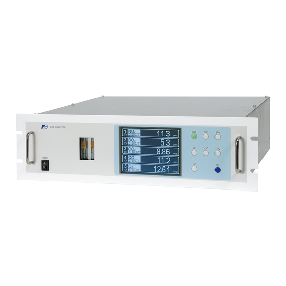
- Page 1 Service Manual INFRARED GAS ANALYZER TYPE: ZPA, ZPB, ZPG INZ-TN5A1191a-E...
- Page 2 This service manual is intended for use with the instruction manual to help you in understanding maintenance and inspection for the infrared gas analyzer (ZPA, ZPB, ZPG). However, the basic operation of the analyzer is not covered in this manual.
-
Page 3: Table Of Contents
(1) Analyzer main unit (External/internal) ....................1 (2) Optical unit............................3 (3) Connection of parts ..........................6 1) Wiring diagram (ZPA) ........................6 2) Wiring diagram (ZPB) ........................7 3) Wiring diagram (ZPG)........................8 4) Internal piping diagram (ZPA)......................9 5) Internal piping diagram (ZPB)....................... - Page 4 4) Readings are high or low too much....................27 5) Readings are not increased ......................27 (2) Data sampling at trouble ........................28 6. ADJUSTMENT IN HEAT TREATMENT FURNACE.............29 (1) Method for span calibration by standard gas with the same composition as plant gas.....29 (2) Method for span calibration by check gas ..................30 7.
-
Page 5: Caution On Safety
CAUTION ON SAFETY First of all, read this “Caution on safety” carefully, and then use the analyzer in the correct way The cautionary descriptions listed here contain important information about safety, so they should always be observed. Those safety precautions are ranked in 3 levels, “DANGER”, “CAUTION” and “PROHIBITION”... - Page 6 Caution on piping In piping, the following precautions should be observed. Wrong piping may cause gas leakage. If the leaking gas contains a toxic component, there is a risk of serious accident being induced. Also, if combustible gas is contained, there is a danger of explosion, fire or the like occurring.
- Page 7 If the cause of any fault cannot be determined despite reference to the AUTION instruction manual, be sure to contact your dealer or Fuji Electric’s technician in charge of adjustment. If the analyzer is disassembled carelessly, you may have a shock hazard or injury.
-
Page 8: Structure Of Analyzer And Names Of Parts
1. STRUCTURE OF ANALYZER AND NAMES OF PARTS (1) Analyzer main unit (External/internal) TN5A1191-E... - Page 9 Mount or not Part No. Part name Case ass’y Base Front panel ass’y Solenoid Valve (SV) ass’y none Power supply mounting plate Handle Paramagnetic type O sensor unit Power switch Pipe fuse Fuse holder Noise filter Power inlet terminal Power inlet Key board Triple gas port unit Dust cap...
-
Page 10: Optical Unit
(2) Optical unit TN5A1191-E... - Page 11 TN5A1191-E...
- Page 12 Part No. Part name Part No. Part name Light source unit Cell fixing block LS power board Block cell ass’y Pipe cell ass’y Window ass’y Window ass’y Block cell O ring Gas filter Pipe cell Filter Cell mounting Detector unit Base plate TN5A1191-E...
-
Page 13: Connection Of Parts
(3) Connection of parts 1) Wiring diagram (ZPA) TN5A1191-E... -
Page 14: Wiring Diagram (Zpb)
2) Wiring diagram (ZPB) TN5A1191-E... -
Page 15: Wiring Diagram (Zpg)
3) Wiring diagram (ZPG) TN5A1191-E... -
Page 16: Internal Piping Diagram (Zpa)
4) Internal piping diagram (ZPA) Optical unit 2 (IR Unit 2) Optical unit 1 (IR Unit 1) Built-in sensor INLET1 OUTLET1 Sampling gas outlet Sampling cell Note) Sampling gas inlet 2 cells may be used by combination of measuring component. -
Page 17: Internal Piping Diagram (Zpb)
5) Internal piping diagram (ZPB) Optical unit 2 (IR Unit 2) Optical unit 1 (IR Unit 1) (Left) (Right) Built-in sensor Sampling cell REFERENCE INLET1 OUTLET1 Note) 2 cells may be used Sampling gas inlet Sampling gas and by combination of reference gas outlet measuring Reference gas inlet... -
Page 18: Internal Piping Diagram (Zpg)
6) Internal piping diagram (ZPG) Sampling cell Optical unit 1 (IR Unit 1) (Left) (Right) Built-in sensor REFERENCE INLET1 OUTLET1 Sampling gas inlet Sampling gas outlet and reference gas outlet Reference gas inlet Correspondence of measuring components and optical units Measuring components Optical unit 1 Optical unit 2... -
Page 19: Maintenance And Inspection, And Repair And Adjustment At Replacement Of Measuring Units
Measure resistance between 2-pin terminals at the light source, and the resistance value must be 36.5 ±2 (for ZPA, ZPB and ZPG-CO ) or 6.2 ±0.3 (for ZPG-NO,SO and CO). If resistance values are infinite, the light source may be broken. -
Page 20: Cell, Cell Window And O-Ring
35,000 to 55,000 (ZPA) or 350,000 to 550,000 (ZPB & ZPG) when zero gas is supplied. If the counter value is below the range, sensitivity can be degraded. -
Page 21: Built-In O Sensor (Paramagnetic Type)
2) Measures : Replace detector. Precautions on replacement: The Amplifier board is set according to the specificaions of each detector. When ordering, notify analyzer serial number, detector serial number and the detector type (ex. “NO-H”). So the Amplifier board has suitable gain in it. 3) Replacement When a cell is a block cell, remove the light source motor unit. -
Page 22: Sensor (Galvanic Cell Type)
(6) Built-in O sensor (galvanic cell type) Recommended period of replacement : 2 years Error mode : Sensor deterioration. Phenomena : Span drift and fluctuation in indication by sensitivity deterioration. Check : Same as Built-in O sensor (paramagnetic type). Refer to (5) Check shown above.or Measures : Same as Built-in O... -
Page 23: Main Power Board
: check the voltage shown below. Check terminal Check voltage Contents VIN-GND1 common for +24.0±1.0 V (Input voltage) ZPA, ZPB and ZPG VOUT-GND2 +15.0±0.5 V for ZPA and ZPB (Output voltage) +9.0±0.5 V for ZPG Adjustment after replacement : check the voltage shown above. -
Page 24: Power Supply
: Turn OFF the analyzer power. Disconnect the cable from the Main board and replace it with a new one. Check after replacement : Check the power supply voltage on the Main board. ZWS50BAF-24 (common for ZPA, ZPB & ZPG) 部品面 CN51 入力... -
Page 25: Operation Parts
(10) Operation Parts Error mode : Wear on switching Phenomena : Faulty operation Check : Be sure to turn OFF the main unit power supply before inspecting. 1) Remove the cable. 2) Measure the resistance for connector pin No. of switch that does not function with a tester (see Allocation of Connector Table). -
Page 26: Solenoid Valve
(11) Solenoid valve Recommended period of replacement : 3 years Error mode : Short-circuit by burning out breaking of wire exhaustion of core Phenomena : Indication decrease to 0ppm. Transition sound disappear. Measures : Replace Solenoid valve ass’y. Replacement : Turn OFF the analyzer main unit. Disconnect the connector, piping and replace it with a new one. -
Page 27: Factory Mode
3. FACTORY MODE (1) How to go to factory mode Maintenance Select operating item Point the cursor to “6. To Factory Mode” by using the Mode key on the Maintenance Mode screen and enter the key. Then, the password input screen appears. 1. Sensor Input Value 2. Error Log 3. Cal. Log... -
Page 28: Setting Change Items
(2) Setting change items 1) Zero limit Function: Switches measured concentration values below zero to either display or no display mode. Operation method: Changes the setting in “Factory mode”, “12. Others” and “Zero limit”. Factory mode initial screen The cursor is in 12. Set values are inverted by pressing the key, when the cursor is aligned with the “Zero limit”. -
Page 29: Range Limit
2) Range limit Function : Measured concentration values used for O correction or moving average computation can be switched to either with limiter (upper limit 110%F.S.) or without limiter (the graph within the panel). Operation method: Changes the setting in “Factory mode”, “12. Others” and “Zero limit”. Factory mode initial screen The cursor is in 12. -
Page 30: Calibration Coefficient
3) Calibration coefficient Function: Displays calibration coefficient. Operation: The coefficient initial screen is as shown at right. Factory mode initial screen The cursor is in 14. R1 and R2 represent range 1 and 2. Zero calibration coefficient is displayed on the left side of screen, and span calibration coefficient is displayed on the right side. -
Page 31: Setting Value Reference Items
When supplying zero gas (dry); No. 0 (Infrared ray component 1) 35,000 to 55,000 (ZPA) or 350,000 to 550,000 (ZPB & ZPG) No. 1 (Infrared ray component 2) 35,000 to 55,000 (ZPA) or 350,000 to 550,000 (ZPB & ZPG) No. -
Page 32: Error Judgement Criteria For Error Codes
A/D conversion, error occurs. A/D conversion values (counter values) can be checked by the counter indication when the Factory mode screen is displayed. 35,000 No. 15 55,000 (ZPA) or 350,000 No. 15 550,000 (ZPB & ZPG) Error 4 Zero calibration is not Infrared component: 0.5... - Page 33 Main portions to be checked during error Error No. Main portions to be checked Error 1 Sector rotation, light source, and detector signal on amplifier printed circuit board. Error 2 See service manual No.17 to 20 in “1) A/D data” on the page 24. Connecting part between detector amplifier board and Main board (cable connector).
-
Page 34: Troubleshooting And Data Collection
5. TROUBLESHOOTING AND DATA COLLECTION (1) Countermeasures against trouble 1) Zero calibration can not be performed Check that a specified amount of zero gas is supplied to the analyzer main unit Locate a gas leaked portion and remedy. Check if detector signal is as specified (see Detector unit.). Check the voltage of detector. -
Page 35: Data Sampling At Trouble
(2) Data sampling at trouble When trouble occurs, be sure to sample the following data. In the case of the trouble in connection with the characteristic, please sample data (please surely sample data to a factory at the time of an inquiry). Supply the gas given in Table and sample the measured value of measurement screen, sensor input values in maintenance mode. -
Page 36: Adjustment In Heat Treatment Furnace
6. ADJUSTMENT IN HEAT TREATMENT FURNACE What is the adjustment in heat treatment furnaces? If, in plant gases to be measured actually, a large amount of other lower-molecular-weigh gases than nitrogen (N ) such as hydrogen (H ), or a large amount of other higher-molecular-weight gases than nitrogen (N ) such as argon (Ar) are contained, including the measuring components, it is known that the calibration curve (output performance to gas concentration) of gas analyzers will be affected (pressure broadening). -
Page 37: Method For Span Calibration By Check Gas
(2) Method for span calibration by check gas The method for span calibration by use of check gas (give in 2) is explained based on the example. (Since span calibration has an error of calibration curve, preset a calibration indication on the calibration curve graph attached to this analyzer for indirect calibration.) The following calibration curve graph is attached to the test results for the product. -
Page 38: Moisture Interference Adjustment (No, So Only)
7. Moisture interference adjustment (NO, SO only) Purpose : Adjust the light control plate in between the three layer detector so that moisture interference becomes close to zero. Light control plate Procedure : (1) To start adjustment, set the light control plate at the same height (10 to 15mm upper than (c): upper end of Fixing screw the fixing plate) as in the right figure (a). -
Page 39: Appendix 1. Measuring Principle Diagram
APPENDIX 1. MEASURING PRINCIPLE DIAGRAM Principle Diagram of Infrared Type Measurement (NO, SO , CO , CO, CH Front expansion chamber Gas inlet Gas outlet Infrared-ray light source Rear expansion chamber Detector Mass flow Motor Measurement cell sensor Chopper Preamplifier Indication Signal processing block... -
Page 40: Appendix 2. Soft Flow Diagram
APPENDIX 2. SOFT FLOW DIAGRAM TN5A1191-E... -
Page 41: Appendix 3. Printed Board Diagram
APPENDIX 3. PRINTED BOARD DIAGRAM Main board sensor gain switchover) External zirconia type O / built-in galvanic cell type O Built-in paramagnetic type O External input type O TPVH1 (3.3V) (Digital) TPVS1 (0V) TPVL1 (3.3V) (1.25V) (Digital ground) (AD integral waveform) (Backup battery) (Digital) Common with TPG 1... -
Page 42: Aio Board
AIO board Additional AO board 1 Additional AO board 2 (Ch1 Analog output selection) Short circuit between -2 : Current output CN10 (External O sensor input IN) Short circuit between 2-3 : Voltage output (External O sensor input OUT) (Ch2 Analog output selection) (To Main board) To DIO board, SSW board and JP1 to 4... -
Page 43: Main Power Board
Power supply 1 to Main board to LS power board 1 Digital to LS power board 2 (Digital ground) Light Source power board for ZPA and ZPB for ZPG to Light Source to Main power board VOUT GND1 GND2...
Need help?
Do you have a question about the ZPA and is the answer not in the manual?
Questions and answers