Table of Contents
Advertisement
Quick Links
Advertisement
Table of Contents

Related Manuals for Fuji Electric ZPAF


Summary of Contents for Fuji Electric ZPAF
- Page 1 Instruction Manual BIOMASS GAS ANALYZAR TYPE: ZPAF INZ-TN2ZPAF-E...
- Page 2 PREFACE Thank you very much for purchasing Fuji’s Infrared Gas Analyzer (Type: ZPAF). injury. Request INZ-TN2ZPAF-E...
-
Page 3: Caution On Safety
CAUTION ON SAFETY To operate the analyzer properly, be sure to read “Caution on Safety” carefully. DANGER CAUTION damage. PROHIBITION CAUTION Caution on installation and transport of gas analyzer DANGER CAUTION INZ-TN2ZPAF-E... - Page 4 Caution on piping Be sure to observe the following precautions while installing DANGER piping. Improper piping may result in gas leakage. If the leaking gas contains a toxic component, serious acci- dents may result. If it contains combustible gases, explosion Caution on wiring CAUTION INZ-TN2ZPAF-E...
- Page 5 Caution on use DANGER properly. sive. CAUTION Caution on use PROHIBITION INZ-TN2ZPAF-E...
- Page 6 Caution on maintenance and check DANGER Be sure to observe the following to perform work safely, CAUTION avoiding electric shock or injury. Others CAUTION INZ-TN2ZPAF-E...
- Page 7 CONTENTS ........................i ....................ii ......................... v ..............vii ................................................................................ 4 .................... 4 ......................5 ............... 5 ........................6 ....................................................................................................9 ..........9 ............................................................................................................................................................................................
- Page 8 ............................................................................................................................................................................................................................................................................................54 ....................55 ......................55 ............55 ..................56 ............................................................sensor ......................65 .................... 66 ..............................................................................
-
Page 9: Warranty And Maintenance
WARRANTY AND MAINTENANCE Scope of application Operating conditions and environment Precautions and prohibitions Warranty 4-1. Period of warranty 4-2. Scope of warranty place of purchase or delivery. viii INZ-TN2ZPAF-E... -
Page 10: Failure Diagnosis
Failure diagnosis Service life Maintenance plan Maintenance Preventive Daily inspection maintenance Periodic inspection Corrective Troubleshooting maintenance Limited-life parts and consumable parts INZ-TN2ZPAF-E... - Page 11 Spare parts and accessories 10. Period for repair and provision of spare parts after product dis- continuation (maintenance period) INZ-TN2ZPAF-E...
- Page 12 1. OVERVIEW INZ-TN2ZPAF-E...
-
Page 13: Name Of Delivered Items And Each Parts
2. NAME OF DELIVERED ITEMS AND EACH PARTS Analyzer: 1 unit Standard: IEC127-2 Size: ø5 × 20mm Fuse: 2 pcs Rating: 250V/2A delay type Part No.: R75796N17 25 pin D-sub connector (male) Analog output connector: 1 Part No.: R77256N262 Fixing screws: 2 M2.6 ×... -
Page 14: Name And Description Of Analyzer
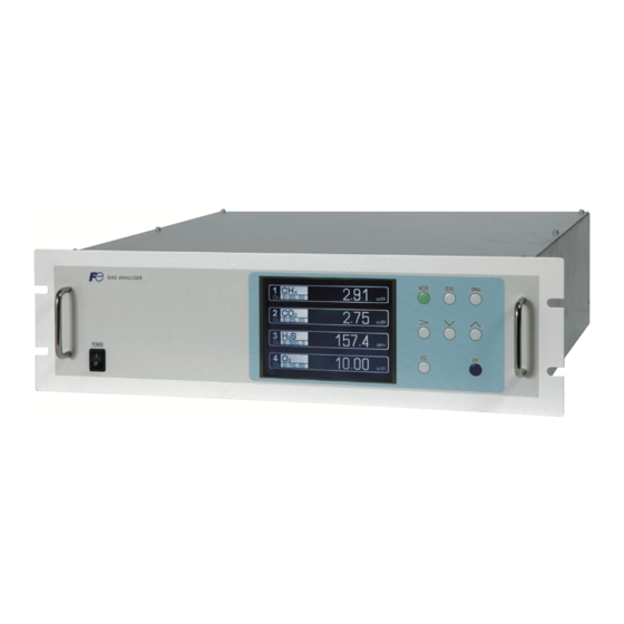
2.2 Name and description of analyzer (unit mm) < Front panel > (2) Display/operation panel (1) Power switch (12) Analog output connector (A / O) (D-sub25 pin) (3) Analyzer purge gas inlet (11) Communication connector (RS-485) (4) CH , CO inlet (5) CH , CO... -
Page 15: Installation Conditions
3. INSTALLATION DANGER CAUTION injury. 3.1 Installation conditions unit : mm analyzer (installed) analyzer (drawer out) INZ-TN2ZPAF-E... -
Page 16: Installation Of Analyzer Main Frame
3.2 Installation 3.2.1 Installation of analyzer main frame (Unit : mm) Type External dimensions Mounting dimensions Mounting method 19-inch rack mounting 450 or more Support “A” : 57.2 (EIA) INZ-TN2ZPAF-E... - Page 17 3.3 Piping coupling. Purge gas inlet , CO inlet S outlet , CO outlet Air inlet S inlet or less. INZ-TN2ZPAF-E...
- Page 18 Internal piping diagram Optical unit 1 Galvanic sensor <CO , CH > Constant-potential electrolytic S sensor S IN S OUT OUTLET1 INLET1 S inlet , CH inlet Purge gas inlet (for H , CH outlet Correspondence of measured components and optical units INZ-TN2ZPAF-E...
-
Page 19: Conditions Of Sampling Gas
3.4 Sampling 3.4.1 Conditions of sampling gas consider Note 3.4.3 Preparation of standard gas Zero gas INZ-TN2ZPAF-E... -
Page 20: Purging Of Instrument Inside
3.4.4 Purging of instrument inside 3.4.5 Pressure at sampling gas outlet and reference gas outlet Gas analyzer (ZPAF) (8) Membrane (7) Flowmeter filter (2) Gas aspirator S purge) Air for H S purge (2) Gas S Inlet Exhaust (1) Mist filter... - Page 21 3.5 Wiring CAUTION CAUTION Communication connector (RS-485) Analog output connector (A/O) Digital input/output connector (DIO 1 to 3) (1) Power supply (standard terminal 1 to 2) <Power inlet> Power socket Grounding 2-pole plug INZ-TN2ZPAF-E...
- Page 22 When noise source is in the vicinity Main unit power supply Varistor or spark quencher Install (connect) near the source. valves. Noise generating source (2) Analog output signal: Analog output connector (A/O) < Analog output > A/O connector AO1+ AO1- AO2+ AO2- AO3+...
- Page 23 (3) Contact input/output (DIO): digital input/output connector (DIO1 to 3) < Digital input/output > Connector for DIO 1 to 3 (option) DIO1 DIO2 DIO3 connector connector connector DI1+ DI4+ DI7+ DI1- DI4- DI7- Digital input DI2+ DI5+ DI8+ OFF : 0V DI2- DI5- DI8-...
- Page 24 (4) Communication: RS-485 connector < RS-485 connector > (GND) RT D+ RT D- D-sub 9-pin female (5) Timing of contact output for calibration 1) Manual calibration (See “Section 6.8 Calibration”.) (When the analyzer has auto calibra- tion function.) INZ-TN2ZPAF-E...
- Page 25 2) Automatic calibration (example shown in Section 6.4.1, Auto calibration) Automatic Ch1 span Ch3 span calibration calibration calibration start Ch4 span Ch2 span Zero calibration calibration calibration Zero gas Zero calibration output 350 s Ch1 span calibration output Ch1 span gas 350 s Ch2 span calibration output Ch3 span calibration output...
-
Page 26: Preparation For Operation
4. OPERATION 4.1 Preparation for operation (1) Tube and wiring check 4.2 Warm-up operation and regular operation (1) Operation procedure Note) During warm-up, the display indicates midline horizontal bars. This is not an error. INZ-TN2ZPAF-E... -
Page 27: Description Of Display And Operation Panels
5. DESCRIPTION OF DISPLAY AND OPERATION PANELS 5.1 Name and description of operation panel Display unit Operation panel (7) ZERO key (8) SPAN key MODE ZERO SPAN (1) MODE key (4) DOWN key (2) SIDE key (3) UP key (5) ESC key Name Description Name... -
Page 28: Overview Of Display And Operation Panels
5.2 Overview of display and operation panels INZ-TN2ZPAF-E... -
Page 29: Outline Of Display Screen
5.3 Outline of display screen (1) Measurement mode screen (appears when the power is turned ON) 0-20.00 vol% 0-20.00 vol% 0.0 0 0-500 0-10 vol% Instantaneous value and concentration value: INZ-TN2ZPAF-E... - Page 30 (2) Setting/selection screen Message display area Status display area display area Cursor (3) Contents of measured channel (Ch) Code Display and output Ch1: H Ch1: H S, Ch2: O Ch1: CO , Ch2: H Ch1: CO , Ch2: H S, Ch3: O Ch1: CH , Ch2: H Ch1: CH...
-
Page 31: Basic Operation
5.4 Basic operation ZERO C h 0-20.00 vol% Zero calibration C h See 6.8.1. 0-20.00 vol% 0.0 0 C h Span calibration 0-500 See 6.8.2. C h 0-10 vol% SPAN User Mode Select an item with UP/DOWN and ENT Back with ESC Switch Ranges Calibration Parameters Alarm Setting Setting of Auto Calibration... -
Page 32: Setting And Calibration
6. SETTING AND CALIBRATION 6.1 Switch of range 6.1.1 Setting of range switch mode MODE User Mode Select an item MODE with UP/DOWN and ENT Back with ESC Switch Ranges Calibration Parameters key. Alarm Setting Setting of Auto Calibration Setting of Auto Zero Calibration Parameter Setting Switch Range Select Ch No. -
Page 33: Manual Range Switch
6.1.2 Manual range switch Switch Range Select Ch No. Switch ranges with UP/DOWN and ENT Back with ESC key. Range1 0–20.00 vol% Range2 0–100.0 vol% Range1 0–20.00 vol% Range2 0–100.0 vol% Range1 0–500.0 Range2 0–2000 Range1 0–10.00 vol% Range2 0–25.00 vol% Switch Range Select Ch No. -
Page 34: Setting Of Calibration Concentration
6.2 Calibration setting Cal. Parameters Select an item with UP/DOWN and ENT Back with ESC Calibration Value 6.2.1 Setting of calibration concentration About ZERO Calibration About Calibration Range About Calibration Components / Range Cal. Settings Select Ch No. Cal. Value for Setting calibration value RANGE ZERO... - Page 35 Cursor for setting value Cal. Settings Set calibration value Cal. Value RANGE ZERO SPAN 0–20.00vol% +0000.0 0020.00 0–100.0vol% +00000 0100.00 0–20.00vol% +0000.0 0020.00 Note) Enter settings that correspond to 0–100.0vol% +00000 01000.0 each range. If zirconia type is used 0–500.0ppm +000.00 0500.00 as O...
-
Page 36: Setting Of Manual Zero Calibration
6.2.2 Setting of manual zero calibration Cell. Settings Set each or both Ch ZERO Call. at ZERO Calibration Range1 0–20.00 vol% at once Range2 0–100.0 vol% Range1 0–20.00 vol% at once Range2 0–100.0 vol% Range1 0–500.0 at once Range2 0–2000 Range1 0–10.00 vol%... - Page 37 Manual Calibration screen ZERO Call. ENT : Go on Calibration ZERO Call. ENT : Go on Calibration of selected Ch of selected Ch ESC : Not calibration ESC : Not calibration -2.1 Range1 0–20.00 Range1 0–20.00 vol% vol% Range2 0–100.0 Range2 0–100.0 vol%...
-
Page 38: Setting Of Calibration Range
6.2.3 Setting of calibration range Cell. Settings Set calibration range Cell. Range current or both range Range1 0–20.00 vol% both Range2 0–100.0 vol% Range1 0–20.00 vol% current Range2 0–100.0 vol% Range1 0–500.0 current Range2 0–2000 Range1 0–10.00 vol% both Range2 0–25.00 vol% key. -
Page 39: Setting Of Auto Calibration Component/Range
6.2.4 Setting of auto calibration component/range Cell. Settings Select a range for Auto Cal. auto calibration Range1 0–20.00 vol% enable Range2 0–100.0 vol% Range1 0–20.00 vol% enable Range2 0–100.0 vol% Range1 0–500.0 enable Range2 0–2000 Range1 0–10.00 vol% enable Range2 0–25.00 vol% key. - Page 40 To close the setting Press the key to exit automatic calibration component/range setting, and the previous screen appears. Operation by setting Auto calibration is performed under the following rules. 1. Zero calibration is performed at the same time, for the Ch (component) in which “enable” is selected at the time of auto calibration and auto zero calibration.
-
Page 41: Setting Of Alarm Values
6.3 Alarm setting 6.3.1 Setting of alarm values Alarm Setting Select Alarm No. or Hysteresis setting Alarm-1 key. Press Alarm-2 key. Alarm-3 Alarm-4 Alarm-5 Hysteresis Alarm Setting Select an item with UP/DOWN and ENT Alarm-1 Back with ESC key. Channel H-Limit Range 1 50.00 Note... - Page 42 Description of setting items The alarm contact assigned the same number as the alarm is operated accordingly. Channel: Channel setting targeted for issuance of alarm. One Ch No. can be selected for multiple alarms. H-Limit value: Sets the high limit value (concentration) of alarm. L-Limit value: Sets the low limit value (concentration) of alarm.
-
Page 43: Hysteresis Setting
6.3.2 Hysteresis setting esis. Alarm Setting Set Hysteresis 0 to 20%FS available Alarm-1 Alarm-2 Alarm-3 Alarm-4 Alarm-5 Hysteresis End of Hysteresis Setting To close "Hysteresis Setting" To close the “Hysteresis Setting” or cancel the mode midway, press the key. A previous screen will return. Setting range 0 to 20% of full scale [% full scale (% FS)] represents the... -
Page 44: Setting Of Auto Calibration
6.4 Setting of auto calibration 6.4.1 Auto calibration Set Auto Cal. Select setting item Start Time 12:00 Cycle key. Flow Time ON / OFF Time : MON 12:34 Auto Calibration Run Set Auto Cal. Set Start Time Start Time 12:00 Press the Cycle key, and... - Page 45 Set Auto Cal. Set flow item of calibration gas 60 to 900 sec ZERO 350 sec. Ch1 Span 350 sec. key. Ch2 Span 350 sec. Ch3 Span 350 sec. Ch4 Span 300 sec. Ch5 Span 300 sec. Ex. time 300 sec. key.
-
Page 46: Remote Start
cases. Example 12:00 Start Time Cycle 350 sec Flow Time Zero 350 sec Ch1 Span 350 sec Ch2 Span 350 sec Ch3 Span 300 sec Ch4 Span 300 sec Ch5 Span 300 sec EX. time ON/OFF In case where auto calibration is carried out at the above setting. Sunday Monday Tuesday... -
Page 47: Forced Run/Stop Of Auto Calibration
6.4.2 Forced run/stop of auto calibration 6.4.2.1 Execution of auto calibration (only once) Set Auto Cal. Auto Cal. Run ENT : Run / Stop ESC : Cancel key. Start Time 12:00 Cycle Flow Time ON / OFF Time : MON 12:34 Auto Calibration 6.4.2.2 Forced stop of auto calibration Set Auto Cal. - Page 48 “Auto Calibration” screen Example 0 3 . 0 0 0 0 0-500 0 0 . 9 0 8 0 0 . 0 0 0 0-500 0 0 . 9 5 0 . 0 0 0 0-500 0 0 . Caution During auto calibration, any key operation is not permitted other than operations such as key lock ON/OFF and “Auto Calibration Stop.”...
-
Page 49: Setting Of Auto Zero Calibration
6.5 Setting of auto zero calibration 6.5.1 Auto zero calibration Set Auto Select setting item Zero Cal. Start Time 12:00 Cycle key. Flow Time sec. ON / OFF Time : MON 12:34 Auto Zero Calibration Run Set Auto Set Start Time Zero Cal. - Page 50 Example Start time 12:00 Cycle hour Flow time ON/OFF In case where auto zero calibration is carried out at the above setting. Sunday Monday Monday 12:00 0:00 12:00 Cycle : Auto zero calibration Replace- Zero ment calibration time 300sec 300sec Gas replacement time after calibration is the same as the flow time.
-
Page 51: Forced Run/Stop Of Auto Zero Calibration
6.5.2 Forced run/stop of auto zero calibration 6.5.2.1 Execution of auto zero calibration (only once) Set Auto Auto zero Run ENT : Run / Stop Zero Cal. ESC : Cansel key. key. Start Time 12:00 Cycle Flow Time sec. ON / OFF Time : MON 12:34 cancel. - Page 52 “Auto Zero Calibration” screen Example 0 3 . 0 0 0 0-500 0 0 . Caution During auto zero calibration, any key operation is not permitted other than operations such as key lock ON/OFF and “Auto Zero Calibration Stop.” When the key lock is set at ON, even the “Auto Zero Calibration Stop” cannot be used. To stop “auto zero calibration”...
-
Page 53: Parameter Setting
6.6 Parameter setting Description of setting items Parameter Select setting item Current Time 12/01/11 WED 13:50 key. Key Lock Output Hold Current Response Time Average Period Backlight Timer 5 min Contrast To Maintenance Mode 0000 Parameter Set day of week Current Time 12/01/11 13:50... -
Page 54: Manual Calibration
Setting Range Output Hold Manual calibration ZERO Press the key to flow gas. SPAN To execute calibration, press the key. Calibration Hold extending time Output hold Time set to gas flow time (See Section 6.4 Auto Calibration.) b. Auto calibration Auto calibration start Auto calibration end Calibration... - Page 55 Parameter Select Hold ON or OFF Current Time 12/01/11 WED 13:50 Key Lock Output Hold Current Response Time Average Period Backlight Timer 5 min Contrast To Maintenance Mode 0000 Parameter Select Hold setting key. Current Time 12/01/11 WED 13:50 Key Lock Output Hold Setting Response Time...
-
Page 56: Response Time
Parameter Set Hold value 0 to 100%FS Hold key. key. Meaning of setting The setting is expressed as 1/1 full scale range for both respective ranges. When 0 to 1000 ppm is selected as the range, and 10% FS is selected as hold setting, the output equivalent to 100 ppm is End of Hold Setting held irrespective of the measure-ment value at... -
Page 57: Backlight Timer
Backlight Timer Parameter Select ON or OFF Current Time 12/01/11 WED 13:50 Key Lock Output Hold Previous value off. Response Time Average Period Backlight Timer 5 min Contrast To Maintenance Mode 0000 Contrast Parameter Select ON or OFF key. key. Current Time 12/01/11 WED 13:50 Key Lock... -
Page 58: Maintenance Mode
6.7 Maintenance mode Maintenance Select operating item Mode 1. Sensor Input Value 2. Error Log 3. Cal. Log 4. Output Adj. 5. Other Parameter key. 6. To Factory Mode played. Note) “To Factory Mode” is used for our service engineers only. Each “Maintenance”... - Page 59 Description of Calibration Log screen Maintenance Select Ch No. Cal. Log Past calibration history is displayed. Sensor input value, concentration value, and the date when zero/span calibration is performed are logged. The 10 newest calibration data are logged by each component. Move the cursor to Clear Calibration Log and press the key, and the calibration log is...
- Page 60 Description of output adjustment screen Maintenance Adjust OUTPUT Analog output adjustment screen. ZERO and SPAN Mode Connect the digital multi meter to the output Output Adj. terminal corresponding to the number of OUT Zero Span Zero Span to be adjusted, and adjust the value so that 4mA 00600 03700 00600 03700 or 0V is output at zero and 20mA or 1V is...
- Page 61 Description of each setting screen Maintenance Select an item Mode Password Set : Set the password used to move setting from the parameter setting screen to the maintenance mode. Password Set 2465 Arbitrary 4-digit number can be ref. Value 12% O limit 20% O selected.
- Page 62 Maintenance Select an item Mode setting Password set 2465 ref. Value 12% O limit 20% O Station No. 01 Range setting Set H S purge key. Maintenance Select Ch No. Mode Range set key. Maintenance Select range or Mode range num. Range set key.
- Page 63 6.7.1 H S purge setting Note Changing the setting for H S purge should be performed by those who have adequate knowledge and skills on gas analyzers. Do not change the default setting. If you change it, the specified performance may not be obtained. 6.7.1.1 Explanation of H S purge Sample gas...
-
Page 64: Zero Calibration
6.8 Calibration ZERO 6.8.1 Zero calibration ZERO Cal. Select Ch No. with UP / DOWN and ENT Back with ESC Range 1 0-20.00 vol% ZERO Range 2 0-100.0 vol% Range 1 0-20.00 vol% Range 2 0-100.0 vol% Range 1 0-500.0 0.00 Range 2 0-2000 Range 1 0-10.00... -
Page 65: Span Calibration
6.8.2 Span calibration sensor. SPAN SPAN SPAN Cal. Select Ch No. with UP / DOWN and ENT Back with ESC Range 1 0-20.00 vol% Range 2 0-100.0 vol% Range 1 0-20.00 vol% Range 2 0-100.0 vol% key and press Range 1 0-500.0 0.00 Range 2 0-2000 plied. -
Page 66: Daily Check And Maintenance Procedures
7. MAINTENANCE 7.1 Daily check (1) Zero calibration and span calibration (2) Flow rate check 7.2 Daily check and maintenance procedures Table 7.1 Maintenance and check table sampling cell. repair. analyzer analyzer Gas analyzer INZ-TN2ZPAF-E... -
Page 67: Long Term Maintenance
7.3 Long term maintenance Gas analyzer annual inspection plan or less INZ-TN2ZPAF-E... -
Page 68: Cleaning Of Sampling Cell
*Depending on models Year Recommended Component name Q’ty replacement Delivered 10th period (year) year year year year year year year year year year year Galvanic fuel cell O analyzer Infrared light source Sector motor O-ring for sampling cell Detector 1 or 2 Solenoid Valve Main power supply unit SSW power supply unit... - Page 69 a. How to remove block cell (See Fig. 7-1) zero gas. Note) The O-ring (No. 9) is placed between the window holder and block cell. Take care about the O-ring position. With 2-component analyzer, install 2-component detector last. Take care so that no space is left between the 1-component and 2-component detectors.
- Page 70 Name Screw (for fixing the light source unit) Filter Screw (for fixing the detector) Base plate Light source unit Screw (for fixing the block cell) Block cell Infrared transmission window (window holder) O-ring Screw (for fixing the measuring unit) Gas filter Detector Light source power board INZ-TN2ZPAF-E...
-
Page 71: Replacement Of Fuse
7.4.2 How to clean sampling cell dow roughly. 7.5 Replacement of fuse Fuse holder Rear view Note) Prior to the following work, be sure to repair blown down fuse (short, etc), if any. INZ-TN2ZPAF-E... - Page 72 7.6 Replacing galvanic O sensor Remove Insert Seal tape Caution on handling INZ-TN2ZPAF-E...
- Page 73 7.7 Replacing constant-potential electrolytic H S sensor (0 to 2000 ppm) S amplifier board S sensor unit M4 screw (2 pcs) Measuring cell M4 screw (4 pcs) S amplifier board Measuring cell INZ-TN2ZPAF-E...
- Page 74 O-ring Package of replacement Appearance of sensor S sensor Short-circuiting pin New H S sensor INZ-TN2ZPAF-E...
- Page 75 Measuring cell M4 screw (4 pcs) M4 screw (2 pcs) Apply an air pressure of 10 Kpa for 3 minutes, and check the airtightness. H2S 2015-02-04 H2S 2016-02-04 Sensor maintenance labels Sensor shipment date After replacement, put the label on the unit so that Shipped date you know when to replace the sensor next time.
- Page 76 7.8 Replacing constant-potential electrolytic H S sensor (0 to 5000 ppm) S amplifier board S sensor unit M4 screw (2 pcs) Measuring cell M4 screw (4 pcs) S amplifier board Measuring cell INZ-TN2ZPAF-E...
- Page 77 O-ring Package of replacement Appearance of sensor S sensor Short-circuiting pin New H S sensor INZ-TN2ZPAF-E...
- Page 78 Measuring cell M4 screw (4 pcs) M4 screw (2 pcs) Apply an air pressure of 10 Kpa for 3 minutes, and check the airtightness. H2S 2015-02-04 H2S 2016-02-04 Sensor maintenance labels Sensor shipment date After replacement, put the label on the unit so that Shipped date you know when to replace the sensor next time.
-
Page 79: Error Message
8. ERROR MESSAGE Error display Error contents Probable causes Error No.1 Light source/motor rotation is Infrared light source is faulty. faulty. Sector motor is not properly run or is stopped. Amplifier circuit is faulty. Error No.2 Detector failure Detector voltage circuit is faulty. Amplifier circuit is faulty. - Page 80 Screen display and operation at the occurrence of error 0 0 8 Error No.9 0-20 vol% 1 3 6 0-20 vol% 0 0 0 0 0-500 0-10 vol% ZERO Cal. ENT : Go on calibration SPAN cal. error of selected CH. Error No.
- Page 81 nance mode. Error log screen Date and time when an error occurred. Maintenance ENT : Clear Error Log ESC : Back Mode Component for which Error Log the error occurred. Error No. No. 4 No. 1 Errors that occurred No. 6 No.
-
Page 82: Specifications
9. SPECIFICATIONS Storage conditions: Ambient temperature ; - non-condensing Dimensions (H × W × D): Principle of measurement: , CO Non-dispersion infrared-ray absorption Finish color: Front panel; Cool gray (PANTON 1C-F) method Enclosure: Steel casing, for indoor use Single light source and single beams Material of gas-contacting parts: (single beam system) Gas inlet/outlet;... -
Page 83: Optional Functions
High/low limit alarm: 3. Optional Functions Alarm contact output turns on when measurement value reaches the preset Remote output holding: high or low limit alarm value. Output signal is held at the last value Contacts close when the instantaneous or preset value by voltage input to the remote output holding input terminals. -
Page 84: Installation Requirements
EN61000-3-3:2008 Electrical equipment for measurement, control and laboratory use — EMC requirements. 6. Requirements for Sample Gas Flow rate: 0.5 ±0.2L / min (including purge gas for S measurement) Pressure: 10 kPa or less (Gas outlet side should be open to the atmospheric air.) 100 μg/Nm Dust: or less in particle size of 0.3... -
Page 85: Code Symbols
9.2 Code symbols Digit 4 5 6 7 8 9 10 11 12 13 14 15 16 17 18 19 20 21 22 23 24 25 Y Y Y Digit Description Note Specification Biomas gas Installation 19-inch rack mounting Measured component None , CO (1st component) -
Page 86: Outline Diagram
9.3 Outline diagram (Unit : mm) <TOP VIEW> <FRONT VIEW> Power Switch Digital Input/output Connector (DIO1 to 3) Analyzer Purge Gas Inlet Rc1/4 or NPT1/4 Analog Output Connctor (A/O) , CO Gas Inlet Rc1/4 or NPT1/4 Communication , CO Gas Outlet Rc1/4 or NPT1/4 Connector (RS485) Air (Purge gas for H S path) - Page 87 Instrumentation & Sensors Planning Dept. 1, Fuji-machi, Hino-city, Tokyo 191-8502, Japan http://www.fujielectric.com Phone: +81-42-514-8930 Fax: +81-42-583-8275 http://www.fujielectric.com/products/instruments/...
Need help?
Do you have a question about the ZPAF and is the answer not in the manual?
Questions and answers