Fuji Electric ZFK8 Instruction Manual
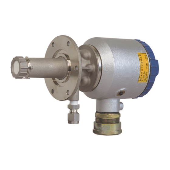
The direct insertion type zirconia oxygen analyzer detector
Hide thumbs
Also See for ZFK8:
- Instruction manual (36 pages) ,
- Instruction manual (35 pages) ,
- Instruction manual (35 pages)

Subscribe to Our Youtube Channel
Related Manuals for Fuji Electric ZFK8


Summary of Contents for Fuji Electric ZFK8
- Page 1 Instruction Manual THE DIRECT INSERTION TYPE ZIRCONIA OXYGEN ANALYZER DETECTOR TYPE: ZFK8 INZ-TN5ZFK8d-E...
- Page 2 PREFACE Thank you very much for your kind purchase of Fuji’s zirconia oxygen analyzer detector (Type ZFK 8). • Read this instruction manual carefully to get a thorough understanding of how this zirconia oxygen analyzer works prior to installing, operating and maintaining the zirconia oxygen analyzer. If abused, unnecessary troubles or failure could occur. • The specification of this zircoia oxygen analyzer may be subject to change without previous notice for im- provements of the product. • Under no circumstances should this zirconia oxygen analyzer be modified without permission. If any trouble should occur because of having been modified without permission, we won’t be responsible for it anyway. • This instruction manual should be kept in custody by a person who operates the zirconia oxygen analyzer actually. • After reading this manual, it should always be kept in a place which allows the person who operates it to refer to any time as requirfed. • A due consideration should be given so that this instruction manual is delivered to a final user certainly.
-
Page 3: Safety Precautions
SAFETY PRECAUTIONS Prior to operating this detector, read this “Safety precautions” carefully for correct use. • In the precautions shown here, important contents on safety are included. So, be sure to observe them. The safety precautions have been ranked into “DANGER”, “CAUTION” and “PROHIBITION”. DANGER If this apparatus is abused, a dangerous condition could come about and it is sup- posed to die or get a serious injury. If the apparatus is abused, a dangerous condition could arise and it is supposed to get CAUTION medium injury or a minor injury and a physical damage is supposed to occur. PROHIBITION This indicates a prohibition (act which must not do). - Page 4 Precautions in operation, stop, maintenance and check • In case where combustible gas is contained in the measured gas, check the gas DANGER composition and specifications carefully before using. Otherwise, the original performance is not displayed, and there is a fear of explosion. • Do the work in a condition where the main power has been turned off. If the CAUTION work is done while current is flowing, there is a fear of getting an electric shock. • The operating temperature of the detector (tip of ceramic heater) is about 800°C and the surface temperature is also very high. So, never touch the detector by bare hand. Otherwise, there is a fear of getting a burn. • Before cleaninhg the flow guide tube, turn off the main power and cool the tube down fully. There is a fear of getting a burn. • Don’t use any other renewal part than those designated by the maker. Other- wise, the original performance is not fully displayed and a accident or failure may result. • Dispose of the renewal parts such as the maintenance parts as an incombustible. • Never do the work at a place where rain water splases the product directly.
-
Page 5: Table Of Contents
CONTENTS PREFACE ............................i SAFETY PRECAUTIONS ......................ii 1. Introduction ..........................1 1.1 General description of zirconia oxygen analyzer ................1 1.2 Device configuration of direct insertion type oxygen analyzer ...........1 1.3 Description of each component ....................2 1.4 Check of type ..........................2 1.5 Check of delivered articles ......................2 2. Mounting ..........................3 2.1 Mounting location ........................3 2.2 Mounting method ........................3 3. Piping ............................7 3.1 Piping of calibration gas ......................7 3.2... -
Page 6: Introduction
: Faraday constant 9.649×10 [c・mol Platinum Oxygen molecule 1.2 Device configuration of direct insertion type oxygen analyzer The direct insertion type zirconia oxygen analyzer consists of the detector with a sensor unit, the flow guide tube that is directly inserted to the stack or the like in order to supply a gas to the detector, and the converter that performs sensor control, signal processing, output/display, and external transmission. The detector and converter are connected with a cable. Stack Detector Converter Flow guide tube Cable Flow of gas (sensor output line, thermocouple output line, heater power wire) Replacement of the existing detector ZFK2 with the detector ZFK8: In principle, the detector ZFK8 is compatible with the existing detectors ZFK2 and ZFK5 structurally and electrically. However, the M4 screws for the terminal block of the detector were changed to the M3 screws. If using the existing cable, change the M4 terminal for cable end treatment on the detector side to the M3 terminal. The detectors ZFK8, ZFK2 and ZFK5 can be connected to the converters ZRY, ZRM or ZKM. The flow guide tube can be connected to the existing products. -
Page 7: Description Of Each Component
description of each component CAUTION • The operating temperature of detector (tip of ceramic heater) is about 800°C and the surface temper- ature is also very high. So, never touch it by bare hand. Otherwise, there is a fear of getting a burn. Especially when a ceramic filter at the end of the detector is replaced, take utmost care. (1) ZFK2 Furnace environment Air environment (Gas to be measured) (Reference gas) O-ring Thermo sticker Ceramic filter Terminal box Filter frame Measured gas Terminal box lid Quartz filter Heat insulating material Hexagon plug or reference gas inlet Ceramic heater * According to designation of type... -
Page 8: Mounting
MOUNTING Mounting location DANGER • This product has no explosion-proof specification. Don’t use the product in an explosive gas environment. If used, a serious trouble such as a fire or explosion might occur. CAUTION • Install this product at a place compatible with the following conditions. The use of it at a place not conforming the installation conditions specified in this manual could cause an electric shock, a fire or incorrect operation. Mount the detector by selecting the places shwon below: 1 Place where there is a space which allows doing daily check and wiring work 2 Place where there is little vibration, dust and humidity 3 Place where peripheral air environment is non-corrosive. 4 Place where there are no electric appliances producing noise trouble (For example : motor, transformer and appliances bringing about electromagnetic induction trouble and electrostatic induction trouble) nearby the detector. 5 Place where ambient temperatue and humidity are -10 to +60°C and less than 95%RH . Mounting method CAUTION •... - Page 9 2.2.1 Mounting method of detector Caution in mounting • Never mount the detector with the tip turned upward or downward. A failure of the detector may result. Down Detector Down Down Mounting screw, plain washer, thermo sticker spring washer (accessory) - 3 locations Flow guide tube or ejector (ZTA) +45° -45° O-ring (accessory) Detector Gas flow Detector flange Wiring hole 1 Attach the O-ring (accessory, Viton P36) to the groove of the detector. Subsequently, attach the detec-...
- Page 10 2.2.2 Mounting method of flow guide tube (Designation of type: When 9th to 11th digits are 5A , 5B and 5C The flange of flow tube has mounting holes at 8 locations. These holes are available for regulating an in- flow into the flow guide and mounting the tube correctly in the flowing direction of gas and it is enough if mounted at 4 locations. (1) Direction of tongue and Partition plate of flow guide tube 1 When exhaust gas temperature is under 200°C and gas flowing velocity is low As illustrated below, set the partition plate inside the flow guide tube at a right angle to the gas flow and mount the tube so that the tongue turns to an upstream direction relative to the gas flow. Packing (not included Furnace wall in scope of supply) Partition plate Tongue Arrow mark of flow guide tube Gas flow min.60mm...
- Page 11 2.2.3 Mounting method of high dust-use flow guide tube (Desingation of type : When 9th to 11th digits are 6D and 6E) Mount the tube so that the gas outlet turns downward relative to the gas flow as shown below. Fitted with high dust cover For high dust Gas outlet Gas outlet Gas flow Gas flow Gas flow Gas flow Inserting angle Be careful not to block the gas outlet by the furnace wall or pipe and keep the periphery of the outlet widely. Set the inserting angle within a range of 0 to +45°.
-
Page 12: Piping
PIPING 3.1 Piping of calibration gas Main body As the piping material, use a teflon-made ø6mm or ø1/4inch tube. (calibration gas inlet) • From the coupling attached to the detector, remove (2) nut, (3) front ferrule and (4) back ferrule, put them through to the (1) Coupling ø6mm or ø1/4inch teflon tube for piping, and then attach it to (1) coupling. • For mounting (2) nut, tighten by making about 2 turns with a spanner after it cannot be turned any more by hand. (3) Frount ferrule Joint for calibration gas: (4) Back ferrule The joint for calibration gas is a special joint with a built-in check valve. If a malfunction occurs, order the joint for calibration gas and attach it. -
Page 13: Piping Drawing
φ10/φ8 PTFE or φ10/φ8 PTFE pipe or copper pipe pipe or copper pipe Flow guide tube (not supplied) (not supplied) Detector (ZFK8) AC power supply Gas temperature. 600ºC max. Rainproof flexible White Ref. air conduit. Black (Max. - Page 14 φ10/φ8 PTFE or φ10/φ8 PTFE pipe or copper pipe pipe or copper pipe Flow guide tube (not supplied) (not supplied) Detector (ZFK8) AC power supply Gas temperature. 600ºC max. Rainproof flexible White conduit. Ref. air Black (Max.
- Page 15 Gas temperature. (not supplied) 1500ºC max. Heater temperature drop Alarm Solenoid valve Copper pipe Copper pipe φ10/φ6mm (not supplied) φ10/φ8mm (not supplied) (not supplied) Detector (ZFK8) AC power supply White Rainproof flexible Black conduit. White (Max. 20m) Yellow Bule TM-1 +...
- Page 16 Gas temperature. (not supplied) 1500ºC max. Heater temperature drop Alarm Solenoid valve Copper pipe Copper pipe φ10/φ6mm (not supplied) φ10/φ8mm (not supplied) (not supplied) Detector (ZFK8) AC power supply White Rainproof flexible Black conduit. White (Max. 20m) Yellow Bule TM-1 +...
-
Page 17: Wiring
WIRING CAUTION • In the case of the wiring work, be careful not to drop foreign matters including wire chips inside the product. Otherwise, this might cause a fire, failure or malfunction. • Connect a power source compatible with the rating. Connection of a power source not conforming to the rating may cause a fire. • Before proceeding with the wiring work, be sure to turn off the main power supply. Otherwise, there is a fear of getting an electric shock. • As the wiring material, use a proper one conforming to the rating of apparatus. The use of a wiring material which is not bearable to the rating could cause a fire. PROHIBITION • Under no circumstances be the work at a place where the product gets wet with water, such as the rain. Otherwise, an electric shock or failure may result. -
Page 18: Before Wiring
Before wiring Put a cable (6 cores in all) connected between detector and converter into a piping tube for protecting the cable. Also, put the cables for R thermocouple and element output away from the power cable to take a noise preventive step. When an exclusive cable is not used, use the following wire rods: • For heater (2 pcs.) ....3A or more in rating • For R thermocouple ....Specified in JIS C1610-1995 (equivalent to RCA-2-G-0.75mm • Recommended wire rod (at 20 ºC) Element output For heater compensation conductor Nominal sectional area (mm2) 0.75 Number of composed element wires/ 30/0.18 diameter of element wire (mm) Outside dia. (mm) 1.14 Thickness of vinyl insulating material (mm) Thickness of vinyl sheath (mm) Max. -
Page 19: Mounting Of Conduit
Connect the protective grounding to one of the two terminals in the figure below. (Class D (Class 3) grounding, grounding resistance: 100Ω or less) Note • Use the cable more than 0.75mm for main ground (earth) line. • For solderless terminal , doubly caulk the core and the sheath Grounding terminal separately. The core should be poked from 0.5 to 1.0 mm. The core should be so as not to be seen or not to be come apart. -
Page 20: Operation And Stop
OPERATION ANd STOP DANGER • In case where combustible gas is contained in the measured gas, make sure of the gas composition and specifications carefully before using this product. Otherwise, the original performance is not displayed and there is a fear of explosion. Start of operation • If the power switch of the converter is turned on after completion of wiring and piping work, the detector starts its operation. • After warm-up at least 10 minutes, start the operation of the furnace. • After zero calibration and span calibration have finished, get to work on the measurement. • For the method of calibration, refer to each instruction manual of converters (ZKM, ZRM and ZRY). • When the converters (ZKM, ZRM and ZRY) are not used, run the zero and span calibration gases and calibrate by converting the output in a stabilized state into oxygen concentration according to the standard output table of converter in Item. “6.3”. -
Page 21: Maintenance And Check
MAINTENANCE ANd CHECk CAUTION • Do the work in a condition where the main power supply has been turned off. If the work is done while current is flowing, there is a fear of getting an electric shock. • The operation temperature of the detector (tip of the ceramic heater) is about 800°C and the surface temperature is also very high. So, never touch it by bare hand. Otherwise, there is a fear of getting a burn. • Before proceeding with the cleaning of the flow guide tube, turn off the main power and cool the tube down fully and then, do the work. Otherwise, there is a fear of getting a burn. • Don’t use other renewal parts than those designated by the maker. Otherwise, the original performance is not displayed fully and an accident or failure could come about. • Dispose of the renewal parts including the maintenance parts as an incombustible. PROHIBITION • Under no circumstances the work at a place where the product gets wet with water, such as the rain. Otherwise, an electric shock or failure may result. Check Perform the check periodically for using the product always in good condition. Especially, perform the checks shown in table below. Moreover, perform the periodic check at a time of checking the furnace or every 6 months. Check items Details of checking work Execution of zero & span calibration... -
Page 22: Maintenance
Maintenance The replacing intervals of sensor unit, ceramic filter and O-ring, and the maintenance periods of flow guide tube and sampling probe differ depending on the working conditions including the components of measured gas and the amount of dust. The replacing intervals in a general conditions are shown below. Determine the replacing intervals in the individual working condition with a period till a first replacement after delivery and operation as a rough standard. • Sensor unit ..........Yearly • Ceramic filter ..........At 6 month interval • Flow guide tube ........At 3 to 4 year interval • ZTA sampling probe ......... At 3 to 4 year interval • O-ring ............Yearly 6.2.1 Replacement of Sensor unit Caution about the replacement of the sensor unit: • Check that the sensor unit complies with the specifications of the power supply you use. •... - Page 23 6.2.2 Replacement of ceramic filter (1) After turning “OFF” the power of the detector, lower the surface Reflector temperature of the tip (at the ceramic filter side) by cooling down fully with the air. (2) After having been cooled down fully, remove the filter frame from the detector, take the ceramic filter and reflector off the filter frame. (3) Set a new ceramic filter and reflector in the filter frame and fit the frame to the detector and then, tighten till the ceramic filter does Ceramic filter not move any longer. (Be careful then not to fail to set the reflec- Filter frame tor in place. For the part No. for additional procurement of the reflector, refer to Item. “6.4”). 6.2.3 Maintenance of flow guide tube • After removing the flow guide tube from the furnace wall and then, from the detector, cool the tube down fully in the air. • Remove dust sticking to the outside of the flow guide tube by water-washing with the use of a scrubbing brush. • Remove dust sticking to the inside of the flow guide tube by using a metallic rod or screwdriver. (Clean so that tube is through at least about 3/4 part of the whole interior.) • For the flow guide tube for high dust, remove together dust sticking around the gas outlet. 6.2.4 Maintenance of sampling probe • After removing the ejector (ZTA) from the furnace wall and then, the sampling probe from the ejector, cool the probe down fully in the air.
-
Page 24: Standard Output Of Detector
Standard output of detector For the output voltage of the detector, refer to the standard output table below. Standard output table (Reference) Oxygen Detector output Oxygen Detector output Oxygen Detector output concentration (Unit: mV) concentration (Unit: mV) concentration (Unit: mV) (Vol%) (Vol%) (Vol%) 0.01 168.15 3.5 39.06 14.0 8.51 0.05 132.68 4.0 36.12 15.0 6.99 0.1 117.41 4.5 33.52 16.0 5.57 0.5... -
Page 25: Arrangement
Arrangement No. Description Classification Part No. for procurement Remark (Procured type) 1 Ceramic filter Consumable *ZZPZFK5-TK750201P1 2 Detector O-ring (P38) Consumable *ZZPZFK5-8552836 Viton 3 Sensor unit for replacement Spare parts According to designation of type in screw with washer (M3×8): Item. “8.2” 4 pcs. O-ring (S22.4, Viton) : 1 pc. 4 Flow guide tube Spare parts According to part No. for procurement of flow guide shown in table below 5 Calibration gas inlet Additionally *ZZPZFK5-TK7N6820C1 (for φ 6mm tube) procurement part Calibration gas inlet Additionally... -
Page 26: Troubleshooting
TROUBLESHOOTING CAUTION • If a failure should occur which cannot be judged even if referring to the operation manual, be sure to ask the nearest dealer or Fuji adjustment serviceman for repair. If disassembled carelessly, there is a fare of an accident or injury. Troubles Probable causes Check procedures (normal values) Remedies • Indication is fixed. • Clogging of ceramic filter • Check visually for fouling of ce- • Clean or exchange ce- of detector and flow guide ramic filter of detector and clog- ramic filter, if need be. • Indication response tube interior ging of flow guide tube interior is slow. with dust. • Leak from joint and airtight- • Check for looseness of each joint • Retighten and replace ness of mounted part. -
Page 27: Appendix
APPENdIx 8.1 Specification Operating temperature: General Specifications −10 to +60ºC for Primary detecting ele- Measuring object: Oxygen in noncombustible gas ment Measuring method: −5 to +100ºC for ejector section Directly insert type zirconia system 125ºC or less at detector flange surface Measuring range: 0 to 2 ···... - Page 28 Converter specification (ZKM) Output signal hold: Output signal is held during calibration, Concentration value indication: processing recoverable sensor, process- Digital indication in 4 digits ing diagnosis of sensor, warm-up, PID Contact output signal: auto tuning, under set up maintenance (1) Contact specification; 6 points, 1a 250V AC/3A or 30V DC/3A mode "available"...
-
Page 29: Designation Of Type (Code Table)
8.2 Designation of type (code table) 8.2.1 detector 8.2.2 Replacement sensor unit 4 5 6 7 8 9 10 11 12 13 14 15 16 Power supply Code symbols Description 100 to 120V AC ZFK8YY15-0Y0YY-0YY Cal. gas inlet For ø6mm tube (SUS) 200 to 240V AC ZFK8YY35-0Y0YY-0YY For ø1/4 inch tube (SUS) Ball valve... -
Page 30: Device Composition
8.2.4 Converter (2) Exclusive cable for converter (1) ZKM 3 4 5 6 7 8 3 4 5 6 7 8 9 10 11 12 Description Description Connectable devices Construction IP66 For ZKM IP67 Types Bench type For R thermocouple Output signal Conduit length Cable length 4 to 20mA DC None 0 to 1V DC... -
Page 31: Outline Diagram (Unit: Mm)
8.4 Outline diagram (unit: mm) (1) Detector (ZFK8) Approx.132 ø80 Approx.62 Approx.130 ø67 Heat insulating cover (as specified) 6-ø6 Terminal box EXTERNAL CONNECTION DIAGRAM Heater Thermocouple Element output Filter Black / White/ red / White/ yellow / blue 2-core wire 4-core wire Ground-wire Exclusive cable... - Page 32 ( 4 ) Flow guide tube (For corrosive gas) ø155 Approx. 40 Approx. L ø130 ø67 Gas inlet Z F K 8 R 5 - 5 B 3 6-M5 Gas outlet detector side Code 11th 0.5 0.75 1.0 L (m) MASS (as specified) Approx.(kg) 8-ø15 Oxygen detector MTG.
- Page 33 (6) Flow guide tube (for high particulate) 4-Rc1/4 with plug Blow down air inlet When mounting, select one of blow inlets on the upper side 8 - ø19 (for prevention of drain) MTG. hole Flange: JIS 5K80A FF ZFK MTG. position Packing Z F K 8 R 5 - 6 D Elongate hole...
- Page 34 (7) Flow guide tube (for high particulate with cover) 4-Rc1/4 with plug Blow down air inlet When mounting, select one of blow inlets on the upper side 8 - ø19 MTG. holes (for prevention of drain) Flange: JIS 5K80A FF ZFK MTG. position Packing Elongate Z F K 8 R 5 - 6 E hole Gas outlet...
- Page 35 Instrumentation & Sensors Planning Dept. 1, Fuji-machi, Hino-city, Tokyo 191-8502, Japan http://www.fujielectric.com Phone: +81-42-514-8930 Fax: +81-42-583-8275 http://www.fujielectric.com/products/instruments/...
Need help?
Do you have a question about the ZFK8 and is the answer not in the manual?
Questions and answers