Table of Contents
Advertisement
Quick Links
Advertisement
Table of Contents

Subscribe to Our Youtube Channel
Related Manuals for Fuji Electric ZPB


Summary of Contents for Fuji Electric ZPB
- Page 1 Instruction Manual NDIR TYPE INFRARED GAS ANALYZAR TYPE: ZPB INZ-TN2ZPB-E...
- Page 2 PREFACE Thank you very much for purchasing Fuji’s Infrared Gas Analyzer (Type: ZPB). injury. Request INZ-TN2ZPB-E...
-
Page 3: Caution On Safety
CAUTION ON SAFETY To operate the analyzer properly, be sure to read “Caution on Safety” carefully. DANGER CAUTION damage. PROHIBITION CAUTION Caution on installation and transport of gas analyzer DANGER CAUTION INZ-TN2ZPB-E... - Page 4 Caution on piping Be sure to observe the following precautions while installing DANGER piping. Improper piping may result in gas leakage. If the leaking gas contains a toxic component, serious acci- dents may result. If it contains combustible gases, explosion Caution on wiring CAUTION Caution on use...
- Page 5 Caution on use PROHIBITION Caution on maintenance and check DANGER Be sure to observe the following to perform work safely, CAUTION avoiding electric shock or injury. Others CAUTION INZ-TN2ZPB-E...
-
Page 6: Warranty And Maintenance
WARRANTY AND MAINTENANCE Scope of application Operating conditions and environment Precautions and prohibitions Warranty 4-1. Period of warranty 4-2. Scope of warranty from: INZ-TN2ZPB-E... -
Page 7: Failure Diagnosis
Failure diagnosis Service life Maintenance plan Maintenance Preventive Daily inspection maintenance Periodic inspection Corrective Troubleshooting maintenance INZ-TN2ZPB-E... - Page 8 Limited-life parts and consumable parts Spare parts and accessories accessories. 10. Period for repair and provision of spare parts after product dis- continuation (maintenance period) INZ-TN2ZPB-E...
- Page 9 CONTENTS ........................i ....................ii ............... v ......................viii ................................................................................ 4 .................... 4 ......................5 ............... 5 ........................6 ............................................................................................................................................................................................................................................................................................................................
- Page 10 ............................................................................................................................................................................................................................................................................44 ................... 44 ............46 ......................................... 54 ................................................................64 ....................65 ......................65 ............65 ..................66 ..........................................
- Page 11 1. OVERVIEW INZ-TN2ZPB-E...
-
Page 12: Name Of Delivered Items And Each Parts
2. NAME OF DELIVERED ITEMS AND EACH PARTS Analyzer: 1 unit Standard: IEC127-2 Size: ø5 × 20mm Fuse: 2 pcs Rating: 250V/2A delay type Part No.: R75796N17 25 pin D-sub connector (male) Analog output connector: 1 Part No.: R77256N262 Fixing screws: 2 M2.6 ×... -
Page 13: Name And Description Of Analyzer
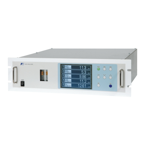
2.2 Name and description of analyzer (3) Flowmeter (unit mm) < Front panel > (2) Display/operation panel (1) Power switch (12) Analog output connector (A / O) (D-sub25 pin) (4) Purge gas inlet (11) Communication connector (RS-485) (5) Sampling gas inlet (6) Sampling gas and (10) External input connector reference gas outlet... -
Page 14: Installation Conditions
3. INSTALLATION DANGER CAUTION injury. 3.1 Installation conditions unit : mm analyzer (installed) analyzer (drawer out) INZ-TN2ZPB-E... -
Page 15: Installation Of Analyzer Main Frame
3.2 Installation 3.2.1 Installation of analyzer main frame (Unit : mm) Type External dimensions Mounting dimensions Mounting method 19-inch rack mounting 450 or more Support “A” : 57.2 (EIA) INZ-TN2ZPB-E... - Page 16 3.3 Piping CAUTION coupling. Purge gas inlet Sampling gas inlet 1 Reference gas inlet Sampling gas and reference gas outlet 1 Sampling gas inlet 2 For special case only Sampling gas outlet 2 INZ-TN2ZPB-E...
- Page 17 Internal piping diagram Optical unit 2 (IR Unit 2) Optical unit 1 (IR Unit 1) (Left) (Right) Built-in sensor Sampling cell REFERENCE INLET1 OUTLET1 Note) 2 cells may be used Sampling gas inlet Sample gas outlet/ by combination of Reference gas outlet range.
-
Page 18: Preparation Of Standard Gas
3.4 Sampling 3.4.1 Conditions of sampe gas consider- 3.4.3 Preparation of standard gas mea- sensor sensor Zero gas Dry air mea- 3.4.4 Purging of instrument inside INZ-TN2ZPB-E... -
Page 19: Pressure At Sampling Gas Outlet
3.4.5 Pressure at sampling gas outlet (1) Gas extractor ZPB unit (7) Membrane filter (8) Flowmeter ø10/ø8 (4) Gas aspirator Teflon Air filter tube analyzer (11) NO /NO converter (Wet N2 or main frame (for NO measurement) 3-way atmospheric air) - Page 20 3.4.7 Gas requirements for measurement and calibration From reference From sample gas Remarks gas inlet inlet Zero calibration Dry N or dry air Dry N or dry air Use dry gas (cylinder) for Calibration both zero and span cali- Span calibration Dry N or dry air Dry span gas...
- Page 21 3.5 Wiring CAUTION CAUTION External input connector (A/I) Communication connector (RS-485) Analog output connector (A/O) Power terminal block Digital input/output connector Power inlet (DIO 1 to 3) INZ-TN2ZPB-E...
-
Page 22: Power Supply
(1) Power supply <Terminal block for power supply> <Power inlet> 3 2 1 Attached ferrite core Power inlet AC100 to 240V Earth cable Grounding 2-pole plug CAUTION When noise source is in the vicinity Main unit power supply Varistor or spark quencher Install (connect) near the source. - Page 23 (2) Analog output signal: Analog output connector (A/O) < Analog output > A/O connector AO1+ AO1- AO2+ AO2- AO3+ D-sub 25-pin female AO3- AO4+ Note) Display Ch number is same AO4- as the AO number under AO5+ AO5- standard specifications. AO6+ AO6- AO7+...
- Page 24 (3) O sensor input: External input connector (A/I) or more) < External input > A/I connector (O sensor input) ordered. full scale analyzer is Turn To O sensor − Solder the signal cable to the terminal. INZ-TN2ZPB-E...
- Page 25 (4) Contact input/output (DIO): digital input/output connector (DIO1 to 3) < Digital input/output > Connector for DIO 1 to 3 (option) DIO1 DIO2 DIO3 connector connector connector DI1+ DI4+ DI7+ DI1- DI4- DI7- Digital input DI2+ DI5+ DI8+ OFF : 0V DI2- DI5- DI8-...
- Page 26 (5) Communication: RS-485 connector < RS-485 connector > (GND) RT D+ RT D- D-sub 9-pin female 3.6 Timing of contact output for calibration 1) Manual calibration (See “Section 6.8 Calibration”.) INZ-TN2ZPB-E...
- Page 27 2) In case of automatic calibration (example shown in Section 6.4.1, Auto calibration) Automatic Ch1 span Ch3 span calibration Ch5 span calibration calibration start calibration Ch4 span Ch2 span Zero calibration calibration calibration Zero gas Zero calibration output 350 s Ch1 span calibration output Ch1 span gas 350 s...
-
Page 28: Preparation For Operation
4. OPERATION 4.1 Preparation for operation (1) Piping and wiring check 4.2 Warm-up operation and regular operation (1) Operation procedure CAUTION When in warm-up, the concentration reading may be beyond the upper limit of range. But, it is not an error. INZ-TN2ZPB-E... -
Page 29: Description Of Display And Operation Panels
5. DESCRIPTION OF DISPLAY AND OPERATION PANELS 5.1 Name and description of operation panel Display unit Operation panel (7) ZERO key (8) SPAN key MODE ZERO SPAN (1) MODE key (4) DOWN key (2) SIDE key (3) UP key (5) ESC key Name Description Name... -
Page 30: Overview Of Display And Operation Panels
5.2 Overview of display and operation panels INZ-TN2ZPB-E... -
Page 31: Outline Of Display Screen
5.3 Outline of display screen (1) Measurement mode screen (appears when the power is turned ON) 0-50 0-50 0-50 0-50 0.0 0 Scroll vol% 0-20 0-50 0-50 0-50 0.0 0 vol% vol% 0-25 vol% 0-25 INZ-TN2ZPB-E... - Page 32 Instantaneous value and concentration value: corrected concentration values: × corrected concentration average value: aver- (2) Setting/selection screen Message display area Status display area display area Cursor INZ-TN2ZPB-E...
- Page 33 (3) Contents of measured channel (Ch) Code symbol 6th digit 7th digit 21st digit Display/output contents Ch1:NO Ch1:SO Ch1:CO Ch1:CO Ch1:NO, Ch2:SO Ch1:NO, Ch2:CO Ch1:CO , Ch2:CO Ch1:NO, Ch2:SO , Ch3:CO Ch1:NO, Ch2:SO , Ch3:CO , Ch4:CO 1 to 4 Ch1:NO, Ch2:O 1 to 4 Ch1:SO...
-
Page 34: Basic Operation
5.4 Basic operation 0 0 . 0-50 0 0 . 0-50 0 0 0 0-20 vol% one. 0 0 . 0-50 0 0 0 0-25 vol% ZERO 0 0 0 0-25 vol% 0 0 . Zero calibration 0-50 See 6.8.1. . -
Page 35: Setting And Calibration
6. SETTING AND CALIBRATION 6.1 Switch of range Measurement Mode Screen 6.1.1 Setting of range switch mode MODE MODE User Mode Select an item with UP/DOWN and ENT Back with ESC Switch Ranges Calibration Parameters key. Alarm Setting Setting of Auto Calibration Setting of Auto Zero Calibration Peak Alarm Setting Parameter Setting... -
Page 36: Manual Range Switch
6.1.2 Manual range switch Switch Ranges Select Ch No. Switch ranges with UP/DOWN and ENT Back with ESC key. Range1 0–50.00 Range2 0–500.0 Range1 0–50.00 Range2 0–500.0 Range1 0–10.00 vol% Range2 0–20.00 vol% Range1 0–50.00 Range2 0–500.0 Range1 0–10.00 vol% Range2 0–25.00 vol%... -
Page 37: Setting Of Calibration Concentration
6.2 Calibration setting Cal. Parameters Select an item with UP/DOWN and ENT Back with ESC Calibration Value 6.2.1 Setting of calibration concentration About ZERO Calibration About Calibration Range About Calibration Components / Range Cal. Settings Select setting value Cal. Value RANGE ZERO SPAN... - Page 38 Cursor for setting value value increases or decreases. By pressing Cal. Settings Set calibration value Cal. Value RANGE ZERO SPAN 0–50.00ppm +0000.0 50.00 0–500.0ppm +00000 500.0 0–50.00ppm +0000.0 50.00 Note) Enter settings that correspond to 0–500.0ppm +00000 500.0 each range. If zirconia type is used 0–10.00ppm +000.00 10.00...
-
Page 39: Setting Of Manual Zero Calibration
6.2.2 Setting of manual zero calibration Cell. Settings Set each or at once Ch ZERO Call. at ZERO Calibration Range1 0–50.00 at once Range2 0–500.0 Range1 0–50.00 at once Range2 0–500.0 Range1 0–10.00 vol% at once Range2 0–20.00 vol% Range1 0–50.00 at once Range2... - Page 40 Manual Calibration screen When setting all components to “each”: When setting all components to “at once”: ZERO Call. ENT : Go on Calibration ZERO Call. ENT : Go on Calibration of selected Ch of selected Ch ESC : Not calibration ESC : Not calibration -2.1 Range1...
-
Page 41: Setting Of Calibration Range
6.2.3 Setting of calibration range Cell. Settings Set calibration range Cell. Range current or both range Range1 0–50.00 both Range2 0–500.0 Range1 0–50.00 current Range2 0–500.0 Range1 0–10.00 vol% current Range2 0–20.00 vol% Range1 0–50.00 both Range2 0–500.0 key. Range1 0–10.00 vol% current... -
Page 42: Setting Of Auto Calibration Component/Range
6.2.4 Setting of auto calibration component/range Cell. Settings Select a range for Auto Cal. auto calibration Range1 0–50.00 enable Range2 0–500.0 Range1 0–50.00 enable Range2 0–500.0 Range1 0–10.00 vol% enable Range2 0–20.00 vol% Range1 0–50.00 enable Range2 0–500.0 Range1 0–10.00 vol% enable Range2... - Page 43 To close the setting Press the key to exit automatic calibration component/range setting, and the previous screen appears. Operation by setting Auto calibration is performed under the following rules. 1. Zero calibration is performed at the same time, for the Ch (component) in which “enable” is selected at the time of auto calibration and auto zero calibration.
-
Page 44: Setting Of Alarm Values
6.3 Alarm setting 6.3.1 Setting of alarm values Alarm Setting Select Alarm No. or Hysteresis setting Alarm-1 key. Press Alarm-2 key. Alarm-3 Alarm-4 Alarm-5 Hysteresis Alarm Setting Select an item with UP/DOWN and ENT Alarm-1 Back with ESC key. Channel CAUTION H-Limit Range 1 50.00... - Page 45 Description of setting items The alarm contact assigned the same number as the alarm is operated accordingly. Channel: Channel setting targeted for issuance of alarm. One Ch No. can be selected for multiple alarms. H-Limit value: Sets the high limit value (concentration) of alarm. L-Limit value: Sets the low limit value (concentration) of alarm.
-
Page 46: Hysteresis Setting
6.3.2 Hysteresis setting esis. Alarm Setting Set Hysteresis 0 to 20%FS available Alarm-1 Alarm-2 Alarm-3 Alarm-4 Alarm-5 Hysteresis End of Hysteresis Setting To close "Hysteresis Setting" To close the “Hysteresis Setting” or cancel the mode midway, press the key. A previous screen will return. CAUTION Setting range The hysteresis is common to all alarms... -
Page 47: Peak Alarm Setting
6.3.3 Peak alarm setting Measurement Mode Screen MODE MODE User Mode Select an item with UP/DOWN and ENT key. Back with ESC key. Switch Ranges Calibration Parameters Alarm Setting Setting of Auto Calibration key. Setting of Auto Zero Calibration Peak Alarm Setting Parameter Setting Peak Alarm Select setting item... - Page 48 Setting range Alarm value : 10 to 1000 ppm 5 ppm step (initial value: 500 ppm) Alarm count : 1 to 99 times (per hour) (initial value: 5 times) Hysteresis : 0 to 20 % of full scale (initial value: 0% of full scale) [% full scale] represents the percentage with the CO range regarded as 100%.
-
Page 49: Setting Of Auto Calibration
6.4 Setting of auto calibration 6.4.1 Auto calibration Set Auto Cal. Select setting item Start Time 12:00 Cycle key. Flow Time ON / OFF Time : MON 12:34 Auto Calibration Run Set Auto Cal. Set Start Time Start Time 12:00 Press the Cycle key, and... - Page 50 Set Auto Cal. Set flow time of calibration gas 60 to 900 sec ZERO 350 sec. Ch1 Span 350 sec. key. Ch2 Span 350 sec. Ch3 Span 350 sec. Ch4 Span 300 sec. Ch5 Span 300 sec. Ex. time 300 sec. key.
-
Page 51: Remote Start
cases. Example 12:00 Start Time Cycle 350 sec Flow Time Zero 350 sec Ch1 Span 350 sec Ch2 Span 350 sec Ch3 Span 300 sec Ch4 Span 300 sec Ch5 Span 300 sec EX. time ON/OFF In case where auto calibration is carried out at the above setting. Sunday Monday Tuesday... -
Page 52: Forced Run/Stop Of Auto Calibration
6.4.2 Forced run/stop of auto calibration 6.4.2.1 Execution of auto calibration (only once) Set Auto Cal. Auto Cal. Run ENT : Run / Stop ESC : Cancel key. Start Time 12:00 Cycle Flow Time ON / OFF Time : MON 12:34 Auto Calibration 6.4.2.2 Forced stop of auto calibration Set Auto Cal. - Page 53 “Auto Calibration” screen Example 0 3 . 0 0 0 0 0 0 . 2 1 0 2 9 0 8 0 0 . 0 0 0 0 0 . 0 0 0 9 5 0 . 0 0 0 0 0 .
-
Page 54: Setting Of Auto Zero Calibration
6.5 Setting of auto zero calibration 6.5.1 Auto zero calibration Set Auto Select setting item Zero Cal. Start Time 12:00 Cycle key. Flow Time sec. ON / OFF Time : MON 12:34 Auto Zero Calibration Run Set Auto Set Start Time Zero Cal. - Page 55 Example Start time 12:00 Cycle hour Flow time ON/OFF In case where auto zero calibration is carried out at the above setting. Sunday Monday Monday 12:00 0:00 12:00 Cycle : Auto zero calibration Replace- Zero ment calibration time 300sec 300sec Gas replacement time after calibration is the same as the flow time.
-
Page 56: Forced Run/Stop Of Auto Zero Calibration
6.5.2 Forced run/stop of auto zero calibration 6.5.2.1 Execution of auto zero calibration (only once) Set Auto Auto zero Run ENT : Run / Stop Zero Cal. ESC : Cansel key. key. Start Time 12:00 Cycle Flow Time sec. ON / OFF Time : MON 12:34 cancel. - Page 57 “Auto Zero Calibration” screen Example 0 3 . 0 0 0 0 0 . 2 1 0 2 CAUTION During auto zero calibration, any key operation is not permitted other than operations such as key lock ON/OFF and “Forced stop of auto zero calibration”. When the key lock is set at ON, even the “Forced stop of auto zero calibration”...
-
Page 58: Parameter Setting
6.6 Parameter setting Description of setting items Parameter Select setting item Current Time 12/01/11 WED 13:50 key. Key Lock Output Hold Current Response Time Average Period Backlight Timer 05 min Contrast To Maintenance Mode 0000 Parameter Set day of week Current Time 12/01/11 13:50... - Page 59 Setting Range Output Hold Manual calibration ZERO Press the key to flow gas. SPAN To execute calibration, press the key. Calibration Hold extending time Output hold Time set to gas flow time (See Section 6.4) b. Auto calibration Auto calibration start Span calibration end Calibration Hold extending time.
- Page 60 Parameter Select Hold ON or OFF Current Time 12/01/11 WED 13:50 Key Lock Output Hold Current Response Time Average Period Backlight Timer 05 min Contrast To Maintenance Mode 0000 Parameter Select Hold setting key. Current Time 12/01/11 WED 13:50 Key Lock Output Hold Setting Response Time...
-
Page 61: Response Time
Parameter Set Hold value 0 to 100%FS Hold key. key. Meaning of setting The setting is expressed as 1/1 full scale range for both respective ranges. When 0 to 1000 ppm is selected as the range, and 10% FS is selected as hold setting, the output equivalent to 100 ppm is End of Hold Setting held irrespective of the measure-ment value at... - Page 62 Average period Parameter Select Ch No. average. Average Period hour Ch10 hour Ch11 hour average value. (Press- Ch12 hour Reset AV. Output Reset Average value reset Contact input flow With input (hold at least 1.5 sec.) Without input Reset input So long as with input, resetting lasts.
-
Page 63: Backlight Timer
Backlight Timer Parameter Set Backlight Timer ON or OFF Current Time 12/01/11 WED 13:50 Key Lock Output Hold Setting off. Response Time Average Period Backlight Timer 05 min Contrast To Maintenance Mode 0000 Contrast Parameter key. key. Current Time 12/01/11 WED 13:50 Key Lock Output Hold Setting... -
Page 64: Maintenance Mode
6.7 Maintenance mode Maintenance Select operating item Mode 1. Sensor Input Value 2. Error Log 3. Cal. Log 4. Output Adj. 5. Other Parameter key. 6. To Factory Mode played. Note) “To Factory Mode” is used for our service engineers only. Each “Maintenance”... - Page 65 Description of Calibration Log screen Maintenance Select Ch No. Cal. Log Past calibration history is displayed. Sensor input value, concentration value, and the date when zero/span calibration is performed are logged. The 10 newest calibration data are logged by each component. Move the cursor to Clear Calibration Log and press the key, and the calibration log is...
- Page 66 Description of output adjustment screen Maintenance Adjust OUTPUT Analog output adjustment screen. ZERO and SPAN Mode Connect the digital multi meter to the output Output Adj. terminal corresponding to the number of OUT Zero Span Zero Span to be adjusted, and adjust the value so that 4mA 00600 03700 00600 03700 or 0V is output at zero and 20mA or 1V is...
- Page 67 Description of each setting screen Maintenance Set Password Mode Password Set : Set the password used to move Setting from the parameter setting screen to the maintenance mode. Password Set 2465 Arbitrary 4-digit number can be ref. Value 12% O limit 20% O selected.
- Page 68 Maintenance Select an item Mode setting Password set 2465 ref. Value 12% O limit 20% O Station No. 01 Range setting key. Maintenance Select Ch No. Mode Range set key. Maintenance Select range or Mode range num. Range set key. Ch1 NOx MIN range 50.00...
- Page 69 6.7.1 Sample switch setting Maintenance Select operating item Mode Sample Switch Gas Flow Time Interference Coefficient (meas.) Interference Coefficient (cal.) Maintenance Select operating item Mode Sample Switch Gas Flow Time REF. Gas: Replacement Time REF. Gas: Measuring Time REF. Gas: Flowing Time SMP.
- Page 70 Maintenance Set the gas key. Mode replacement time. Sample Switch 1 to 30 sec Gas Flow Time REF. Gas: Replacement Time REF. Gas: Measuring Time REF. Gas: Flowing Time SMP. Gas: Replacement Time SMP. Gas: Measuring Time SMP. Gas: Flowing Time Maintenance Select operating item Mode...
- Page 71 Maintenance Select operating item Mode Sample Switch Gas Flow Time Interference Coefficient (meas.) Interference Coefficient (cal.) Maintenance Select Ch No. Mode Sample Switch Interference (c) 1.000000 1.000000 1.000000 1.000000 value. rized. INZ-TN2ZPB-E...
- Page 72 6.7.1.3 Explanation of sample switch method Measuring time of Measuring time of Measuring time of Measuring time of reference gas sample gas reference gas sample gas Folw time of Folw time of Folw time of Folw time of reference gas sample gas reference gas sample gas...
-
Page 73: Manual Calibration Procedure
6.8 Manual calibration procedure Measurement Mode Screen 6.8.1 Manual zero calibration ZERO ZERO Cal. Select Ch No. with UP / DOWN and ENT Back with ESC Range 1 0-50.00 ZERO Range 2 0-500.0 Range 1 0-50.00 Range 2 0-500.0 Range 1 0-10.00 vol% 0.00 Range 2 0-20.00... - Page 74 6.8.2 Manual span calibration measure- Measurement Mode Screen SPAN sensor. SPAN Cal. Select Ch No. with UP / DOWN and ENT Back with ESC SPAN Range 1 0-50.00 Range 2 0-500.0 Range 1 0-50.00 Range 2 0-500.0 Range 1 0-10.00 vol% 0.00 Range 2 0-20.00...
-
Page 75: Daily Check And Maintenance Procedures
7. MAINTENANCE 7.1 Daily check (1) Zero calibration and span calibration (2) Flow rate check 7.2 Daily check and maintenance procedures Table 7.1 Maintenance and check table Phenomena sampling cell. repair. purge gas (Purge gas purging). analyzer analyzer Gas analyzer phenomena INZ-TN2ZPB-E... -
Page 76: Long Term Maintenance
7.3 Long term maintenance Gas analyzer annual inspection plan levels in sample and reference gases). Year Recommended Component name Q’ty replacement Delivered 10th period (year) year year year year year year year year year year year Fuel cell O analyzer (build-in) Infrared light source O-ring for sampling cell Detector... -
Page 77: Cleaning Of Sampling Cell
7.4 Cleaning of sampling cell CAUTION Maintenance actions should only be accomplished by properly trained and qualified personel. Not withstanding these maintenance steps, local facility and organizational safety program requrirements must be followed. 7.4.1 Disassembly and assembly of sampling cell a. - Page 78 Name Screw (for fixing the light source unit) Screw (for fixing the detector) Screw (for fixing the gas filter) Base plate Light source unit Screw (for fixing the support) Screw (for fixing the cell retainer) Gas filter Filter Support Cell retainer Pipe cell O-ring Infrared transmission window...
- Page 79 b. How to remove block cell (See Fig. 7-2) Note) The O-ring (No. 9) is placed between the window holder and block cell. Take care about the O-ring position. With 2-component analyzer, install 2-component detector last. Take care so that no space is left between the 1-component and 2-component detectors.
- Page 80 Name Screw (for fixing the light source unit) Filter Screw (for fixing the detector) Base plate Light source unit Screw (for fixing the block cell) Block cell Infrared transmission window (window holder) O-ring Screw (for fixing the measuring unit) Gas filter Detector Light source power PCB INZ-TN2ZPB-E...
- Page 81 c. How to remove measuring unit (See Fig. 7-3) Note) Special care should be taken when assembling or disassembling the measuring cell to avoid the application of force to the detector pipe or light source unit pipe. If the pipe is deformed or damaged by excessive force, there is a danger of gas leak, thus resulting in misoperation.
-
Page 82: Replacement Of Fuse
7.4.2 How to clean sampling cell dow roughly. 7.5 Replacement of fuse Fuse holder Rear view Note) Prior to the following work, be sure to repair blown down fuse (short, etc), if any. INZ-TN2ZPB-E... -
Page 83: Error Message
8. ERROR MESSAGE Error contents Error No.1 Light source/motor rotation is faulty. Error No.2 Error No.3 Error No.5 of full scale. Error No.6 Error No.7 50% of full scale. Error No.8 Error No.9 Error No.10 missed. INZ-TN2ZPB-E... - Page 84 Screen display and operation at the occurrence of error 0 0 8 Error No.9 0-50 1 3 6 0-50 0 0 0 0 0-20 vol% 0-50 2 1 0 0 0-25 vol% ZERO Cal. ENT : Go on calibration ZERO cal. error of selected CH.
-
Page 85: Error Log Screen
nance mode. Error log screen Date and time when an error occurred. Maintenance ENT : Clear Error Log ESC : Back Error Log Component for which the error occurred. error No. No. 10 No. 9 Errors that occurred No. 5 No. -
Page 86: Specifications
9. SPECIFICATIONS Analog input signal: For signal input from externally installed analyzer. Signal requirement; (1) Signal from Fuji’s Zirconia O analyzer Principle of measurement: NO, SO , CO , CO; (2) 0 to 1V DC from an O analyzer Non-dispersion infrared-ray absorption Input section is not isolated. -
Page 87: Standard Functions
2. Standard Functions Output signal holding: Setting is variable within 1 to 99 hours Output signals are held unchanged during (in increments of 1 hour) or 1 to 40 days manual and auto calibrations by activation (in increments of 1 day). of holding (turning “ON”... - Page 88 4. Performance 21-On Repeatability: × Cs 21-Os Linearity: prior to atmospheric pressure correction (option) correction Zero drift: component of NDIR) sensor) concentration (Limit Span drift: Response time (T concentration 30 seconds or better (value changeable by setting.0 to Response interval may be changed de- pending on timing of the switching gas Average value after O correction and O...
-
Page 89: Installation Requirements
Standard gas for calibration: Zero gas ; Dry N Span gas ; Each sample gas having its measuring range (recom- mended). In case a zirconia O analyzer is installed externally and calibration is carried out Zero gas ; Dry air or atmospheric air (Do not use with CO measure- ment) - Page 90 9.2 Measurable component and range - availability check table - Procedure of range selection On one component analyzer: First determine 1st range, then select 2nd range from the corresponding right column. More than two components analyzer: The 2nd range in the tables for two and more components is maximum available range. Select the 2nd range less than or equal to the “2nd range (max)”...
- Page 91 2-component analyzer:NO/SO 2-component analyzer:NO/CO 1-component:NO 2-component:SO 1-component:NO 2-component:CO 1st range 2nd range (max) 1st range 2nd range (max) 1st range 2nd range (max) 1st range 2nd range (max) 0-50ppm 0-500ppm 0-50ppm 0-500ppm 0-50ppm 0-500ppm 0-50ppm 0-500ppm 0-100ppm 0-1000ppm 0-100ppm 0-1000ppm 0-100ppm 0-1000ppm 0-100ppm...
- Page 92 3-component analyzer:NO/SO /CO >>> Combination of 1st component NO and 2nd component SO /3rd component CO 1-component:NO 1st range 2nd range (max) 0-50ppm 0-500ppm 0-100ppm 0-1000ppm 0-200ppm 0-2000ppm 0-250ppm 0-2500ppm 0-300ppm 0-2500ppm 0-500ppm 0-5000ppm 0-1000ppm 0-5000ppm 0-2000ppm 0-5000ppm 0-2500ppm 0-5000ppm 0-3000ppm 0-5000ppm 0-5000ppm...
- Page 93 4-component analyzer:NO/SO /CO >>> 1st NO/4th CO and 2nd SO /3rd CO 1-component:NO 1st range 2nd range (max) 0-50ppm 0-500ppm 0-100ppm 0-1000ppm 0-200ppm 0-2000ppm 0-250ppm 0-2500ppm 0-300ppm 0-2500ppm 0-500ppm 0-5000ppm 0-1000ppm 0-5000ppm 0-2000ppm 0-5000ppm 0-2500ppm 0-5000ppm 0-3000ppm 0-5000ppm 0-5000ppm None 2-component:SO 4-component:CO 1st range...
- Page 94 Table 2 Channel (Ch) No. and display/output contents comparison table Code symbol 6th digit 7th digit 21st digit Display /output contents Ch1:NO Ch1:SO Ch1:CO Ch1:CO Ch1:NO, Ch2:SO Ch1:NO, Ch2:CO Ch1:CO , Ch2:CO Ch1:NO, Ch2:SO , Ch3:CO Ch1:NO, Ch2:SO , Ch3:CO , Ch4:CO 1to 4 Ch1:NO, Ch2:O...
-
Page 95: Code Symbols
9.3 Code symbols Digit 1 2 3 4 5 6 7 9 10 11 12 13 14 15 16 17 18 19 20 21 22 23 24 25 Z P B Digit Description note <Specification/structure> Horizontal type(Terminal block for power supply) Horizontal type(Power inlet,with lock) note1 <Mounting>... - Page 96 Digit 1 2 3 4 5 6 7 9 10 11 12 13 14 15 16 17 18 19 20 21 22 23 24 25 Digit Description note Z P B <Pressure compensation> None Pressure compensation note6 <Unit> ppm, Vol% mg/m , g/m note7...
-
Page 97: Outline Diagram
9.4 Outline diagram (Unit : mm) Mounting method <TOP VIEW> The analyzer weight should be sup- ported at the bottom of the case. 19-inch rack mounting type <Rack dimensions> 450 or more Mounting diagram <FRONT VIEW> Guide rails Flowmeter Power Switch Guide rails <REAR VIEW>... - Page 98 www.fujielectric.com Instrumentation & Sensors Planning Dept. Gate City Ohsaki, East Tower, 11-2, Osaki 1-chome, Shinagawa-ku, Tokyo 141-0032, japan Phone: +81-3-5435-7021 Fax: +81-3-5435-7475 www.fujielectric.com/products/instruments/...
Need help?
Do you have a question about the ZPB and is the answer not in the manual?
Questions and answers