Table of Contents
Advertisement
Quick Links
Advertisement
Table of Contents

Related Manuals for Fuji Electric ZSS-7


Summary of Contents for Fuji Electric ZSS-7
-
Page 2: Preface
PREFACE We thank you very much for purchasing Fuji Electric’s cross-stack laser gas analyzer (Type: ZSS). First read this instruction manual carefully until an adequate understanding is acquired. Then proceed to installation, operation and maintenance of the laser gas analyzer. Improper handling may result in an accident or a failure. -
Page 3: Table Of Contents
Contents PREFACE ................................I CAUTION ON SAFETY ..........................IV 1. GENERAL ..............................1 1.1 General ..............................1 1.2 Handling of product and operating precautions ..................1 2. CHECKING DELIVERED ITEMS ......................2 2.1 Delivered articles (products and standard accessories) ................2 3. - Page 4 7.5 Replacement of O-ring and packing ....................... 94 8. TROUBLESHOOTING ..........................95 APPENDIX 1 SPECIFICATIONS FOR THE CROSS-STACK LASER GAS ANALYZER ....98 APPENDIX 2 CODE SYMBOLS ....................... 102 - iii - INZ-TN7ZSS-E...
-
Page 5: Caution On Safety
CAUTION ON SAFETY First of all, read this “Caution on safety” carefully, and then use the particle counter in the correct way. The following items are important for safe operation and must be fully observed. These safety precautions are ranked in 2 levels; “DANGER” and “CAUTION.” ANGER If operation is incorrect, a dangerous situation may occur, resulting in death or serious injury. - Page 6 Caution on Wiring AUTION (1) Be sure to connect a ground wire securely to the specified place by per- forming class D grounding work. Otherwise electric shock or malfunc- tion may result. (2) If the power supply voltage exceeds the rating, electric shock or damage to the instrument may result.
- Page 7 AUTION If the cause of any fault cannot be determined despite reference to the in- struction manual, be sure to contact your dealer or Fuji Electric’s techni- cian in charge of adjustment. If the instrument is disassembled carelessly, you may get an electric shock or injury.
-
Page 8: General
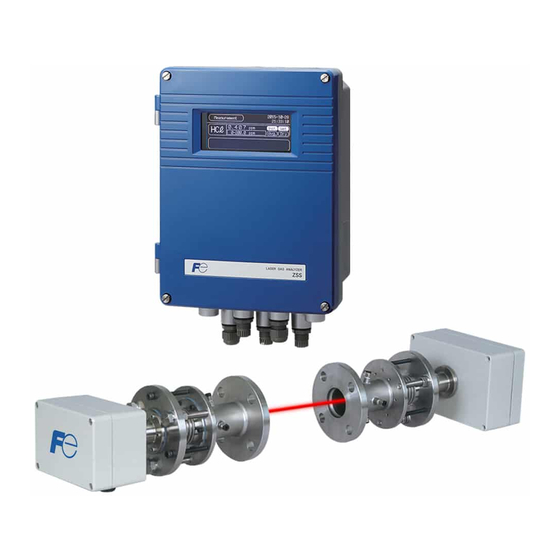
1. GENERAL 1.1 General Cross-stack laser gas analyzer (ZSS) provides continuous measurement of HCl in-flue gas incineration, NH density of denitration equipment and heat treat furnace, and O , CO, and CO density for combustion control within a short response time. The cross-stack configuration eliminates the need for transfer of the preparation measurement gas to the analyzer for proper measurement. -
Page 9: Checking Delivered Items
2. CHECKING DELIVERED ITEMS Upon receiving the recorder unit, check if the correct quantity of the accessories are supplied. Separately supplied document are given first priority. When you have purchased or want to purchase spare parts for 1-year operation or a list of calibration/installation fixtures, refer to “CAUTION ON SAFETY”at the end of this Manual. - Page 10 Control unit Receiver box Transmitter box Carton box Cable between receiver unit and control unit, Cable between receiver unit and transmitter unit Calibration gas cell Standard accessories Hexagonal socket bolt Angle adjustment unit Bolt, Nut, Spring washer Flat washer, Bolt for angle fine adjustment Power supply fuse - 3 - INZ-TN7ZSS-E...
-
Page 11: Name And Explanation Of Each Part
3. NAME AND EXPLANATION OF EACH PART 3.1 Overall composition The analyzer consists of 3 units; “Transmitter unit” to transmit the laser, “Receiver unit” to receive light, and “Control unit” to display and output signals. (4) Flange of angle adjustment (7) With bolt and nut (4) Flange of angle (2) Transmitter box... - Page 12 Name Description Receiver box A photodiode to receive light and a board are built-in. Transmitter box Laser element, peltier to control the temperature of laser and a board are built-in. Adjustment probe for received Terminal which checks the level of received light quantity with the voltage light quantity value when light axis adjustment is performed.
-
Page 13: Input/Output Terminal Of Control Unit (Excluding Co+O Analyzer)
3.2 Input/output terminal of control unit (excluding CO+O alyzer) Each input/output signal from the analyzer is connected to board terminal of the control unit. There are 2 types of the input/output terminal boards. Refer to the same figure that has the same terminal allocation as the product you received. - Page 14 AI terminal 1 AI1+ Analog input 1 (AI1) 2 AI1– 3 AI2+ Analog input 2 (AI2) 4 AI2– Cross sectional area of rated cable: 5 AI3+ Analog input 3 (AI3) AWG26-16 6 AI3– 7 AI4+ Analog input 4 (AI4) 8 AI4– AI expansion board 9 AI5+ required...
- Page 15 (2) Input / output terminal 2 (AO 2 points) External power AO terminal / AI terminal supply connection terminal (M4) / DI/DO terminal (equivalent to M2) External power supply connection terminal 1 100 to 240V AC (50/60Hz) (L) 2 100 to 240V AC (50/60Hz) (N) Screw diameter: M4 3 PE AO terminal...
- Page 16 AI terminal Screw diameter : Equivalent to M2 3 AI1+ 23 AI4+ Analog input 4 Analog input 1 4 AI1– 24 AI4– (AI expansion board repuired) 5 AI2+ 25 AI5+ Analog input 5 Analog input 2 6 AI2– 26 AI5– (AI expansion board repuired) 7 AI3+ Analog input 3...
-
Page 17: Input/Output Terminal Of Control Unit
3.3 Input/output terminal of control unit (CO+O analyzer) External power AO terminal / AI terminal supply connection terminal (M4) / DI/DO terminal (equivalent to M3) External power supply connection terminal 1 100 to 240V AC (50/60Hz) (L) 2 100 to 240V AC (50/60Hz) (N) Screw diameter: M4 3 PE AO terminal... - Page 18 AI terminal Screw diameter: Equivalent to M3 5 AI1+ 21 AI2+ Analog input 1 Analog input 2 6 AI1– 22 AI2– DI/DO terminal Screw diameter: Equivalent to M3 7 DO1 Low Light Transmission 8 DO1 9 DO2 Analyzer faulty 10 DO2 11 DO3 On Hold / Under Calibration 12 DO3...
-
Page 19: Mounting Method
4. MOUNTING METHOD ANGER This analyzer is not explosion-proof. Do not use it in an atmosphere of ex- plosive gas. Otherwise, it can result in serious accidents such as explosion, fire, etc. AUTION The analyzer should be installed in a place conforming with the installa- tion requirements noted in this instruction manual. -
Page 20: Installation Conditions
4.1 Installation conditions 4.1.1 Installation conditions of receiver unit and transmitter unit 4.1.1 Installation conditions of receiver unit and transmitter unit Select a location that meets the following conditions. Ambient temperature : A place where the temperature is within -20 to 55°C and there is no sudden temperature change. - Page 21 4.1.2 Installation conditions of control unit Select a location that meets the following conditions. Ambient temperature : –5 to 45°C Ambient humidity : 90 % RH or less Power supply : Rated voltage : 100V to 240V AC Rated frequency : 50Hz/60Hz Avoid a place that receives heavy vibration.
-
Page 22: Mounting Dimensions Of Receiver Unit And Transmitter Unit
4.2 Mounting dimensions of receiver unit and transmitter unit Mount the receiver unit and the transmitter unit in a place which has ample free space for maintenance and check as in the figure below (Fig. 4 - 1). Stack a: Inner diameter of ø50mm or more Companion flange (*5) b: 20 to 70mm (*1) c: Approximately 200 to 250mm (*2) -
Page 23: Mounting Range Of Companion Flange
4.3 Mounting range of companion flange (in factory range) Mount the companion flange so that it satisfies the conditions of the following figure (Fig. 4 - 2). If the con- ditions below are not satisfied, light cannot be received even if the light axis adjustment is performed by the angle adjustment unit. -
Page 24: Installation Procedure
4.5 Installation procedure Install equipments, referring to the following procedure. Item Page Check that the installation location for each equipment satisfies the contents in “4.1 In- P.13 stallation conditions”. ↓ Check that the installation location for the receiver unit and the transmitter unit satisfies P.15 the contents in “4.2 Mounting dimensions of receiver unit and transmitter unit”. - Page 25 (14) Adjust the light quantity so that the light quantity value becomes the neighborhood of P.27 the voltage value of the light quantify which is described in a nameplate. If the angle is adjusted with the furnace operated, it may not become the neighborhood of the light quantity value described in a nameplate due to the effect of dust, etc.
-
Page 26: Checking Received Light Quantity
4.6 Checking received light quantity (1) Remove the probe cap adjusting the received light quantity (BNC receptor) of the receiver unit, and connect it to the digital voltmeter using the BNC cable for light axis adjustment. (2) Read the DC voltage value. (3) The voltage value, where zero gas is supplied with the calibration cell connected, becomes the refer- ence light quantity value of light axis adjustment which is performed after the equipment is attached to a companion flange (Factory-set voltage is described on a nameplate which is labeled on covers of the... -
Page 27: Angle Adjustment
4.7 Angle adjustment Bellows Anchor nut Fixing bolt Optical axis adjusting tool A flange B flange Fig. 4-4 4.7.1 How to operate the angle adjustment unit 1 (1) When you tighten the B flange Turn the fixing bolt and the anchor nut clockwise at the same time. If it is difficult to turn them, slightly loosen the anchor nut first. - Page 28 4.7.2 How to operate the angle adjustment unit 2 This section describes movement of the optical axis by operating the angle adjustment unit. Example) When you adjust the fixing bolt and the anchor nut shown in the figure below, encircled with a solid line (1) If the flange A and the flange B are parallel, the laser beam points horizontal direction.
- Page 29 4.7.3 Adjustment procedure 4.7.3.1 When an optical axis adjusting tool (laser pointer) is used AUTION Do not watch the laser pointer beam directly with the optical measuring device. Otherwise, it may cause serious damage to your eyes. (1) When A and B flanges shown in Fig. 4 - 4 are extremely tilted, adjust them in a flat place so that they are parallel to each other.
-
Page 30: Piping System Diagram
4.8 Piping system diagram Or air-set box Copper or SUS pipe (not supplied) 2-Flowmeter Instrumentation airline joint (not supplied) (option) Filter regulator (option) 20 to 100L/min ø10/8 Teflon pipe Instrumentation (not supplied) air inlet (6) Purging gas inlet (with bell-and-spigot Mist separator joint for ø10/8) (option) -
Page 31: Assembly Of Receiver Unit And Transmitter Unit
4.9 Assembly of receiver unit and transmitter unit (1) Prepare “Receiver box or transmitter box” and “Hexagonal socket bolt” as shown in the following fig- ure (Fig. 4 - 10). (Check that the O-ring is mounted on near the lens (refer to Figure below) of the re- ceiver unit or the transmitter unit) (2) Mount “Receiver box or transmitter box”... -
Page 32: Wiring Connection
4.10 Wiring connection 4.10.1 Connecting Receiver / Transmitter cable The receiver unit and the transmitter unit are connected with the “Cable between receiver unit and transmit- ter unit”. Both ends of it are fitted with a female 16-pin connector (waterproof type). The connector has no polarity. Fix the Cable between receiver unit and transmitter unit to the stack, etc. - Page 33 4.10.2 Connecting cable between receiver unit and control unit The receiver unit and the control unit are connected with the “Cable between receiver unit and control unit”. Both ends of it are fitted with a female 10-pin connector (waterproof type). The connector has no polarity. Perform wiring in the way that the cable between receiver unit and control unit is not pulled.
-
Page 34: Adjustment Of Light Quantity
4.11 Adjustment of light quantity Note that if you loosen more than one fixing bolts or anchor nuts at a time to adjust, it takes a lot of time to resetting. 4.11.1 When an optional optical axis adjusting tool (laser pointer) is used for angle adjustment (1) Connect the digital voltmeter using the BNC receptor cable, referring to “4.6 Checking received light quantity”. - Page 35 4.11.2 When an optional optical axis adjusting tool (laser pointer) is not used (1) Connect the digital voltmeter using the BNC receptor cable, referring to “4.6 Checking received light quantity”. (2) The reference light quantity is based on the output in zero calibration or voltage value of light quantity which is described in a nameplate.
-
Page 36: How To Use The Bolt For Angle Fine Adjustment
4.12 How to use the bolt for angle fine adjustment (standard accessory) This bolt is used for adjustment when the light path length in the stack is long and when the quantity of light misses too much at the time of retightening in the procedure in “4.11 Adjustment of light quantity”. When each retightening is finished, perform fine adjustment by pressing with this bolt. -
Page 37: Connecting To Control Unit
4.13 Connecting to control unit 4.13.1 AC power connection AC power connecting terminal is positioned at the lower left of the control unit (see Fig. 4 - 15.). Use the AC cable for which flame resistance is 600V, 1.25mm (16AWG) or more, and the cable out diameter size is ... - Page 38 4 to 20mA DC, 1 to 5V DC, etc, according to the ordering contents. For connection of the signal cable, use a shielded wire or an insulated converter (LDC-16H01, manufactured by Fuji Electric Technica Co., Ltd. or equivalent) to supress the influences by noise.
-
Page 39: Explanation Of Operation Panel And Screen
5. EXPLANATION OF OPERATION PANEL AND SCREEN 5.1 Name and description of operation panel isplay area LASER GAS ANALYZER MODE (1) ode key (3) Up key (5) Side key (2) Escape key (4) Down key (6) Entry key Name Description of functions Name Description of functions (1) Mode key... -
Page 40: Screen Configuration
5.2 Screen configuration Measurement MODE Menu Output Hold Zero Calibration Span Calibration Alarm Log Parameter Setting Input Signal Alarm Setting AO Select Analyzer Information Password Display/Output 1 Component 2404 + AO Adjustment AI Adjustment Each Alarm Setting (Select each function screen by and press Zero/Span Parameter Setting... -
Page 41: Outline Of Screen
5.3 Outline of screen 5.3.1 “Measurement” screen (appears when the power is turned ON) On the MEASURE screen, measurable component, alarm, conversion measurable component, and analog input are displayed beginning at the top. When more than five items are displayed, switch the screen by key or key. - Page 42 5.3.1.1 Name (functions) (1) Measurable component ····· Displays the gas component to be measured in element symbol. (2) Concentration value ····· Displays measured value of concentration. The value is highlighted during the hold. (3) Unit ····· Displays the unit of concentration such as ppm, vol%, etc. (4) Instantaneous ·····...
- Page 43 5.3.2 “Menu” screen 2006-04-01 Menu 12:00:00 Zero Calibration Parameter Setting Span Calibration Display/Output Alarm Log Input Signal Alarm Setting AO Select (10) Output Hold Analyzer Information Pasword Press the key while the “Measurement” screen is displayed, and the “Menu” screen appears. (It does not appear when pressing the key while other screen is displayed.
- Page 44 5.3.3 “Alarm Record” screen 2006-04-01 12:00:00 Alarm Over H-Limit 1 04 01 13:23 LD Temp. Error 03 29 11:01 03:23 Select Delete All Delete The screen displays the alarm record occurred in the past. The ten newest errors are logged. The oldest error will be deleted one by one every time a new alarm occurs.
- Page 45 5.3.3.2 Basic Operation Moving the cursor 2006-04-01 Alarm Record 12:00:00 Date Alarm Day Repair Over H -Limit 1 04 / 01 11:23 HC ℓ LD Temp. Error 03 / 29 23:14 03:23 HC ℓ Press. AI Under 03 / 25 15:23 13:28 03 /...
- Page 46 Selected alarm deletion 2006-04-01 Alarm Record 12:00:00 Date Alarm Day Repair Over H -Limit 1 04 / 01 11:23 HC ℓ LD Temp. Error 03 / 29 23:14 03:23 HC ℓ Press. AI Under 03 / 25 15:23 13:28 Low Air Purge 03 /...
- Page 47 All alarms deletion 2006-04-01 Alarm Record 12:00:00 Date Alarm Day Repair Over H -Limit 1 04 / 01 11:23 HC ℓ LD Temp. Error 03 / 29 23:14 03:23 HC ℓ Press. AI Under 03 / 25 15:23 13:28 Low Air Purge 03 /...
- Page 48 5.3.3.3 Alarm types Following types of alarm are displayed. All the alarms except “Connection Error” which indicates communication failure between the receiver unit and the control unit will be activated after at least five minutes from the power off. The alarm of “Low Light Transmission”...
- Page 49 Alarm display Alarm contents Probable causes Box Temp. Warning It is reported when the temperature • The unit is used at an installation loca- in the receiver unit and the trans- tion exceeding the set range. mitter unit exceeds the temperature •...
-
Page 50: Zero Calibration And Setting
6. ZERO CALIBRATION AND SETTING 6.1 Zero calibration Select “Zero Calibration” from the “Menu” screen and press the key. 2006-04-01 2006-04-01 Zero Calibration Menu 12:00:00 12:00:00 Component Zero Calibration Parameter Setting Cell Length 1000 Span Calibration Display/Output Cal.Gas Value 0000 Input Signal 00.12 Alarm Log... - Page 51 Stack Transmitter box Receiver box (3) Mount the removed receiver box and transmitter box using the hexagonal bolt. (4) If the cable between receiver unit and transmitter unit or the Cable between receiver unit and control unit is fixed and not usable, provide them for calibration. (5) Wiring should be performed as following figure.
- Page 52 (6) Mount the Rc1/8 joint to the calibration gas cell, and connect one side to the standard gas cylinder (N (7) If necessary, attach a thermometer or a pressure gauge to the outside to connect the output signal (4 to 20mA) to the control unit of Analog Input.
- Page 53 6.1.2 Zero calibration (1) If the power is OFF, turn it ON. (2) Check if the flow of N gas is approximately 1.5 to 2.0 L/min. (3) Display the “Zero Calibration” screen. (4) Point the to “Component”, and press the key.
- Page 54 6.1.3 Zero calibration of dust Zero calibration of dust is performed in a state that the receiver unit and the transmitter unit are attached to the stack. Thus, when dust exists in the stack, do not perform the zero calibration, perform only the span cal- ibration.
-
Page 55: Span Calibration
6.2 Span calibration Select the “Span Calibration” from the “Menu” screen and press the key. 2006-04-01 2006-04-01 Span Calibration Menu 12:00:00 12:00:00 Component Zero Calibration Parameter Setting Cal. Value Range 1 Span Calibration Display/Output Cell Length 0500 Cal.Gas Value Input Signal 0020.80 Alarm Log 0.000... - Page 56 6.2.2 About Span check (calibration) Gas absorption laws Based on Lambert-Beer Law I(L)=I(0)exp[-ks·ns·Ls] Absorption intensity is proportional to gas concentrationmeasured and the lengths I(L) : Received light quantity where the gas exists (measured optical path I(0) : Transmitted light quantity lengths or stack length) : Coefficient : Concentration value...
- Page 57 6.2.3 Span calibration (1) If the power is OFF, turn it ON. (2) Check if the flow of span gas is approximately 1.5 to 2.0 L/min. (3) Display the “Span Calibration” screen. (4) Point the to “Component”, and press the key.
- Page 58 6.2.4 Measurement of average dust concentration of the same time as the sampling for manual dust analysis conducted Matching the value obtained by manual analysis is required for measument of dust. Use “Average Dust Value” screen to measure the dust concentration of the same time as sampling for manual analysis was conducted.
- Page 59 6.2.4.1 The measuring procedure of average dust concentration to match the value obtained by manual analysis. 2006-04-01 Span Calibration 12:10:00 Component Dust Cal. Range Range 1 Cell Length Cal.Gas Value 1000.00 vol% Meas. 100.00 vol% Gas Temp. 0025 °C Point the cursor to [Component] on the Gas Press.
- Page 60 2006-04-01 Average Dust 12:10:00 Start Time 06/04/01 12:10 Sampling Time 100.0 mg/m Meas. 0.000 mg/m Move the cursor to [Start Time], and press key to fix the setting of [Start Time] and [Sampling Time]. Last time sampling day Start Average dust concentration of the setup con- Finish 06/04/01 00:00:00 dition will be measured.
- Page 61 6.2.5 Matching a value obtained by manual dust analysis It may take several days until the result of manual analysis is obtained. After the result of manual analysis is obtained, the concentration of dust average value measured while sampling gas for manual analysis was be- ing extracted should be matched.
- Page 62 2006-04-01 Span Calibration 12:10:00 Component Dust Cal. Range Range 1 Cell Length Cal.Gas Value 1000.00 vol% Meas. 100.00 vol% Gas Temp. 0025 °C Gas Press. 00.00 Move the cursor to [Span Cal. Start], and Span Cal.Start Ave. Dust Value press the key.
- Page 63 6.2.6 Method of H O calibration There is no cylinder for span calibration of H O, thus manual analysis is required. Calibration is conducted under the condition of installing receiver /transmitter unit. Calibration cell is not used. 6.2.6.1 Required data Please prepare for following required data for span calibration.
- Page 64 6.2.6.3 Procedure of span calibration 2007-04-13 Menu 12:10:00 Zero Calibration Parameter Setting Span Calibration Display/Output Input Signal Alarm Log Alarm Setting AO Select Point the cursor to [span calibration] with Output Hold On [Menu mode] and then press Pasword 2007-04-13 Span Calibration 12:10:00 Component...
- Page 65 2007-04-13 Span Calibration 12:10:00 Component Cal. Range Range 1 Cell Length Point the cursor to [cal] with 1500 Cal.Gas Value 7.500 vol% then let the inputting display part of gas Meas. 5.00 vol% concentration blink with Gas Temp. 0015 °C Input the results of gas concentration from Gas Press.
- Page 66 2007-04-13 Span Calibration 12:10:00 Component Cal. Range Range 1 Cell Length 1500 Cal.Gas Value 7.50 vol% Meas. 5.00 vol% Gas Temp. 0025 °C Gas Press. 00.00 Point the cursor to [Span Cal Start] with Span Cal.Start and then press Cal.Finish LastCal.Day 2006/09/01 2007-04-13...
-
Page 67: Alarm Setting
6.3 Alarm setting Select “Alarm Setting” from the “Menu” screen, and press the key. On the “Alarm Setting Gas” screen, select the measurable component by moving the with the key and the key. Press the key after measurable component is selected. “Alarm Setting” screen is displayed. 2006-04-01 2006-04-01 Alarm Setting... - Page 68 2006-04-01 Alarm Setting 12:00:00 Range1 50.00 H- Limit Range2 30.00 10.00 Range1 L-Limit 00.00 Range2 Hysteresis Select “ON” or “OFF” by the key or the Analog Output Range2 H-Limit Alarm Record key, and press the key. 2006-04-01 Alarm Setting 12:00:00 Range1 50.00 H- Limit...
- Page 69 2006-04-01 Alarm Setting 12:00:00 Range1 50.00 H - Limit Range2 30.00 10.00 Range1 L-Limit 00.00 Range2 Hysteresis Select “ON” by the key or the key, Analog Output Range2 H - Limit and press the key. Alarm Record 2006-04-01 Alarm Setting 12:00:00 Range1 50.00...
- Page 70 2006-04-01 Alarm Setting 12:00:00 Range1 60.00 H- Limit Range2 30.00 10.00 Range1 L-Limit 00.00 Range2 Hysteresis Double-click the key, and the returns Analog Output Range2 H-Limit Alarm Record to the previous position. Note Set the value so that H-Limit is larger than L-Limit, and that (H-Limit – L-Limit) is larger than hysteresis width.
- Page 71 2006-04-01 Alarm Setting 12:00:00 Range1 50.00 H- Limit Range2 30.00 10.00 Range1 L-Limit 00.00 Range2 Hysteresis Select output range by the key and the Analog Output Range1 H - Limit Alarm Record key, and press the key. 2006-04-01 Alarm Setting 12:00:00 Range1 50.00...
- Page 72 2006-04-01 Alarm Setting 12:00:00 Range1 50.00 H - Limit Range2 30.00 10.00 Range1 Change the numeric value by the key or L-Limit 00.00 Range2 key, and move the digit by the Hysteresis key. Analog Output Range2 H-Limit Alarm Record Press the key to make the hysteresis valid.
-
Page 73: Output Hold
6.4 Output hold Select “Output Hold” from the “Menu” screen, and press the key. 2006-04-01 2006-04-01 Output Hold Menu 12:00:00 12:00:00 Zero Calibration Parameter Setting Span Calibration Display/Output Input Signal Alarm Log Alarm Setting AO Select Output Hold Analyzer Information Pasword 6.4.1 Output hold Set output hold to “Last Meas.”... - Page 74 2006-04-01 Output Hold 12:00:00 When “Last Meas.” is selected, cursor returns to the starting position. HCℓ Pre-set When “Pre-set” is selected, numeric value is highlighted. Change the numeric value by the key or the key, and move the digit to the right by the key.
- Page 75 6.4.2 Remote hold (DI3 terminal) Output hold can be performed by remote according to the external contact input (DI3 terminal, option). The value to hold output is “Last Meas.” only. 2.0s or more 2.0s or more 2.0s or more Short-circuit Remote hold signal Open 2.0s...
-
Page 76: Parameter Setting
6.5 Parameter setting On the “Parameter Setting” screen, “Path Lengths” related to measurement value and “Average Period” re- lated to average value output are set. Items to be set are as follows. Explanation of setting items “Path Lengths” : Enters the optical path lengths. “Average Period”... - Page 77 Stack lengths (mm) Transmitter unit Receiver unit Campanion flange 2006-04-01 Parameter Setting 12:00:00 Path lengths 01000 Average Period Min. cv O Reset Avg.Gas Key Lock Point the to “Path Lengths” by the Disp.OFF Min. and the key, and press the key.
- Page 78 6.5.2 Setting of moving average time When the indication value and output value are set to the average value in the “6.6.1 Setting of instantane- ous/average value”, set how many minutes the value should be held as a moving average value. Setting range is from 1 to 60 minutes.
- Page 79 6.5.3 Average value reset When the indication value and output value are set to the average value in the “6.6.1 Setting of instantane- ous/average value”, reset the average value to clear the measurement value and the O conversion value. When the indication value and the output value are set to the instantaneous value, nothing is changed even if average value is reset.
- Page 80 Remote average value reset (DI1 terminal) Apply rectangular waveform voltage (pulse width: 2.0 sec or more) to the input terminal of remote average value reset (DI1 terminal, option) to reset the average value. 2.0s or more 12 to 24 VDC/ 5 to 20 mA Remote hold signal Starts average value reset...
- Page 81 6.5.5 Setting of backlight OFF Automatic OFF setting of the backlight of the LCD unit can be made. If the specified time elapses since the measurement screen has been resumed, the backlight is automatically turned off. Continuous lighting time of LCD (liquid crystal display) is approximately 58000 hours. Press any key to reset backlight OFF.
-
Page 82: Display/Ao Setting
6.6 Display/AO setting Make a setting of “Inst./Avg.” or “Wet/Dry” of the measurement value displayed on the “Measurement” screen. Explanation of setting items “Inst./Avg.” : Make a setting of “instantaneous value” or “average value” for each measur- able component. “Wet/Dry” : Make a setting of “Wet”... - Page 83 Input switching of the remote instantaneous/average value (DI2 terminal) Apply rectangular waveform (pulse width: 2.0 sec or more, pulse interval: 2.0 sec or more) to the input terminal of remote average value to switch the instantaneous value and the average value. If the previous measured value is set as instantaneous value, and O correction value is set as average val- ue, the previous measured value becomes the average value, and the O...
- Page 84 2006-04-01 Display/AOSetting 12:00:00 Inst. Range Control Avg. Range1 0 ~ 50.0 ppm Inst. Remote HCℓ Range2 0 ~ 1000ppm Range1 0 ~ 50.0 ppm Inst. HCℓ Range2 0 ~ 1000ppm Select “Inst.” or “Avg.” by the key or the key. Press the key to move the cur- sor to “Wet/Dry”...
- Page 85 2006-04-01 Display/ AOSetting 12:00:00 Inst. Range Control Avg. Range1 0 ~ 50.0 ppm HCℓ Avg. Remote Range2 0 ~ 1000ppm Range1 0 ~ 50.0 ppm key can move the cursor backward in Inst. HCℓ Range2 0 ~ 1000ppm the middle of the setting. The setting fixed by the key does not return to the previous setting, even if the cursor is moved by the key.
-
Page 86: Analog Input
6.7 Analog input Makes a setting of the analog input related to the measured gas conditions such as gas temperature. Input the sensor signal to the analog input terminal of the control unit, and the measured gas conditions can be cali- brated. - Page 87 2006-04-01 Analog Input 12:00:00 Fixed 20mA GasPress.(kPa) Fixed 00.00 00.00 10.00 Gas Temp.( ) Fixed 0027 0100 1000 Gas Flow(m/s) Fixed 02.00 00.00 20.00 Fixed 20.00 00.00 21.00 (vol%) Select the channel (CH1 or CH2) connected to AI Fixed 050.0 000.0 100.0 (vol%)
- Page 88 conversion Calculate O conversion from the set value of input signal for the oxygen (O ) analyzer. The calculation formula is as follow. Conversion C = (21 - On) / (21-Os) × Cs : Converted concentration Os : Measured O concentration On : Standard O concentration for conversion (If not specified at order: 12%)
- Page 89 6.7.2 Setting of analog input (fixed value) (in case of H Sets the fixed value to perform the calibration when the measured gas condition do not change, or the sensor inputs to calibrate are not provided, or the number of calibration input terminals is insufficient. When the actual value differs greatly from the setting value, analog input may not be measured correctly.
- Page 90 2006-04-01 Analog Input 12:00:00 Fixed 20mA GasPress.(kPa) Fixed 00.00 00.00 10.00 Gas Temp.( ) 0027 0000 0500 Gas Flow(m/s) Fixed 02.00 00.00 20.00 Fixed 20.00 00.00 21.00 (vol%) Fixed 020.0 000.0 100.0 (vol%) The same procedure can be implemented as for Alarm 20mA pressure gauge, thermometer or oxygen analyzer...
- Page 91 2006-04-01 Analog Input 12:00:00 Fixed 20mA GasPress.(kPa) Fixed 00.00 00.00 10.00 Enter the purge pressure value to output alarm. Gas Temp.( ) 0027 0000 0500 Gas Flow(m/s) Fixed 02.00 00.00 20.00 Change the numeric value by the key or Fixed 20.00 00.00 21.00...
-
Page 92: Selecting Analog Output
6.8 Selecting analog output There are two types of analog output (4 to 20mA DC output) as a standard specification. Measurement value and O conversion value can be output individually. Both of average value and instantaneous value can be output arbitrary. Default value is set to “No”, so be sure to set it after installation. - Page 93 6.8.2 Time setting Date and time setting can be made. 2006-04-01 Parameter Setting 12:00:00 Path lengths 01000 Average Period Min. Reset Avg.Gas Key Lock Point the cursor to “Date/Time” by the Disp.OFF Min. Date/Time 06/04/01 00:00:00 or the key, and press the key.
-
Page 94: Fine Adjustment Of Analog Output Value
6.9 Fine adjustment of analog output value This section explains the fine adjustment method of analog output. Since a slight discrepancy of analog out- put value may be caused, perform adjustment according to the following method. 2006-04-01 Menu 12:00:00 Zero Calibration Parameter Setting Point the cursor to "Password"... - Page 95 2006-04-01 FACTORY MENU 12:00:00 This device has the simulation output function. Output Zero Span Point the cursor to “Output Fine Tuning” at the Analog Output 1 0742 3484 bottom key. Select an item from “Meas Analog Output 2 0686 3429 Analog Output 3 0677 3431...
-
Page 96: Checking Alarm Output
6.10 Checking alarm output 6.10.1 Low Light Transmission (1 a contact output) Remove the receiver box or the transmitter box to generate “Low light Transmission” alarm. At this time, do not look into the transmitter box. Otherwise, it may cause serious damage to your retinae or cornea. -
Page 97: How To Use The Check Cell
6.11 How to use the check cell Check cell Transmitter unit Receiver unit Stack Control unit Laser gas analyzer with check cell (ZSS) Atmospheric (AO) release Sequencer Remote check input (AI) Supplies for checking span value on site cylinder Standard gas cylinder 6.11.1 Example of use of check cell The check cell is intended to be used to check a discrepancy of the span point without removing the device... - Page 98 Concentration You can not check the zero point while the gas to be measured remains in the stack Concentration output In order to check where the zero point is, the condition that "gas to be measured does not exist" must be required T: Time 6.11.2 Concentration of the gas which is fed to the check cell and gas concentration fluctuation...
- Page 99 6.11.3 Operation method (1) Remove the stopper at gas inlet and outlet of the check cell, and then connect with N gas cylinder. (2) Feed N gas to the check cell to obtain the measured gas concentration inside the stack. (3) Feed the gas, which was obtained by “6.11.2 Concentration of the gas which is fed to the check cell and gas concentration fluctuation”, to the check cell.
-
Page 100: Maintenance
Note that the Table 7 - 2 provides the guideline for maintenance items and intervals, assuming standard gas, operation, and installation environment. Only qualified personnel who have been trained by Fuji Electric should perform maintenance works. -
Page 101: Zero Calibration
7.3 Zero calibration Refer to “6.1 Zero calibration”. 7.4 Span calibration Refer to “6.2 Span calibration”. 7.5 Replacement of O-ring and packing Replace the packing, referring to the following figure. Replace the O-ring and silicon packing A annually. Receiver unit Transmitter unit Stac Silicon packing A... -
Page 102: Troubleshooting
8. TROUBLESHOOTING (1) “Low Light Transmission” alarm is occurred. → 1) When the light axis is adjusted, do the gas temperature and the temperature differ from each other too much? → Yes (The stack might have been deformed by the temperature, resulting in deflection of light axis. Re-adjust the light axis.) →... - Page 103 (6) “Gas Pressure (H-Limit)” alarm is occurred. → 1) Is the device used in a place where the gas pressure is out of the specified range? → Yes (The specified gas pressure for this device is ±10kPa. Take counter-measures such as changing a place to install it.) →...
- Page 104 → 8) Different measurement point may be the cause. →Yes (Manual analysis or sampling type analyzer analyzes concentration in the center of stack where the gas is sampled, while ZSS analyzes average concentration from edge to edge of the stack. Thus, non-uniformity of concentration distribution in the stack makes difference in concentration.) →...
-
Page 105: Appendix 1 Specifications For The Cross-Stack Laser Gas Analyzer
APPENDIX 1 SPECIFICATIONS FOR THE CROSS-STACK LASER GAS ANALYZER 1-1 Specifications Measurement principle : Non-dispersive infrared absorbance system (NDIR) Measuring method : Cross-stack system (path system) Object of setup : Incineration facilities, denitration equipment, etc. Measurable component and range: Measurable Min.measuring Max.measuring range Measured gas... - Page 106 (10) Material : Receiver/Transmitter unit: Aluminum, SUS316 Control unit: Aluminum (11) Materials of : SUS316, BK7, FKM, PTFE, glass-cloth, silicone gas-contacting parts (12) Air purge connection : RC1/4 (tube 10 × 8) diameter (13) Box finish color : Receiver/Transmitter box: gray Control unit cover: blue Control unit case: silver (14) Power supply...
- Page 107 1-2 Contact output contents (1) Low light transmission : Contact output is performed (off) when the amount of light transmis- (1 a contact) sion is insufcient. (2) Beyond the upper/lower : According to the preset upper or lower limit alarm value, contact limits output is performed (off) when it becomes lower than alarm up- (1 a contact)
- Page 108 1-5 Installation environment Ambient temperature : –20 to 55°C (Receiver unit/Transmitter unit), –5 to 45°C (control unit) Ambient humidity : 90% R.H. or less Measurable optical path : 0.5 to 10m (CO+O : 0.5 to 5 m) length (stack diameter) Standard flange : JIS10K 50A flange (JIS B 2212) Air purge...
-
Page 109: Appendix 2 Code Symbols
APPENDIX 2 CODE SYMBOLS - 102 - INZ-TN7ZSS-E... - Page 110 List for Combinations of Measureable Components, Units and Measurement ranges Component Measuring range 0 ~ 2, 2.5, 4, 5, 10, 15, 20, 25, 50 vol% CO (For use in high temp.) 0 ~ 10, 15, 20, 25, 50 vol% 0 ~ 10, 15, 20, 25, 50, 100, 200, 250, 400, 500, 1000, 2000, 5000 ppm or mg/m 0 ~ 2, 2.5, 4,5, 10, 15, 20, 25, 50 vol% (For use in high temp.) 0 ~ 10, 15, 20, 25, 50 vol%...
- Page 111 Spare parts for one year (ZBN1SS11) Parts name Quantity Remarks (type) Silicon packing A For bellows (ZZP*ZSSTK7N3508P1) O-ring (ZZP*ZSSTK7P2530P5) Calibration/installation fixture list (Option) Parts name Quantity Type Cable between receiver unit and control unit (for calibration) ZZP*ZSSTK4J1271C2 Cable between receiver unit and transmitter unit (for calibra- ZZP*ZSSTK4J0641C3 tion) Calibration gas cell (*3)
- Page 112 Stack (4) Optical axis adjusting tool (laser pointer) (4) Optical axis adjusting tool (target) Parts for adjusting the optical axis Transmitter unit (5) IR card IR CARD Laser beam (visible) Invisible light Invisible light / visible fixtures(for NH (6) Check cell Transmitter unit Receiver unit Stack...
- Page 113 (11) Air set box 4-φ11 (Mounting hole) Parts for air purge (7) Filter regulator (8) Mist separator Flow Mist separator Filter regulator meter Pipe with external diameter φ10 (IN) (OUT) (out of supply scope) (OUT) (OUT) (IN) (OUT) (IN) (IN) measuring instrument air inlet...
- Page 114 (13) BNC cable for optical axis adjustment - 107 - INZ-TN7ZSS-E...
- Page 115 (Outline Diagram) Or air-set box Copper or SUS pipe (not supplied) 2-Flowmeter Instrumentation airline joint (not supplied) (option) Filter regulator (option) 20 to 100L/min ø10/8 Teflon pipe Instrumentation (not supplied) air inlet Mist separator Approx. 400 150 to 200 (option) Flange of angle 150 to 200 Note 1...
Need help?
Do you have a question about the ZSS-7 and is the answer not in the manual?
Questions and answers