Table of Contents
Advertisement
Quick Links
Advertisement
Table of Contents

Related Manuals for Fuji Electric ZRE-2


Summary of Contents for Fuji Electric ZRE-2
- Page 1 Instruction Manual NDIR TYPE INFRARED GAS ANALYZAR TYPE: ZRE-2 INZ-TN2ZRE-E...
-
Page 2: Preface
• After reading through the manual, be sure to keep it near at hand for future reference. • This instruction manual should be delivered to the end user without fail. Manufacturer : Fuji Electric Co., Ltd. Type : Described in the nameplate on main frame... -
Page 3: Caution On Safety
CAution on sAFEty To operate the analyzer properly, be sure to read “Caution on Safety” carefully. • The descriptions listed here provide important information on safety. Be sure to observe them at all times. Those safety precautions are classified into 3 levels, “DANGER,” “CAUTION” and “PROHIBI- TION.”... - Page 4 Caution on piping Be sure to observe the following precautions while installing DANGER piping. Improper piping may result in gas leakage. If the leaking gas contains a toxic component, serious acci- dents may result. If it contains combustible gases, explosion or fire may result.
- Page 5 Caution on use • Do not touch the input/output terminals with metal or finger. PROHIBITION Otherwise, electric shock or injury may result. • Do not smoke or use flames near the analyzer. Otherwise, fire may result. • Do not allow water to enter the analyzer. Otherwise, electric shock or internal fire may result.
-
Page 6: Table Of Contents
ContEnts PREFACE ........................i CAUTION ON SAFETY ....................ii CONTENTS ......................... v OVERVIEW ......................1 NAME OF DELIVERED ITEMS AND EACH PARTS ........2 Confirmation of delivered items ................2 Name and description of analyzer ................3 INSTALLATION ....................5 Installation conditions .................... 5 Installation ...................... - Page 7 Alarm setting ......................34 6.3.1 Setting of alarm values ................34 6.3.2 Hysteresis setting ..................36 Setting of auto calibration ..................37 6.4.1 Auto calibration ................... 37 6.4.2 Forced run/stop of auto calibration .............. 40 Setting of auto zero calibration ................42 6.5.1 Auto zero calibration ...................
-
Page 8: Overview
1. oVERViEW This infrared gas analyzer (type: ZRE) has been tested to the requirements of UL 61010-1/CSA-C22.2 No.61010-1, second edition, including Amendment 1, or a later version of the same standard incorporat- ing the same level of testing requirements. This instrument measures the concentration of NO, SO , CO , CO and CH contained in sampling gas on... -
Page 9: Name Of Delivered Items And Each Parts
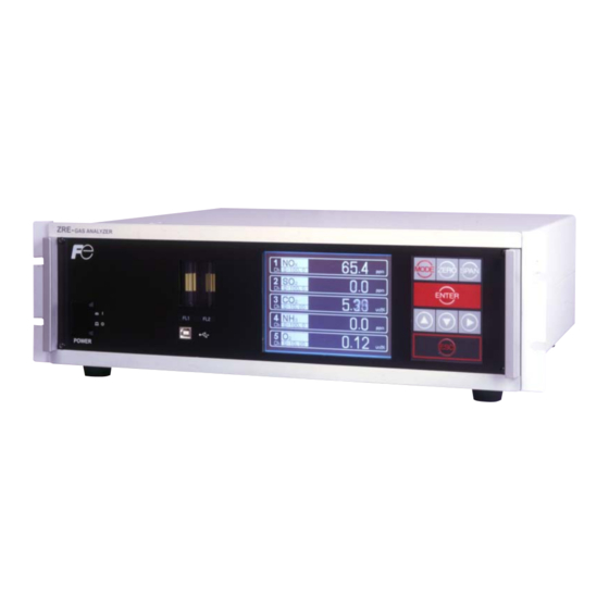
2. nAME oF DELiVERED itEMs AnD EACH PARts 2.1 Confirmation of delivered items ZRE- GAS ANALYZER MODE ZERO SPAN Analyzer: 1 unit ENTER POWER Standard: IEC127-2 Size: ø5 × 20mm Fuse: 2 pcs Rating: 250V/2A delay type Part No.: TK7L7571P3 25 pin D-sub connector (male) Analog output connector: 1 Part No.: TK7N3059P8... -
Page 10: Name And Description Of Analyzer
2.2 name and description of analyzer <standard model> ③ Flow meter ANALYZER MODE ZERO SPAN ENTER < Front panel > POWER ② Display/operation panel ① Power switch ④ USB connector ⑤ Purge gas inlet ⑪ Communication connector (RS-485) ⑥ Sampling gas inlet (2 systems) ⑫ Analog output connector (A /O) ⑩ External input ⑦ Sampling gas outlet (2 systems) (D-sub25 pin) - Page 11 <in case of uL model> ③ Flow meter ANALYZER MODE ZERO SPAN ENTER < Front panel > ② Display/operation panel ④ USB connector ⑤ Purge gas inlet ⑪ Communication connector (RS-485) ⑥ Sampling gas inlet (2 systems) ⑫ Analog output connector (A / O) ⑩ External input ⑦ Sampling gas outlet (2 systems) (D-sub25 pin) connector DIO3...
-
Page 12: Installation
3. instALLAtion DANGER This unit is not explosion-proof type. Do not use it in a place with explosive gases to prevent explosion, fire or other serious accidents. CAUTION • Entrust the installation, movement or re-installation to a specialist or the supplier. A poor installation may cause accidental tipover, electric shock, fire, injury, etc. -
Page 13: Installation
3.2 installation 3.2.1 installation of analyzer main frame Installation methods for the analyzer main unit are divided into 2 types; (Unit : mm) Type External dimensions Mounting dimensions Mounting method 19-inch rack mounting ANALYZER MODE ZERO SPAN ENTER 450 or more Support “A”... -
Page 14: Piping
3.3 Piping CAUTION In addition to a sample gas inlet and outlet, there is a purge gas inlet at the rear panel of the analyzer. When improper connection is carried out here, combustible gas, poisonous gas, and explo- sive fumes may be accumulated into the analyzer. Observe the following when connecting the gas tube. - Page 15 Internal piping diagram Optical unit 2 (IR Unit 2) Optical unit 1 (IR Unit 1) Built-in sensor INLET1 OUTLET1 Sampling gas outlet Sampling cell Note) Sampling gas inlet 2 cells may be used by combination of range. Correspondence of measured components and optical units Measuring components Optical unit 1 Optical unit 2...
-
Page 16: Sampling
3.4 sampling 3.4.1 Conditions of sampling gas (1) Dust contained in the sampling gas should be completely removed with a filter. For the final stage filter, use a filter that allows removing dust particles of 0.3µm. (2) Dew point of the sampling gas must be lower than the ambient temperature to avoid occur- rence of drain in the gas analyzer. -
Page 17: Pressure At Sampling Gas Outlet
The following illustrates a typical system configuration for five component gas measurement for monitoring combustion exhaust gas from boiler, refuse incinerator, etc. Contact Fuji Electric for system configuration matching the particular use or further information. (1) Gas extractor ZRE unit... -
Page 18: Wiring
3.5 Wiring CAUTION • Be sure to turn off the power before installing wiring. Otherwise, electric shock may result. • Be sure to perform protective earth connection. Otherwise, electric shock or failure may result. • Select a proper wiring material that satisfies the ratings of the instrument. Otherwise, elec- tric shock or fire may result. - Page 19 (1) Power supply (standard terminal 1 to 2) Connect the given power supply to the power terminal, and connect the ground wire to the ground- ing terminal (standard terminal 3). Be sure to perform protective earth connection. Use solderless terminals (for M3.5) for connection to the terminals (power and earth). The infrared gas analyser: Please install an accessory ferrite core (To the power supply terminal stand side) on the power supply wiring line of ZRE.
- Page 20 (2) Analog output signal: Analog output connector (A/o) Output signal : 4 to 20 mA DC or 0 to 1 V DC (selected when ordering) Minus lines for the insulation and signal are common from the ground and inter- nal circuit Allowable load : 4 to 20 mA DC, 550Ω...
- Page 21 (3) o sensor input: External input connector (A/i) Input signal: External zirconia O analyzer : Zirconia O sensor signal (Fuji ZFK7 output) External O analyzer 0 to 1 V DC (DC input resistor of 1MΩ or more) < External input > A/I connector (O sensor input) ●...
- Page 22 (4) Contact input/output (Dio): digital input/output connector (DIO1 to 3) Contact input signal : Voltage is applied from the external 12 to 24 V DC, max 15mA Photo-coupler insulation (from each DI and ground) Contact capacity : C contact relay output 24V/1A AC/DC resistive load <...
- Page 23 • Insulation output (from each DO and ground) To avoid external interference, wiring of analog output signal, O sensor input and contact input should be fixed separately from that of power supply and contact output. Note) To avoid the effect of noise generated from external units, be sure to ground the analyzer main unit.
- Page 24 2) In case of automatic calibration (example shown in Item 6.4.1, Automatic calibration settings) Automatic Ch1 span Ch3 span calibration Ch5 span calibration calibration start calibration Ch4 span Ch2 span Zero calibration calibration calibration Zero gas Zero calibration output 350 s Ch1 span calibration output Ch1 span gas 350 s...
-
Page 25: Operation
4. oPERAtion 4.1 Preparation for operation (1) tube and wiring check Double-check if tubes of the gas sampling and exhaust ports are correctly connected. Double-check for proper wiring. 4.2 Warm-up operation and regular operation (1) operation procedure 1) Turn ON the power switch on the left side when facing the front panel of the analyzer unit. The measurement screen appears on the front display panel in 1 to 2 seconds. -
Page 26: Description Of Display And Operation Panels
5. DEsCRiPtion oF DisPLAy AnD oPERAtion PAnELs This section describes the display unit and operation panel of the analyzer unit. It also explains the name and description of function on the operation panel. 5.1 name and description of operation panel Display unit ANALYZER MODE... -
Page 27: Overview Of Display And Operation Panels
5.2 overview of display and operation panels • Measurement mode * 1) The panel configuration is changed depending on the display channel. (The measurement mode screen can be viewed by scrolling the arrow key up and down). ZERO ZERO Calibration •... -
Page 28: Outline Of Display Screen
5.3 outline of display screen (1) Measurement mode screen (appears when the power is turned on) The measurement screen depends on the number of components. The following screen configura- tion as shown as an example is for NO, SO , CO , CO and O (output: 12 channels). - Page 29 ● Instantaneous value and concentration value: The concentration display of Ch (component) where sampling components such as “CO ”, “CO” and “O ” are displayed in the component display, indicates current concentration values of the measured components contained in gas that is now under measurement. ●...
- Page 30 (3) Contents of measured channel (Ch) The following table gives measurement channels and their contents according to the symbols. Code symbol 6th digit 7th digit 21st digit Display/output contents 1 to 3 Ch1:O Ch1:NO Ch1:SO Ch1:CO Ch1:CO Ch1:CH Ch1:NO, Ch2:SO Ch1:NO, Ch2:CO Ch1:CO , Ch2:CO...
-
Page 31: Basic Operation
5.4 Basic operation • Measurement mode The measurement mode can be displayed 0 0 . up to 5 channels in a single screen. If 5 0-200 0 0 . channels or more are to be displayed in a 0-200 single screen, press the or the 0 0 0 0-10... -
Page 32: Setting And Calibration
6. sEttinG AnD CALiBRAtion 6.1 switch of range 6.1.1 setting of range switch mode MODE Set the range switch mode as follows. (1) Press the key in measurement mode MODE to display the User mode screen. (2) Move the cursor to “Switch Ranges” and press the key. -
Page 33: Manual Range Switch
6.1.2 Manual range switch The range of the measured component can be switched manually as follows. (1) Select “MR” as range switch mode, and then press the key. (2) Move the highlight of the cursor to range selection, and then select a desired range by pressing the or the key. -
Page 34: Calibration Setting
6.2 Calibration setting This mode is used to set calibration concentration and actions. The calibration setting involves cali- bration concentration, zero calibration, calibra- tion range and auto calibration component/range. In the “Calibration Parameters” screen that ap- pears, the data shown at right is illustrated. 6.2.1 setting of calibration concentration It allows you to set concentrations of the stan- dard gas (zero and span) of each Ch used for... - Page 35 (4) Then, enter calibration gas concentration values (zero and span). For value entry, press Cursor for setting value or the key, and a 1-digit value increases or decreases. By pressing the key, the digit moves. After setting, save the entry by pressing the key.
-
Page 36: Setting Of Manual Zero Calibration
6.2.2 setting of manual zero calibration When zero calibration is made manually, set either all measurement components should be cali- brated simultaneously or each component should be calibrated while selecting one by one. (1) Select < User mode > → < Calibration parameters >... - Page 37 Manual Calibration screen • When setting all components to “each”: • When setting all components to “at once”: A single cursor will appear. Cursors will appear at all components where “at once” is set. INZ-TN2ZRE-E...
-
Page 38: Setting Of Calibration Range
6.2.3 setting of calibration range This mode is used to set if the range of each Ch (component) at the zero or span calibration (manual or auto calibration) should be calibrated with a single range or 2 ranges. (1) Select < User mode >→ < Calibration parameters >... -
Page 39: Setting Of Auto Calibration Component/Range
6.2.4 setting of auto calibration component/range Select the Ch (component) and the range with which auto calibration is to be performed. The Ch for which “AR” has been selected as range switch mode is calibrated in the range set here even when manual calibration is performed. - Page 40 To close the setting Press the key to exit automatic calibration component/range setting, and the previous screen appears. Operation by setting Auto calibration is performed under the following rules. 1. Zero calibration is performed at the same time, for the Ch (component) with which “enable” is selected at the time of auto calibration and auto zero calibration.
-
Page 41: Alarm Setting
6.3 Alarm setting 6.3.1 setting of alarm values The High/Low limit alarm output setting for the measured concentration setting can be made. Arbitrary 5 alarm contact outputs can be used. To change alarm setting, set the alarm ON/OFF setting to OFF, and then change the value. (1) Enter the “Setting of Alarm No.”... - Page 42 Description of setting items The alarm contact assigned the same number as the alarm is operated accordingly. Channel: Channel setting targeted for issuance of alarm. One Ch No. can be selected for multiple alarms. H-Limit value: Sets the high limit value (concentration) of alarm. L-Limit value: Sets the low limit value (concentration) of alarm.
-
Page 43: Hysteresis Setting
6.3.2 Hysteresis setting To prevent chattering of an alarm output near the alarm setting values, set the value of hysteresis. (1) In the “Alarm Setting” screen that ap- pears, point the cursor to “Hysteresis” by pressing the or the key. Press the key to display the screen shown at right. -
Page 44: Setting Of Auto Calibration
6.4 setting of auto calibration 6.4.1 Auto calibration Auto calibration is automatically carried out at the time when zero span calibration are set. Before changing the setting of auto calibration, set the ON/OFF to OFF. (1) Enter the “Setting of Auto Calibration” screen from the user mode, and the display shown at right appears. - Page 45 <Gas flow time> setting (1) Press the key in a state where the cur- sor is placed preceding “Flow Time,” and the flow time setting screen appears. (2) Move the cursor to the gas you want to change by pressing the or the key, and then press the...
- Page 46 Auto calibration status contact output is closed during auto calibration (NO side), and is open in other cases. Example 12:00 Start Time Cycle 350 sec Flow Time Zero 350 sec Ch1 Span 350 sec Ch2 Span 350 sec Ch3 Span 300 sec Ch4 Span 300 sec...
-
Page 47: Forced Run/Stop Of Auto Calibration
6.4.2 Forced run/stop of auto calibration Auto calibration can be performed just once or forcibly stopped while the calibration is performed. 6.4.2.1 Execution of auto calibration (only once) (1) In the “Setting of Auto Calibration” screen that appears, point the cursor to “Auto Calibration Run”... - Page 48 “Auto Calibration” screen Example In case where setting the auto calibration components (see Item 6.2.4) to “Ch1: enable” and “Ch2: enable” • Zero calibration ZERO cal. 0-zero200 A message, “Zero cal.” blinks 0 3 . ZERO cal. at Ch1 and Ch2. 0-200 0 0 0 0 0-10...
-
Page 49: Setting Of Auto Zero Calibration
6.5 setting of auto zero calibration 6.5.1 Auto zero calibration Auto zero calibration is automatically carried out at the time when zero calibration is set. Components for which a calibration is to be made are determined by setting of auto calibration component in Item 6.2.4. - Page 50 Auto calibration status contact output is closed during auto zero calibration (NO side), and is open in other cases. Example Start time 12:00 Cycle hour Flow time ON/OFF In case where auto zero calibration is carried out at the above setting. Sunday Monday Monday...
-
Page 51: Forced Run/Stop Of Auto Zero Calibration
6.5.2 Forced run/stop of auto zero calibration Auto zero calibration can be performed just once, or auto zero calibration can be forcibly stopped during calibration. 6.5.2.1 Execution of auto zero calibration (only once) (1) In the “Setting of Auto Zero Calibration” screen that appears, point the cursor to “Run”... - Page 52 “Auto Zero Calibration” screen Example In case where setting the auto calibration components (see Item 8.2.4) to “Ch1: enable” and “Ch2: enable” • Zero calibration ZERO cal. ZERO cal. 0-200 A message, “Zero cal.” blinks 0 3 . ZERO cal. ZERO cal.
-
Page 53: Parameter Setting
6.6 Parameter setting It allows you to carry out the parameter setting such as time, key lock, etc., as required. Items to be set are as follows: Description of setting items • Current Time : Current year, month, date, day of the week, hour, and minute setting (The display appears in this order.) Note) The clock backup time is 2 days. - Page 54 Setting Range • Hold setting : 0 to 100% FS • Response time : 1 to 60 sec. (Initial value: 15 sec) • Average period : 1 to 59 min or 1 to 4 hours (Initial value: 1 hour) 1 to 59 minutes when the unit is set to minute and 1 to 4 hours when it is set to hour.
- Page 55 If calibration is cancelled after the calibration gas is supplied regardless of during manual/auto calibration, the holding extending time will be performed. You can select the value for hold from the value immediately before entering output hold, “cur- rent,” and arbitrary value, “setting.” Follow the procedures shown below to make the setting.
- Page 56 (5) The value is highlighted, indicating that the value can be changed. Change the value by pressing the or the key, and then move the cursor to the right digit by pressing the key. (6) After the value is changed, press the key.
- Page 57 Average period It allows you to set an average period of the average value of O correction and O average. It enables you to set an average time of 1 to 59 minutes (1-minute step) or 1 to 4 hours (1-hour step).
- Page 58 Backlight timer Automatic OFF setting of the backlight of the LCD unit can be made. When the specified time elapses from when the measurement screen is resumed, the backlight is automatically turned off. Press any key to reset backlight OFF. Only when ON is selected, the time until auto OFF is displayed.
-
Page 59: Maintenance Mode
6.7 Maintenance mode This mode is used for check of sensor input values, display of error log files or setting of pass- words, etc. First, enter a password and then use it from the next operation. This mode is displayed by selecting the Maintenance Mode from “Item 6.7 Parameter Setting.”... - Page 60 • Calibration Log screen Description of Calibration Log screen Past calibration history. Sensor input value, concentration value, and the date when zero/span calibration is performed are logged. The 10 newest calibration data is logged by each component. Move the cursor to Clear Calibration Log and press the key, and the calibration log is cleared completely.
- Page 61 • Output adjustment screen Description of output adjustment screen Analog output adjustment screen. Connect the digital multi meter to the output terminal corresponding to the number of OUT to be adjusted, and adjust the value so that 4mA or 0V is output at zero and 20mA or 1V is output at span.
- Page 62 • Other parameter Description of each setting screen Password Set : Set the password used to move from the parameter setting screen to the maintenance mode. Arbitrary 4-digit number can be selected. ref. Value : Set the oxygen concentration reference value at the time of oxygen correction calculation.
- Page 63 <How to set/change the range> The measuring range can be arbitrarily selected in the minimum and the maximum range specified at the time of purchase. The range to be used can be selected 1 or 2. (1) Move the cursor to the item to be set by press- ing the or the key, and then press the...
-
Page 64: Calibration
6.8 Calibration ZERO 6.8.1 Zero calibration It is used for zero point adjustment. For zero calibration gas, suited for an application should be used according to “(3) Standard gas in Item 3.3 Sampling.” (1) Press the key on the Measurement ZERO screen to display the Manual Zero Cali- bration screen. -
Page 65: Span Calibration
6.8.2 span calibration It is used to perform a span point adjustment. Supply calibration gas with concentration set to the span value to perform the span calibration. For the span calibration gas for the NO , SO , CO CO measurement, use the standard gas with a concentration of 90% or more of the range value. For the span calibration gas for the O measurement, use the standard gas with a concentration of 90% or more of the range value when measuring with the built-in O... -
Page 66: Maintenance
7. MAintEnAnCE 7.1 Daily check (1) Zero calibration and span calibration (1) Perform zero calibration. For the calibration procedures, refer to “Item 6.8.1 Zero calibra- tion.” (2) Then, perform span calibration. For the calibration procedures, refer to “Item 6.8.2 Span cali- bration.”... -
Page 67: Cleaning Of Sampling Cell
7.3 Cleaning of sampling cell Entry of dust or water drops in the sampling cell contaminates the interior of the cell, thus resulting in a drift. Clean the inside if dirty. Then, check the sampling device, especially the filter, to prevent the cell from being contaminated by dust or mist. - Page 68 Name Screw (for fixing the light source unit) Screw (for fixing the detector) Screw (for fixing the gas filter) Base plate Light source unit Screw (for fixing the support) Screw (for fixing the cell retainer) Gas filter Filter Support Cell retainer Pipe cell O-ring Infrared transmission window...
- Page 69 (2) How to remove block cell (See Fig. 7-2) 1) For Step 1) to 4), see Item 7.3.1, (1) How to remove pipe cell. 5) Remove the connector to the detector output cord from the printed board. 6) Unscrew the two screws (No. 10) that hold the detector to the infrared ray light source unit to remove the detector from the measuring unit.
- Page 70 Name Screw (for fixing the light source unit) Filter Screw (for fixing the detector) Base plate Light source unit Screw (for fixing the block cell) Block cell Infrared transmission window (window holder) O-ring Screw (for fixing the measuring unit) Gas filter Detector Fig.
- Page 71 How to remove measuring unit (See Fig. 7-3) 1) For Step 1) to 4), see Item 7.3.1(1), How to remove pipe cell. 5) Remove the detector output cord connector from the printed board. 6) Remove wiring to the 2-pin terminals of the infrared ray light source assembly and chopper motor pin connector from the printed board.
-
Page 72: How To Clean Cell
7.3.2 How to clean cell 1) To clean the cell inside or infrared ray transmission window, first clear large dirt of it with a soft brush and then wipe with soft cloth lightly. Don’t use hard cloth. Note) Handle the fragile window with care. Use care not to rub off the dirt from the win- dow roughly. -
Page 73: Adjustment In Heat Treatment Furnace
7.5 Adjustment in heat treatment furnace • What is the adjustment in heat treatment furnaces? If, in plant gases to be measured actually, a large amount of other lower-molecular-weigh gases than nitrogen (N ) such as hydrogen (H ), or a large amount of other higher-molecular-weight gases than nitrogen (N ) such as argon (Ar) are contained, including the measuring components, it is known that the calibration curve (output performance to gas concentration) of gas analyzers will be affected... - Page 74 (2) Method for span calibration by check gas The method for span calibration by use of check gas (give in 2) is explained. Since span calibra- tion has an error of calibration curve, preset a calibration indication on the calibration curve graph attached to this analyzer for indirect calibration.
-
Page 75: Error Message
8. ERRoR MEssAGE If errors occur, the following contents are displayed. Error display Error contents Probable causes Error No.1 Light source/motor rotation is • Infrared light source is faulty. faulty. • Sector motor is not properly run or is stopped. •... - Page 76 Screen display and operation at the occurrence of error In case of Error No. 1 to No. 4, No. 6, No. 8 to No. 10 Display of error contents Measurement screen 0 0 8 Error No.9 0-25 1 3 6 0-200 0 0 0 0 0-10...
- Page 77 Error log fi le If error occurs, the history is saved in an error log fi le. The error log fi le exists in the mainte- nance mode. Error log screen Date and time when an error occurred. Component with which the error occurred.
-
Page 78: Specifications
9. sPECiFiCAtions 9.1 General specifications (2) 0 to 1V DC from an O sensor Input section is not isolated. This feature is effective when an O sensor 1. standard specifications is not built in. * Externally installed O sensor should Principle of measurement: be purchased separately. - Page 79 2. standard Functions Auto calibration cycle setting: Auto calibration cycle is set. output signal holding: Setting is variable within 1 to 99 hours Output signals are held during manual (in increments of 1 hour) or 1 to 40 days and auto calibrations by activation of (in increments of 1 day).
- Page 80 4. Performance correction: Correction of measured NO, SO CO gas concentrations into values at Repeatability: ±0.5% of full scale reference O concentration Linearity: ±1% of full scale Zero drift: ±2% of full scale/week Correction formula: In the case of auto zero calibration use 21-On for 500ppm or less range C = ––––––––...
- Page 81 6. standard Requirements for sample Gas Flow rate: 0.5L/min ± 0.2L/min temperature: 0 to 50˚C Pressure: 10 kPa or less (Gas outlet side should be open to the atmospheric air.) Dust: 100 µg/Nm or less in particle size of 0.3 µm or less Mist: Unallowable...
-
Page 82: Code Symbols
9.2 Code symbols note Digit 1 2 3 4 5 6 7 9 10 11 12 13 14 15 16 17 18 19 20 21 22 23 24 25 26 27 28 29 Z R E Digit Description * * * <Housing>... - Page 83 Digit 1 2 3 4 5 6 7 9 10 11 12 13 14 15 16 17 18 19 20 21 22 23 24 25 26 27 28 29 note Z R E Digit Description * * * <Unit> ppm, % mg/m , g/m note7...
-
Page 84: Outline Diagram
9.3 outline diagram <Analyzer main unit> (unit : mm) <Top view> Power Switch <In case of UL model> <Standard model> ANALYZER ANALYZER MODE ZERO SPAN ENTER <Front view> POWER Digital input/output connector (DIO 1 to 3) Analog output connector (A/O) Communication Purge gas inlet Rc 1 /4... - Page 85 Global Sales Section Instrumentation & Sensors Planning Dept. 1, Fuji-machi, Hino-city, Tokyo 191-8502, Japan http://www.fujielectric.com Phone: +81-42-514-8930 Fax: +81-42-583-8275 http://www.fujielectric.com/products/instruments/...
Need help?
Do you have a question about the ZRE-2 and is the answer not in the manual?
Questions and answers