Table of Contents
Advertisement
Quick Links
Advertisement
Table of Contents
Troubleshooting

Related Manuals for Fuji Electric ZSU-5


Summary of Contents for Fuji Electric ZSU-5
- Page 1 Instruction Manual INFRARED GAS ANALYZER TYPE: ZSU-5 INZ-TN5ZSUa-E...
- Page 2 PREFACE We are grateful for your purchase of Fuji Electric’s Infrared Gas Analyzer, TYPE: ZSU. • First read this instruction manual carefully until an adequate understanding is acquired, and then proceed to installation, operation and maintenance of the analyzer. Wrong handling may cause an accident or injury.
- Page 3 - Any failure caused by an accident that Fuji Electric is not responsible for - Any failure occurred due to a disaster or natural disaster that Fuji Electric is not responsible for - Any failure or appearance deterioration resulting from corrosion or rusting...
-
Page 4: Caution On Safety
CAUTIoN oN SAFETY First of all, read this “Caution on safety” carefully, and then use the analyzer in the correct way. • The cautionary descriptions listed here contain important information about safety, so they should always be observed. Those safety precautions are ranked in 3 levels, “DANGER,” “CAUTION” and “PROHIBITION.”... - Page 5 Caution on wiring • Entrust the wiring to a specialist or the supplier. Poor wiring CAUTION may cause shock hazard or injury. • Make sure to perform class-D grounding. If the specified grounding is neglected, an electric shock or malfunction may be caused.
- Page 6 Caution on use • Do not put stick or finger into the fan (top, peltier gas cooler). PROHIBITION You may get hurt by a turning fan. • Do not allow metal, finger or others to touch the input/output terminals in the instrument. Otherwise, electric shock or injury may occur.
- Page 7 Others • If the cause of any fault cannot be determined despite reference CAUTION to the instruction manual, be sure to contact your dealer or Fuji Electric’s technician in charge of adjustment. If the instrument is disassembled carelessly, you may have an electric shock or injury. INZ-TN5ZSU-E...
- Page 8 Check of what are contained in the package • Check if all of what are indicated below are contained in the package (See Section 7.2). (1) Infrared gas analyzer main unit (2) Gas extractor (if provided) (3) Gas tubes (Teflon tube, heating tube) (if provided) (4) Calibration gas (if provided) (5) Pressure regulator (if provided) (6) Standard accessories...
-
Page 9: Table Of Contents
CoNTENTS PREFACE ..........................i CAUTION ON SAFETY ......................iii CONTENTS ...........................viii OVERVIEW ........................1 Outline diagram ........................2 Sampling system diagram .....................3 Wiring connection diagram ....................4 Composition and functions of gas analyzer ................6 1.4.1 Composition and description of gas analyzer ...............8 1.4.2 Terminal block ......................11 Description of display and operation panels ...............17 1.5.1... - Page 10 Alarm setting ........................39 3.3.1 Setting of alarm values ....................39 3.3.2 Hysteresis setting ......................41 Setting of auto calibration ....................42 3.4.1 Auto calibration ......................42 3.4.2 Forced run/stop of auto calibration ................45 Setting of auto zero calibration ...................48 3.5.1 Auto zero calibration ....................48 3.5.2 Forced run/stop of auto zero calibration ..............50 Peak alarm setting .......................53...
- Page 11 Replacement of magnetic O sensor ...................89 Air tight test ........................89 SPARE PARTS ......................... 90 Spare parts for 1-year measurement ..................90 Maintenance components in a long-term ................92 TROUBLESHOOTING ....................94 Troubleshooting ........................94 Troubleshooting for analyzer unit ..................97 SPECIFICATION ......................99 Specification ........................99 Code symbols ........................102 External view ........................106 7.3.1...
-
Page 12: Overview
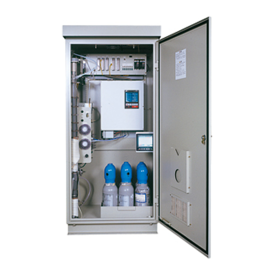
1. oVERVIEW This infrared gas analyzer (ZSU) is composed of infrared gas analyzer unit, oxygen sensor and gas sam- pling equipment. It is capable of accurately and continuously measuring concentration of gases such as NOx, SO , CO, CO and O contained in the flue gas generated from a stationary source such as boiler and dust incinerator. -
Page 13: Outline Diagram
1.1 outline diagram Instrumentation air inlet Sample gas inlet Rc 1/4 Rc 3/8 Air inlet Rc 1/4 4-Wiring port ø34 grommet (Waterproofing with wire through hull fitting is required for outdoor specification analyzer.) When installed outside the standard gas board. 6-Rc 1/4 (Calibration gas inlet) -
Page 14: Sampling System Diagram
1.2 Sampling system diagram (1) 5-component gas sampling system diagram 1 (case of standard type with So first range of 0 to less than 500 ppm) (1) Gas extractor Air inlet Sampling module (7) Flow checker Infrared gas analyzer (10) Atmospheric air 2-way CO,CO solenoid valve... -
Page 15: Wiring Connection Diagram
1.3 Wiring connection diagram INZ-TN5ZSU-E... - Page 16 INZ-TN5ZSU-E...
-
Page 17: Composition And Functions Of Gas Analyzer
1.4 Composition and functions of gas analyzer 1. Gas extractor 2. Gas tube 3. Input power kit 4. Gas analyzer (6) Interface module (1) Gas conditioner TB 1 TB 2 AC100V MAX.2A 主電源 加熱導管 保守SW 保守SW 保守中 保守中 TN 1 TN 2 TN 3 TN 4 TN 5 (5) Solenoid 測定中... - Page 18 Unit name Name Description Collects sample gas efficiently. (A heater and filter are 1. Gas extractor built in.) (1) Heater Prevents clogging of the filter. About 250°C (2) Filter Removes dust. Standard 40 mm Lead tube that feeds sample gas to the gas analyzer 2.
-
Page 19: Composition And Description Of Gas Analyzer
1.4.1 Composition and description of gas analyzer 1. Interface module (4) Select switch during maintenance/measurement (1) I/O Terminals (5) Service receptacle AC100V MAX.2A MAIN POWER HEATING TUBE Maintenance TN 1 TN 2 TN 3 TN 4 TN 5 MAINTENANCE Measurement status Aspirator Extrac-... - Page 20 2. Analyzer unit FUSE 250V T 3.15A POWER SOURCE (1) Power switch Top view (2) Display unit GAS ANALYZER POWER MODE ZERO SPAN ENTER (3) Operation unit Front view Fig. 1-2 Name of unit Name Description Analyzer unit (1) Power switch Power switch for the gas analyzer unit (2) Display unit Displays components and concentration of the measurement...
- Page 21 3. Sampling module (5) Purge flowmeter (8) NO /NO convertor (3) Flow checker (7) Zirconia oxygen sensor (9) Gas dryer (6) Membrane filter (4) Needle valve (2) Solenoid valve for calibration (1) Peltier gas cooler Left side sectional View Flont view Name of unit Name Description...
-
Page 22: Terminal Block
1.4.2 Terminal block (1) List of terminal blocks TB2 (option) At the time of non-insulated output in case a recorder is provided (option) – – Power supply Ch6 output (AO) For internal connection (AC power supply) Ground terminal – Ground for –... - Page 23 (2) Description of terminal block TB2 (option) At the time of non-insulated output Terminal block <TB1> in case a recorder is provided (option) – – Power supply Between 1 – 2 : Terminal block for main power Ch6 output (AO) For internal connection (AC power supply) supply input...
- Page 24 for heating pipe – – Ch2 output (AO) Ch8 output (AO) Temperature input 1 (option) – – – Ch1 output (AO) Ch7 output (AO) Temperature input 2 – (option) M4 screw M3.5 screw Terminal block 1 <TN1> – – Terminal block for analog output –...
- Page 25 Ch3 output (AO) Ch8 output (AO) Ch11 output (AO) changeover input (DI) – – Ch2 remote range Ch2 output (AO) Ch7 output (AO) changeover input (DI) For internal connection – – Ch1 remote range Ch1 output (AO) Ch6 output (AO) changeover input (DI) M3.5 screw M3.5 screw...
- Page 26 output (AO) Ch11 output (AO) changeover input (DI) Ch2 remote range output (AO) changeover input (DI) For internal connection Ch1 remote range output (AO) changeover input (DI) M3.5 screw Terminal block 4 <TN4> Between 1 – 2 : Peak count alarm contact output. range identification CO peak count alarm Maintenance status...
- Page 27 (DI) signal (DO) Average value reset Calibration error Ch2 range identification (DI) contact output (DO) signal (DO) Auto calibration Analyzing block error Ch1 range identification (For atomospheric air remote start signal (DO) contact output (DO) solenoid valve (DO)) (DI) M3.5 screw M3.5 screw Terminal block 5 <TN5>...
-
Page 28: Description Of Display And Operation Panels
1.5 Description of display and operation panels This section describes the display unit and operation panel of the analyzer unit. It also explains the name and description of function on the operation panel. 1.5.1 Name and description of operation panel Fuse FUSE 250V T 3.15A... -
Page 29: Overview Of Display And Operation Panels
1.5.2 overview of display and operation panels * 1) The panel configuration is changed depending on the • Measurement mode display channel. (The measurement mode screen can be viewed by scrolling the arrow key up and down). ZERO ZERO Calibration •... -
Page 30: Outline Of Display Screen
1.5.3 outline of display screen (1) Measurement mode screen (appears when the power is turned oN) The measurement screen depends on the number of components. The following screen configura- tion as shown as an example is for NO, SO , CO , CO and O (output: 12 channel). - Page 31 • O conversion concentration average value: In the Ch (component) and O average value where “ **” is displayed as “ CO” in the conversion concentration value or O con- component display, a value obtained by averaging O centration value in a fixed time is output every 30 seconds. Averaging time can be changed between 1 minute and 59 minutes or 1 hour and 4 hours accord- ing to the average time settings (See “3.7 Parameter setting”).
- Page 32 (3) Contents of measured channel (Ch) The following table gives measurement channels and their contents according to the symbols. Table 1-1 Correspondence between measurement channel and measured value Code symbol Contents 4th digit 5th digit Ch1: NO Ch1: SO Ch1: CO Ch1: NO Ch2: SO Ch1: NO...
-
Page 33: Basic Operation
1.5.4 Basic operation 0 0 . • Measurement mode 0-100 The measurement mode can be displayed 0 0 . 0-100 up to 5 channels in a single screen. If 5 0 0 0 channels or more are to be displayed in a 0-10 vol% 0 0 . -
Page 34: Before Use
2. BEFoRE USE DANGER This unit is not explosion-proof type. Do not use it in a place with explosive gases to prevent explo- sion, fire or other serious accidents. CAUTION • Entrust the installation, movement or re-installation to a specialist or the supplier. A poor installa- tion may cause accidental tipover, shock hazard, fire, injury, etc. -
Page 35: Exhaust And Drain Piping
2.2.2 Exhaust and drain piping (1) Exhaust treatment Exhaust gases containing toxic components from “Exhaust” at the lower part of the side of the locker. Install exhaust pipe in a way that gases are exhausted to an appropriate outdoor place. (2) Drain treatment Discharge the drain through “Drain”... -
Page 36: Standard Gas Cylinder Mounting And Piping
2.2.4 Standard gas cylinder mounting and piping • The number of cylinders depends on the number of components and the type of zero gas. (1) Install pressure regulators at the gas cylinders. Note) For detailed installation, see “4.3.10 How to mount pressure regulator for standard gas cylinder”. -
Page 37: Running Start And Stop
2.3 Running start and stop 2.3.1 Supply of clean water It is necessary to supply clean water into the gas conditioner. Supply tap water to level A and level B respectively, with reference to Fig. 4-1. (See Section “4.1.3 Points of daily check”.) Feeding water in the gas conditioner Remove the head of the gas conditioner (see “4.3.2”) and feed tap water in the gas conditioner to the positions A and B using a water bottle. -
Page 38: Warm-Up Operation
2.3.4 Warm-up operation Turn on the power to each device, and start regular operation. Warm-up is required for taking normal measurement. 100VAC MAX.2A Maintenance Maintenance status Heating tube Main power supply Measurement status LAMP SAMPLING EXTERNAL Aspirator Extractor RECEPT. MODULE SENSOR HEATER 3.2A... -
Page 39: Calibration
2.3.5 Calibration Implementation of zero and span calibration Make sure to implement zero and span calibration of each component before starting normal running. (See “3.2 Calibration setting” for the calibration method). 2.3.6 Shutdown (1) If start/stop is repeated in short periods (batch furnace, for instance) Turn “OFF”... -
Page 40: Setting And Calibration
3. SETTING AND CALIBRATIoN 3.1 Switch of range 3.1.1 Setting of range switch mode MODE Set the range switch mode as follows. (1) Press the key in measurement mode MODE to display the User mode screen. (2) Move the cursor to “Switch Ranges” and press the key. -
Page 41: Manual Range Switch
3.1.2 Manual range switch The range of the measured component can be switched manually as follows. (1) Select “MR” as range switch mode, and then press the key. (2) Move the highlight of the cursor to range selection, and then select a desired range by pressing the or the key. -
Page 42: Calibration Setting
3.2 Calibration setting This mode is used to set calibration concentration and actions. The calibration setting involves cali- bration value, about zero calibration, about calibration range, auto calibration components/range. 3.2.1 Setting of calibration concentration It allows you to set concentrations of the standard gas (zero and span) of each channel used for calibration. - Page 43 (5) In the “Calibration Concentration Se- lection” screen that appears, select any concentration item you want to set by pressing the key. Then press the key, and the selected value is highlighted. Cursor for setting value (6) In the “Calibration Concentration Value Setting”...
-
Page 44: Setting Of Manual Zero Calibration
3.2.2 Setting of manual zero calibration When zero calibration is made manually, set either all measured components should be calibrated simultaneously or each component should be calibrated while selecting one by one. MODE (1) During measurement, press the key to MODE display the User mode. - Page 45 (5) In the “Manual ZERO Calibration Selec- tion” screen that appears, select “at once” or “each” by pressing the or the key. When selecting “at once,” the Ch (components) to be set can be zero-cali- brated at the same time. When selecting “each,”...
-
Page 46: Setting Of Calibration Range
3.2.3 Setting of calibration range This mode is used to set if the range of each Ch (component) at the zero or span calibration (manual calibration or auto calibration) should be calibrated with a single range or 2 ranges. MODE (1) During measurement, press the MODE to display the User mode. - Page 47 (5) On the “calibration range selection” screen that appears, select “both” or “cur- rent” by pressing the or the key. • If “both” is selected, zero or span cali- bration is performed with Range 1 and Range 2 of the selected Ch interlocked. •...
-
Page 48: Setting Of Auto Calibration Component/Range
3.2.4 Setting of auto calibration component/range Select the Ch (component) and the range with which auto calibration is to be performed. The Ch for which “AR” has been selected as range switch mode is calibrated in the range set here even when manual calibration is performed. - Page 49 (5) The cursor next to the range of the se- lected Ch (component) is highlighted. Select the range to be calibrated mainly by pressing the or the key. (6) Then press the key, and calibration is performed in the selected range. To close "Auto Calibration Component/range"...
-
Page 50: Alarm Setting
3.3 Alarm setting 3.3.1 Setting of alarm values The High/Low limit alarm output setting for the measured concentration and power off alarm output (alarm 6 only) setting can be made during measurement. Arbitrary 6 alarm contact outputs can be used. To change alarm setting, set the alarm ON/OFF setting to OFF, and then change the value. - Page 51 (5) After setting, the alarm setting is now Cursor for setting value completed by pressing the key. To close the "Alarm Setting" To close the “Alarm Setting” or to cancel this mode midway, press the key. A previous screen will return. Setting range 0% to 100% FS (Settable in each range).
-
Page 52: Hysteresis Setting
3.3.2 Hysteresis setting To prevent chattering of an alarm output near the alarm setting values, set the value of hysteresis. (1) In the “Alarm Setting” screen that ap- pears, point the cursor to “Hysteresis” by pressing the or the key. Press the key. -
Page 53: Setting Of Auto Calibration
3.4 Setting of auto calibration 3.4.1 Auto calibration Auto calibration is automatically carried out at the time when zero calibration and span calibration are set. Before changing the setting of auto calibration, MODE set the ON/OFF to OFF. (1) During measurement, press the MODE to display the User mode. - Page 54 <Gas flow time> setting (1) Press the key in a state where the cur- sor is placed next to “Flow Time,” and the flow time setting screen shown at right appears. (2) On the flow time setting screen that ap- pears, move the cursor to the gas you want to change the setting by pressing the or the...
- Page 55 Auto calibration status contact output is closed during auto calibration (including Ex. time), and is open in other cases. Example 12:00 Start Time Cycle 350 sec Flow Time Zero 350 sec Ch1 Span 350 sec Ch2 SPan 350 sec Ch3 SPan 300 sec Ch4 SPan 300 sec...
-
Page 56: Forced Run/Stop Of Auto Calibration
3.4.2 Forced run/stop of auto calibration Auto calibration can be performed just once or forcibly stopped while the calibration is performed. [1] Execution of auto calibration (only once) (1) Display the User mode screen. Move the cursor to “Setting of Auto Calibration” by pressing the or the key, and then... - Page 57 [2] Forced stop of auto calibration This mode is used to stop the auto calibration forcedly. (1) In the User mode that is displayed, point the cursor to “Setting of Auto Calibra- tion” by pressing the or the key. Press the key.
- Page 58 “Auto Calibration” screen Example In case where setting the auto calibration components (see Section 3.2.4) to “Ch1: enable” and “Ch2: enable” • Zero calibration ZERO cal. 0-zero100 A message, “Zero cal.” blinks 0 3 . ZERO cal. at Ch1 and Ch2. 0-100 0 0 0 0 0-10...
-
Page 59: Setting Of Auto Zero Calibration
3.5 Setting of auto zero calibration 3.5.1 Auto zero calibration MODE Auto zero calibration is automatically carried out at the time when zero calibration is set. Components for which a calibration is to be made are determined by setting of auto cali- bration component in Section 3.2.4. - Page 60 Auto calibration status contact output is closed during auto zero calibration, and is open in other cases. Example Start time 12:00 Cycle hour Flow time ON/OFF In case where auto zero calibration is carried out at the above setting. Sunday Monday Monday 12:00...
-
Page 61: Forced Run/Stop Of Auto Zero Calibration
3.5.2 Forced run/stop of auto zero calibration Auto zero calibration can be performed just once, or auto zero calibration can be forcibly stopped during calibration. [1] Execution of auto zero calibration (just once) (1) Have the menu mode displayed. Move the cursor to “Setting of Auto Zero Cali- bration”... - Page 62 [2] Forced stop of auto zero calibration This mode is used to cancel the auto zero calibration forcedly. (1) In the Menu Mode that is displayed, point the cursor to “Setting of Auto Zero Cali- bration” by pressing the or the key.
- Page 63 “Auto Zero Calibration” screen Example In case where setting the auto calibration components (see Section 3.2.4) to “Ch1: enable” and “Ch2: enable” • Zero calibration ZERO cal. ZERO cal. 0-100 0 3 . A message, “Zero cal.” blinks ZERO cal. ZERO cal.
-
Page 64: Peak Alarm Setting
3.6 Peak alarm setting When the number of peaks CO concentration exceeds the upper limit value during measurement exceeds the set number, an alarm is provided. The peak alarm and this setting screen appear only when an option is added. MODE (1) Press the key in the Measurement... - Page 65 Setting range Alarm value : 10 to 1000 ppm 5 ppm step (initial value: 500 ppm) Alarm count : 1 to 99 times (initial value: 5 times) Hysteresis : 0 to 20 % of full scale (initial value: 0% of full scale) [% full scale] represents the percentage with the CO range regarded as 100%.
-
Page 66: Parameter Setting
3.7 Parameter setting It allows you to carry out the parameter setting such as time, key lock, etc., as required. Items to be set are as follows: Description of setting items • Current Time : Current year, month, date, day of the week, hour, and minute setting (The display appears in this order.) Note: The clock backup time is 2 days. - Page 67 (4) Enter a numerical value and change the setting by pressing the key, and then move the cursor rightward by press- ing the key. Parameter setting is executed by the entered set value when the key is pressed. To close Parameter Setting screen To close the “Parameter Setting”...
- Page 68 (2) Operation during auto calibration Auto calibration start Auto calibration end Calibration Hold extending time. Output hold Time hold set to the gas flow time (3) External hold Short Open Remote hold Input Output hold (4) Screen display during Holding The “on Hold”...
- Page 69 (6) You can select the value for hold from the value immediately before entering output hold, “cur- rent,” and arbitrary value, “setting.” Follow the procedures shown below to make the setting. 1) Press the key in a state where the cursor is placed next to Hold.
- Page 70 5) On the parameter hold screen that ap- pears, move the cursor next to the Ch (component) you want to make the set- ting by pressing the or the key, and then press the key. 6) The value is highlighted, indicating that the value can be changed.
- Page 71 Average value reset This mode is used to clear all average values O converted average and O average, and restarts averaging. All average values are reset at a time. The indication value and output value is 0 ppm, vol% or so at the time of the reset input (Refer to the average period). Short (hold at least 1.5 sec.) Open Reset input...
- Page 72 Example of average action In case the average period was set to 1 hour. Reset Average value Time 1 hour • Sampling occurs every 30 seconds. • Every 30 seconds, the average for last 1 hour (time setting) is output. •...
-
Page 73: Maintenance Mode
3.8 Maintenance mode This mode is used for check of sensor input values, display of error log files or setting of pass- words, etc. First, enter a password and then use it from the next operation. This mode is displayed by selecting the Maintenance Mode from “3.7 Parameter Setting.”... - Page 74 • Calibration Log screen Description of Calibration Log screen Past calibration history. Sensor input value, concentration value, and the date when zero/span calibration is performed are logged. The 10 newest calibration data is logged by each component. Move the cursor to Clear Calibration Log and press the key, and the calibration log is cleared completely.
- Page 75 • Moisture interference adjustment screen For details of this item, refer to “4.4.2 Optical balance adjustment and moisture interference adjustment of gas analyzer unit.” Description of moisture interference adjustment screen In values on the left side of screen, the moisture interference for each component is already compensated.
- Page 76 • Output adjustment screen Description of output adjustment screen Analog output adjustment screen. Connect the digital multi meter to the output terminal corresponding to the number of OUT to be adjusted, and adjust the value so that 4mA or 0V is output at zero and 20mA or 1V is output at span.
- Page 77 • Other parameter Description of each setting screen Password Set : Set the password used to move from the parameter setting screen to the maintenance mode. Arbitrary 4-digit number can be selected. ref. Value : Set the oxygen concentration reference value at the time of oxygen converted calculation.
- Page 78 (2) Move the cursor to the Ch (component) whose setting is to be changed by pressing the key, and then press the key. (3) Move the cursor to the item whose setting is to be changed by pressing the or the key, and then press the key.
-
Page 79: Calibration
3.9 Calibration ZERO 3.9.1 Zero calibration It is used for zero point adjustment. For zero calibration gas, suited for an application should be used according to “2.2.3 Preparation of standard gas.” (1) Press the key on the Measurement ZERO screen to display the Manual Zero Cali- bration screen. -
Page 80: Span Calibration
3.9.2 Span calibration It is used to perform a span point adjustment. Supply calibration gas with concentration set to the span value to perform the span calibration. For the span calibration gas for the NO , SO , CO , CO analyzer , use the standard gas with a concentration of 90% or more of the range value. -
Page 81: Maintenance And Check
4. MAINTENANCE AND CHECk 4.1 Daily check (Check should be performed daily.) 4.1.1 Check point Gas extractor (2) Gas conditioner TB 1 TB 2 AC100V MAX.2A 主電源 加熱導管 保守SW 保守SW TN 1 TN 2 TN 3 TN 4 TN 5 保守中 保守中 (1) Flow 測定中 蛍光灯 サンプリング 採取器... -
Page 82: Details Of Daily Check Items (For The Standard Version)
4.1.2 Details of daily check items (for the standard version) Check should be performed daily about the following items: Maintenance & check items Maintenance & check procedures (1) Checking the (1) The flow rate measured by the flow checker shall be in the specified range sample flow rate (center range). - Page 83 Maintenance & check items Maintenance & check procedures 4) Check of the 1. Visually check membrane filter for contamination. (1) If the membrane filter is much clogged (See Section 4.3.3.); membrane filter → • If the contamination is excessive, check pre-stage filters such as the gas extractor, wire mesh filter, and mist filter.(See Section 4.3.1 and Section 4.3.2.) Then replace the membrane filter.
-
Page 84: Points Of Daily Check
4.1.3 Points of daily check To gas analyzer Upper chamber Peltier gas cooler A portion Bypass Pressure relief valve B portion Lower chamber Drain H1: Sample negative pressure degree (1) It is satisfactory if H is 50 mm or higher. (2) Check of the extractor filter and the external tube is required, if H is less than 50 mm. -
Page 85: Periodical Check
4.2 Periodical check 4.2.1 Points of periodical check Gas extractor (1) Gas TB 1 TB 2 AC100V conditioner MAX.2A 主電源 加熱導管 保守SW 保守SW 保守中 保守中 TN 1 TN 2 TN 3 TN 4 TN 5 測定中 蛍光灯 サンプリング 採取器 吸引器 コンセント 計 ヒータ 換気扇 モジュール 2.0A 2.0A 3.2A 3.2A 3.2A... -
Page 86: Details Of Periodical Check Items
4.2.2 Details of periodical check items Check should be performed periodically about the following items: Recommended Maintenance & check items Maintenance & check procedures cycle Manual calibration 1. Perform zero/span calibration (See Section 3.9). of analyzer Filling pressure of 1. If filling pressure is 1MPa or less, replace the standard gas cylinder standard gas (3.4L cylinder) (See Section 4.3.10). -
Page 87: Details Of Maintenance Procedure For Sampling Equipment
4.3 Details of maintenance procedure for sampling equipment Refer to “5. SPARE PARTS” for part list. Gas extractor (2) (13) AC100V TB 1 TB 2 MAX.2A Gas conditioner 主電源 加熱導管 保守SW 保守SW TN 1 TN 2 TN 3 TN 4 TN 5 保守中 保守中 測定中 Power 採取器 吸引器... -
Page 88: Maintenance Of Gas Extractor
4.3.1 Maintenance of gas extractor (1) How to remove the wire mesh filter DANGER • Make sure to wear heat-resistant gloves for execution of work. If any work is executed with bare hands or wearing cotton gloves, burn injury may result. •... -
Page 89: How To Replace Gas Conditioner Filter
4.3.2 How to replace gas conditioner filter (1) Loosen the butterfly bolt and extract the head from the container. (2) Then loosen the clamping nut and remove the contaminated gas conditioner filter. (3) Mount a new gas conditioner and a new O-ring (applied with grease), and assemble them in the reverse order of the above. -
Page 90: How To Replace Membrane Filter
4.3.3 How to replace membrane filter (1) Turn OFF the ASPIRATOR switch. (2) Turn the cover of the membrane filter counterclockwise to remove it. (3) After detach the cover and replace the filter by removing internal O-ring. (4) Wipe off dust deposited in the case by clean cloth. Use case to prevent dust from getting into the gas outlet. -
Page 91: How To Replace Valve And Diaphragm Of Diaphragm Type Gas Aspirator
4.3.4 How to replace valve and diaphragm of diaphragm type gas aspirator (1) Turn “OFF” the power to the ASPIRATOR switch on the interface module. Detach the pipes from the inlet and outlet connected to the aspirator. (2) Remove 4 screws to separate cap A and cap B from the valve. (3) Turn the diaphragm counterclockwise with hands and remove it. -
Page 92: How To Replace Peltier Gas Cooler
4.3.5 How to replace peltier gas cooler (1) Turn “OFF” the ASPIRATOR switch on the interface module. (2) Turn “OFF” the SAMPLING MODULE switch on the interface module. (3) Remove the peltier gas cooler tube, the gas inlet/outlet tube (ø8/ø5, ø5/ø3 Viton tube) and drain tubes below the sampling module. -
Page 93: How To Replace Power Fuse
4.3.6 How to replace power fuse If any power fuse is blown out, turn OFF the switch and replace as shown below: (For the type of fuses, see “5.1 Spare parts for 1-year measurement.” AC100V MAX.2A MAINTENANCE MAINTENANCE MAIN POWER HEATING TUBE MEASUREMENT LAMP... -
Page 94: How To Replace Ventilation Filter
4.3.8 How to replace ventilation filter The ventilation filter is located on the backside of the front face door of the gas analyzer. Periodically or when contaminated, remove the ventilation filter, wash it with water, dry it, and then mount it as before. Ventilation filter INZ-TN5ZSU-E... -
Page 95: Maintenance Procedure For No / No Converter
4.3.9 Maintenance procedure for No / No converter /NO converter External terminal block Power 100V AC 50/60Hz How to replace the catalyst CAUTION • To reduce the risk of personal injury from hot converter, take care when replacing catalyst to avoid touching the converter unit. (1) Turn “OFF”... -
Page 96: How To Mount Pressure Regulator For Standard Gas Cylinder
4.3.10 How to mount pressure regulator for standard gas cylinder (1) Before mounting a pressure regulator to the gas cylinder, clean the gas cylinder adapter. Entry of dust into the pressure regulator may result in gas leaks. (2) If packing is not inserted in the mounting nut for the cylinder or it is damaged, replace it with supplied spare one. -
Page 97: Maintenance Of Gas Dryer
4.3.12 Maintenance of gas dryer The gas dryer is used for SO measurement (first range 500 ppm or higher), sludge incineration or for measurement of boiler exhaust gases. Since the gas dryer is free of moving parts and no consumption occurs, it can normally be run without maintenance if the precautions for its use are carefully observed. -
Page 98: Maintenance Of Gas Analyzer Unit
4.4 Maintenance of gas analyzer unit 4.4.1 Replacement of fuse on analyzer unit Fuse holder FUSE 250V T 3.15A POWER SOURCE Power switch Top view of the analyzer unit Note) Prior to the following work, be sure to repair blown down fuse (short, etc), if any. (1) Turn “OFF”... -
Page 99: How To Replace Zirconia O Sensor
4.5 How to replace zirconia o sensor sensor A Mouting screws (× 4) PXR-4 PXR-4 Temperature controller Solid state relay for O sensor Front view View from A Solid state relay sensor Power supply for (SSR) solenoid valve for + −... -
Page 100: Replacement Of Magnetic O Sensor
4.6 Replacement of magnetic o sensor Only fully trained persons can execute the work of this replacement. If such replacement is required, therefore, please contact our adjustment engineer. 4.7 Air tight test When restarting the analyzer that has been shut down for a long period, perform air tight test according to the follow- Gas conditionor ing procedures:... -
Page 101: Spare Parts
5. SPARE PARTS CAUTION • Do not use replacement parts other than recommended ones. Otherwise, it could result in accident or damage to the instrument. • Useless replacement parts for maintenance should be disposed of as non-combustible matter. 5.1 Spare parts for 1-year measurement (1) Designation of type of spare parts 3 4 5 6 7 8 Description... - Page 102 Type or Name Q'ty Application Remarks Sketch Parts number Polyethylene Filter element for TK7H8043P1 For gas conditioner filter roughness: gas conditioner approx. 5 µm with gaskets on both sides O-ring for 8553765 For gas conditioner gas conditioner Gas aspirator TK725417P5 For gas aspirator Viton diaphragm...
-
Page 103: Maintenance Components In A Long-Term
5.2 Maintenance components in a long-term Create a long-term maintenance component procurement plan based on the “Infrared gas analyzer an- nual inspection plan sheet” indicated below. Gas analyzer annual inspection plan sheet • The recommended replacement period of components varies depending on the installation condition. 1) The recommended replacement period is a standard criterion, and it varies depending on the environment of the field, conditions of measuring gas and other factors. - Page 104 Infrared gas analyzer annual inspection plan sheet Recommend- Year Generic With/ Article Component name Q'ty name without replacement Delivered 10th name year year year year year year year year year year year period (year) Infrared light source (semi-sealed) Reference cell Measuring cell Distributing cell Interference filter...
-
Page 105: Troubleshooting
6. TRoUBLESHooTING CAUTION • When you find it difficult to judge failures in spite of referring to the instruction manual, avoid disas- sembling the instrument without consulting our sales agent or service engineers. Otherwise, it may result in electrical shock or personal injury. 6.1 Troubleshooting Problem Check item... - Page 106 Problem Check item Check description Measures The flow rate Pipes and fixed ▪ Check if they are bent or clogged. ▪ Cleaning or replacement of the sample throttles Sampling equipment ▪ Check if a gas is leaked. ▪ Replace the sampling equipment gas is low.
- Page 107 Problem Check item Check description Measures No value is Zero and span ▪ Check if the zero or span deviates. ▪ Zero and span calibration indicated. (Inject a standard gas to check the zero (See Section 3.9 “Calibration”) and span concentrations.) Power supply ▪...
-
Page 108: Troubleshooting For Analyzer Unit
6.2 Troubleshooting for analyzer unit Error message If errors occur, the following contents are displayed. Error display Error contents Probable causes Error No.1 Motor rotation detection signal • Motor rotation is faulty or stopped. faulty • Motor rotation detector circuit is faulty. Error No.4 Zero calibration is not within the •... - Page 109 In case of Error No. 5 and No. 7 • (Error display disappears by pressing key) Calibrated forcedly Calibration is continued. Unless another calibration 9 0 8 0-25 error occurs, calibration is carried out to the end, the 1 3 6 Measurement screen returns.
-
Page 110: Specification
• Measurement principle : • Recorder (option) : NOx, SO , CO and CO ; Ndir type infrared Paperless recorder (Fuji Electric’s type ; Zirconia type, magnetic type PHR) mounted • Measured component and min./max. measurement range : Relief to EDS10-74. - Page 111 • Cubicle structure : Indoor or outdoor installation, of self- standing type, single-swing front door,plate thickness 2.3 mm standard (both cubicle and door) • Other : Six standard gas cylinders (3.4 L) accommodatable Note: Fluctuation in the operation period of 4 hours from the end of warm- up time is within ±2%FS.
- Page 112 3. Performance • Repeatability : ±0.5% of full scale • Zero drift : ±1.0% of full scale or lower/week (±2.0% of full scale/week when the range is less than 200 ppm) Max.±2.0% of full scale/month on O sensor • Span drift : Max.
-
Page 113: Code Symbols
7.2 Code symbols 1 2 3 4 5 6 7 8 10 11 12 15 16 17 18 19 Description Measuring gas component <4th digit> , SO , CO , SO , CO , SO , CO, CO sensor conversion value <5th digit> Without Without Zirconia... - Page 114 1 2 3 4 5 6 7 8 10 11 12 15 16 17 18 19 21 22 23 24 25 26 28 29 30 Description Pipe and cable inlets <21th digit> (Piping port) (Cabling port) (Piping port for external installation of gas cylinder) Top left Top left...
- Page 115 1 2 3 4 5 6 7 8 10 11 12 15 16 17 18 19 21 22 23 24 25 26 28 29 30 Description Gas extractor Tube material Tube length Extraction point temperature <29th digit> Without Without Without With Without Without...
- Page 116 STANDARD GAS CoDE SYMBoLS 1 2 3 4 5 6 7 8 10 11 Z S Y Description measurement first range <4th digit>,ppm Without 1000 2000 5000 measurement first range <5th digit>,ppm Without 1000 2000 5000 CO measurement first range <6th digit>,ppm Without 1000 2000...
-
Page 117: External View
7.3 External view 7.3.1 Gas extractor Rc1/2 Gas outlet Handle exchange filter PL name plate Added for heating tube specifications φ155 Cover Cable hole G1/2 Name plate Terminal box Rc3/4 Flange JIS 5K 65A FF Sampling pipe 20A 4-φ15 φ130 Gas inlet φ155 φ27... -
Page 118: Drain Separator
7.3.2 Drain separator ø10 / ø8 Teflon tube Joint (Teflon) 2-Rc Gas inlet Gas outlet Approx. 96 φ67 2 holes of 9 dia. Approx. 34 ø22 Mass Approx. 0.8 kg Drain Unit: mm 7.3.3 Drain pot Drain port ø60 ø39 hole Mass Approx. - Page 119 International Sales Div Sales Group Gate City Ohsaki, East Tower, 11-2, Osaki 1-chome, Shinagawa-ku, Tokyo 141-0032, Japan http://www.fujielectric.com Phone: 81-3-5435-7280, 7281 Fax: 81-3-5435-7425 http://www.fujielectric.com/products/instruments/...
Need help?
Do you have a question about the ZSU-5 and is the answer not in the manual?
Questions and answers