Table of Contents
Advertisement
Quick Links
Advertisement
Table of Contents

Related Manuals for Fuji Electric ZRE-3


Summary of Contents for Fuji Electric ZRE-3
- Page 1 Instruction Manual NDIR TYPE INFRARED GAS ANALYZAR TYPE: ZRE-3 INZ-TN3ZRE-E...
- Page 2 PREFACE Thank you very much for purchasing Fuji’s Infrared Gas Analyzer (Type: ZRE). injury. Request INZ-TN3ZRE-E...
-
Page 3: Caution On Safety
CAUTION ON SAFETY To operate the analyzer properly, be sure to read “Caution on Safety” carefully. DANGER CAUTION damage. PROHIBITION CAUTION Caution on installation and transport of gas analyzer DANGER CAUTION INZ-TN3ZRE-E... -
Page 4: Caution On Use
Caution on piping Be sure to observe the following precautions while installing DANGER piping. Improper piping may result in gas leakage. If the leaking gas contains a toxic component, serious acci- dents may result. If it contains combustible gases, explosion Caution on wiring CAUTION Caution on use... - Page 5 Caution on use PROHIBITION Caution on maintenance and check DANGER Be sure to observe the following to perform work safely, CAUTION avoiding electric shock or injury. Others CAUTION INZ-TN3ZRE-E...
- Page 6 CONTENTS ........................i ....................ii ......................... v ................................................................................ 5 .................... 5 ......................6 ............... 6 ........................7 ........................ 9 ................9 ..................9 ................9 ................. 9 ................................................................................................................................................................................
- Page 7 ............................................................................................................................................................................................................... 57 .................... 57 ......................................59 ......................59 ............59 ............................................. 65 ..................65 ..............66 ............................................................................75 ....................77 INZ-TN3ZRE-E...
- Page 8 1. OVERVIEW INZ-TN3ZRE-E...
-
Page 9: Name Of Delivered Items And Each Parts
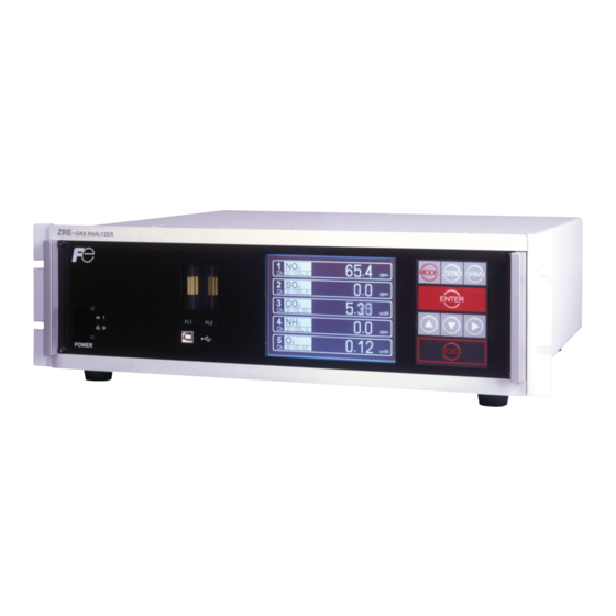
2. NAME OF DELIVERED ITEMS AND EACH PARTS ZRE- GAS ANALYZER MODE ZERO SPAN Analyzer: 1 unit ENTER POWER Standard: IEC127-2 Size: ø5 × 20mm Fuse: 2 pcs Rating: 250V/2A delay type Part No.: TK7L7571P3 25 pin D-sub connector (male) Analog output connector: 1 Part No.: TK7N3059P8 Fixing screws: 2... - Page 10 ③ Flow meter < Front panel > POWER ② Display/operation panel ④ USB connector ① Power switch ⑤ Purge gas inlet ⑪ Communication connector (RS-485) ⑥ Sampling gas inlet (2 systems) ⑫ Analog output connector (A/O) ⑩ External input ⑦ Sampling gas outlet (2 systems) (D-sub25 pin) connector Made in Japan INFRARED GAS ANALYZER <...
- Page 11 ③ Flow meter < Front panel > ② Display/operation panel ④ USB connector ⑤ Purge gas inlet ⑪ Communication connector (RS-485) ⑥ Sampling gas inlet (2 systems) ⑫ Analog output connector (A/O) ⑩ External input ⑦ Sampling gas outlet (2 systems) (D-sub25 pin) connector Made in Japan INFRARED GAS ANALYZER < Rear panel > TYPE ZREABV41-CGCGJ-MCGC1DE-CFYAA 0-200/2000ppm...
-
Page 12: Installation
3. INSTALLATION DANGER CAUTION injury. INZ-TN3ZRE-E... - Page 13 (Unit : mm) Type External dimensions Mounting dimensions Mounting method 19-inch rack mounting 450 or more Support “A” : 57.2 (EIA) or 50 (JIS) “A” : 57.2 (EIA) or 50 (JIS) Panel mounting Panel cutout dimensions Mounting bracket Support INZ-TN3ZRE-E...
- Page 14 CAUTION analyzer. coupling. Purge gas inlet Sampling gas inlet 1 Sampling gas outlet 1 Made in Japan INFRARED GAS ANALYZER TYPE ZREABV41-CGCGJ-MCGC1DE-CFYAA 0-200/2000ppm 0-200/2000ppm 0-1/10% 0-200/2000ppm 0-10/25% OUTPUT DC 4-20mA POWER AC 100V-240V 50/60 Hz 100VA SER.NO. A9P6146T 2009-12 FUSE 250V T 2AL POWER SOURCE Sampling gas inlet 2 For special case only Sampling gas outlet 2 INZ-TN3ZRE-E...
- Page 15 Internal piping diagram Optical unit 2 (IR Unit 2) Optical unit 1 (IR Unit 1) Built-in sensor INLET1 OUTLET1 Sampling gas outlet Sampling cell Note) Sampling gas inlet 2 cells may be used by combination of range. Correspondence of measured components and optical units INZ-TN3ZRE-E...
- Page 16 consider- sensor sensor Zero gas Dry air or more of full scale of full scale INZ-TN3ZRE-E...
- Page 17 (1) Gas extractor ZRE unit (11) NO (7) Membrane 10/ 8 converter filter Teflon tube (4) Gas aspirator 2-way (8) Flowmeter Infrared gas solenoid (2) Mist filter analyzer valve main frame (O Electronic gas cooler ZERO NO Solenoid valve Pressure (3) Safety reducing valve drain...
- Page 18 CAUTION DANGER External input connector (A/I) Communication connector (RS-485) Analog output connector (A/O) Made in Japan INFRARED GAS ANALYZER TYPE ZREABV41-CGCGJ-MCGC1DE-CFYAA 0-200/2000ppm 0-200/2000ppm 0-1/10% 0-200/2000ppm 0-10/25% OUTPUT DC 4-20mA POWER AC 100V-240V 50/60 Hz 100VA SER.NO. A9P6146T 2009-12 FUSE 250V T 2AL POWER SOURCE Power terminal block Digital input/output connector (DIO 1 to 3) INZ-TN3ZRE-E...
- Page 19 3 2 1 Attached ferrite core AC100 to 240V Earth cable CAUTION <In case of UL model> Power inlet Grounding 2-pole plug When noise source is in the vicinity Main unit power supply Varistor or spark killer Install (connect) near the source. Noise generating source...
- Page 20 < Analog output > A/O connector AO1+ AO1- AO2+ AO2- AO3+ D-sub 25-pin female AO3- AO4+ Note) Display Ch number is same AO4- as the AO number under AO5+ AO5- standard specifications. AO6+ AO6- AO7+ AO7- AO8+ AO8- AO9+ AO9- AO10+ AO10- AO11+...
- Page 21 (3) O < External input > A/I connector (O sensor input) order. full scale analyzer is Turn To O sensor − Solder the signal cable to the terminal. INZ-TN3ZRE-E...
- Page 22 digital input/output connector (DIO1 to 3) < Digital input/output > Connector for DIO 1 to 3 (option) DIO1 DIO2 DIO3 connector connector connector DI1+ DI4+ DI7+ DI1- DI4- DI7- Digital input DI2+ DI5+ DI8+ OFF : 0V DI2- DI5- DI8- ON : 12 to 24V DC DI3+ DI6+...
- Page 23 RS-485/USB connector < RS-485 connector > (GND) RT D+ RT D- D-sub 9-pin female 1) Manual calibration (See “Item 6.8 Calibration”.) (When the analyzer has auto calibration function.) INZ-TN3ZRE-E...
- Page 24 2) In case of automatic calibration (example shown in Item 6.4.1, Automatic calibration settings) Automatic Ch1 span Ch3 span calibration Ch5 span calibration calibration start calibration Ch4 span Ch2 span Zero calibration calibration calibration Zero gas Zero calibration output 350 s Ch1 span calibration output Ch1 span gas 350 s...
-
Page 25: Operation
4. OPERATION Note) When in warm-up, the concentration reading may be beyond. upper limit of range. But, it is not an error. INZ-TN3ZRE-E... -
Page 26: Description Of Display And Operation Panels
5. DESCRIPTION OF DISPLAY AND OPERATION PANELS Display unit POWER Operation panel ⑦ ZERO key ① MODE key ⑧ SPAN key MODE ZERO SPAN ⑥ ENT key ENTER ③ UP key ② SIDE key ⑤ ESC key ④ DOWN key Fig. - Page 27 Measurement mode * 1) The panel configuration is changed depending on the display channel. (The measurement mode screen can be viewed by scrolling the arrow key up and down). ZERO ZERO Calibration Measurement mode SPAN Calibration SPAN Measurement mode MODE MODE Selection of items User mode...
- Page 28 ① ② ① ② 0-200 0-200 0-200 0-200 0.0 0 Scroll vol% 0-20 0-200 0-200 0-200 0.0 0 vol% vol% 0-25 vol% 0-25 ③ ④ ③ ⑤ Fig. 5-3 ① ② ③ Range display ④ ⑤ INZ-TN3ZRE-E...
- Page 29 Instantaneous value and concentration value: correction concentration values: correction concentration average value: aver- Message display area Status display area display area Cursor Fig. 5-4 INZ-TN3ZRE-E...
- Page 30 Code symbol 6th digit 7th digit 21st digit Display/output contents 1 to 3 Ch1:O Ch1:NO Ch1:SO Ch1:CO Ch1:CO Ch1:CH Ch1:NO, Ch2:SO Ch1:NO, Ch2:CO Ch1:CO , Ch2:CO Ch1:CH , Ch2:CO Ch1:CO , Ch2:CH Ch1:NO, Ch2:SO , Ch3:CO Ch1:CO , Ch2:CO, Ch3:CH Ch1:NO, Ch2:SO , Ch3:CO , Ch4:CO...
- Page 31 0 0 . 0-200 0 0 . 0-200 0 0 0 0-10 vol% 0 0 . 0-200 0 0 0 0-25 vol% ZERO 0 0 0 0-25 vol% 0 0 . See 6.9.1. 0-200 . 0 0 0-10 0 0 . See 6.9.2.
-
Page 32: Setting And Calibration
6. SETTING AND CALIBRATION MODE MODE key. key. Description of setting MR: Select a desired range on this screen. RR: Select a desired range according to the remote range switch contact input. AR: Automatically switched from Range 1 to Range 2 when the measured concen- tration exceeds 90% of Range 1. - Page 33 key. key. (The range.) Note) If “RR” or “AR” is selected as range switch mode, this operation cannot be performed. The range for O correction value, correction average value, and average value is automatically switched if corresponding instanta- neous value range is switched. (Same as for “RR”...
- Page 34 key. value. INZ-TN3ZRE-E...
- Page 35 Cursor for setting value Note) Enter settings that correspond to each range. If zirconia type is used as O (when air is used), and select the con- centration listed on the cylinder if the air contained in a cylinder is used. To close the setting To close the calibration concentration value setting process or cancel this mode midway,...
- Page 36 key. To close the setting To close the manual zero calibration setting or to cancel this mode midway, press the ESC key. A previous screen will return. Example Whether “each” or “at once” can be determined for each Ch (component). INZ-TN3ZRE-E...
- Page 37 Manual Calibration screen INZ-TN3ZRE-E...
- Page 38 key. To close “Setting of Calibration Range” To close “Setting of Calibration Range” or to cancel this mode midway, press the key. A previous screen will return. Example Range 1: 0 to 200 ppm both Range 2: 0 to 2000 ppm Range 1: 0 to 200 ppm current Range 2: 0 to 2000 ppm...
- Page 39 key. performed. “Auto Calibration Component/range” setting Auto calibration and the manual calibration of the component with which “AR” has been selected as range switch mode are performed in the range selected here. In this case, once the calibration is started, the range is automatically switched, and on completion of the calibration, the original range is resumed.
- Page 40 To close the setting Press the key to exit automatic calibration component/range setting, and the previous screen appears. Operation by setting Auto calibration is performed under the following rules. 1. Zero calibration is performed at the same time, for the Ch (component) with which “enable” is selected at the time of auto calibration and auto zero calibration.
-
Page 41: Setting Range
key. key. key. Note Set the values so that H-limit value > L-limit value and that (H-limit value - L-limit value) > hysteresis. When “0” is set, the alarm operation is not performed. Cursor for setting value key. To close the "Alarm Setting" To close the “Alarm Setting”... - Page 42 Description of setting items The alarm contact assigned the same number as the alarm is operated accordingly. Channel: Channel setting targeted for issuance of alarm. One Ch No. can be selected for multiple alarms. H-Limit value: Sets the high limit value (concentration) of alarm. L-Limit value: Sets the low limit value (concentration) of alarm.
- Page 43 To close "Hysteresis Setting" To close the “Hysteresis Setting” or cancel the mode midway, press the key. A previous screen will return. Setting range 0 to 20% of full scale Note [% full scale (FS)] represents the percentage with the width of the range of each compo- The hysteresis is common to all alarms nent regarded as 100%.
- Page 44 key. Press the key, and date and time are Description of setting items displayed alternately. To close "Setting of Auto calibration" To close the "Setting of Auto calibration" or cancel this mode midway, press the key. A previous screen will return. INZ-TN3ZRE-E...
- Page 45 key. key. key. Note) Only the Chs used are displayed on this screen. The Ex. time is the out- put signal hold extension time after the completion of calibration. It is valid only when the hold setting is set to “ON.” The Ex. time set here is also the hold extension time at the time of manual calibration.
- Page 46 cases. Example 12:00 Start Time Cycle 350 sec Flow Time Zero 350 sec Ch1 Span 350 sec Ch2 Span 350 sec Ch3 Span 300 sec Ch4 Span 300 sec Ch5 Span 300 sec EX. time ON/OFF In case where auto calibration is carried out at the above setting. Sunday Monday Tuesday...
- Page 47 key. key. INZ-TN3ZRE-E...
- Page 48 “Auto Calibration” screen Example 0 3 . 0 0 0 0 0 0 . 2 1 0 2 9 0 8 0 0 . 0 0 0 0 0 . 0 0 0 9 5 0 . 0 0 0 0 0 .
- Page 49 key. Press the key, and Description of setting items date and time are displayed alternately. To close "setting of Auto Zero Calibration" To close the “Setting of Auto Zero Calibration” or cancel this mode midway, press the key. A previous screen will return. INZ-TN3ZRE-E...
- Page 50 Example Start time 12:00 Cycle hour Flow time ON/OFF In case where auto zero calibration is carried out at the above setting. Sunday Monday Monday 12:00 0:00 12:00 Cycle : Auto zero calibration Replace- Zero ment calibration time 300sec 300sec Gas replacement time after calibration is the same as the flow time.
- Page 51 key. key. cancel. key. key. INZ-TN3ZRE-E...
- Page 52 “Auto Zero Calibration” screen Example 0 3 . 0 0 0 0 0 . 2 1 0 2 Caution During auto zero calibration, any key operation is not permitted other than operations such as key lock ON/OFF and “Auto Zero Calibration Stop.” When the key lock is set at ON, even the “Auto Zero Calibration Stop”...
- Page 53 Description of setting items key. To close Parameter Setting screen To close the “Parameter Setting” screen or cancel this mode midway, press the key. A previous screen will return. INZ-TN3ZRE-E...
-
Page 54: Manual Calibration
Setting Range Manual calibration ZERO Press the key to flow gas. SPAN To execute calibration, press the key. Calibration Hold extending time Output hold Time set to gas flow time (See Item 6.4 Auto Calibration.) Auto calibration Auto calibration start Auto calibration end Calibration Hold extending time. - Page 55 key. key. INZ-TN3ZRE-E...
- Page 56 key. key. Meaning of setting The setting is expressed in % against the range for both ranges. When 0 to 1000 ppm is selected as the range, for example, if 10% FS is selected as hold setting, the output equivalent to 100 ppm is output and held irrespective of the measure- ment value at that time.
- Page 57 average. With input (hold at least 1.5 sec.) Without input Reset input So long as with input, resetting lasts. At the edge of changing from “with input” to “without input,” the average action restarts. In case the average period was set to 1 hour. Reset INZ-TN3ZRE-E...
- Page 58 off. key. INZ-TN3ZRE-E...
- Page 59 key. played. Note) “To Factory Mode” is used for our service engineers only. each screen. Description of Error Log screen Error history. 14 newest errors are logged. For error number, date and time (year, month, day, period) of occurrence, channel and other details of error, refer to Item 8.1 Error message.
- Page 60 Description of Calibration Log screen Past calibration history. Sensor input value, concentration value, and the date when zero/span calibration is performed are logged. The 10 newest calibration data is logged by each component. Move the cursor to Clear Calibration Log and press the key, and the calibration log is cleared completely.
- Page 61 Description of output adjustment screen Analog output adjustment screen. Connect the digital multi meter to the output terminal corresponding to the number of OUT to be adjusted, and adjust the value so that 4mA or 0V is output at zero and 20mA or 1V is output at span.
- Page 62 Description of each setting screen Password Set : Set the password used to move from the parameter setting screen to the maintenance mode. Arbitrary 4-digit number can be selected. ref. Value : Set the oxygen concentration reference value at the time of oxygen correction calculation.
- Page 63 key. key. key. Settable range The value for range 1 and range 2 must fall within the range from the MIN and the MAX range (including the MIN and the MAX range), and at the same time range 1 must be smaller than range 2.
- Page 64 ZERO ZERO key. Caution For the Ch (components) that is set to “both” in the “Zero Calibration” of the Calibration Setting mode, zero calibration is also carried out at the same time. Note: For the Ch (component) for which “AR” is selected in “6.1.1 Setting range switch mode,”...
- Page 65 sensor. SPAN SPAN key and press Caution When “both” from “Calibration Range” of the Calibration Setting mode is set, span calibra- tion is performed together with 2 Ranges. Note: For the Ch (component) for which “AR” is selected in “6.1.1 Setting range switch mode,”...
-
Page 66: Maintenance
7. MAINTENANCE Table 7.1 Maintenance and check table Remedy sampling cell. higherd. repair. analyzer analyzer Gas analyzer Regardless of any phenomena INZ-TN3ZRE-E... - Page 67 (1) How to remove pipe cell (See Fig. 7-1) panel). Sampling cell Screw INZ-TN3ZRE-E...
- Page 68 Name Screw (for fixing the light source unit) Screw (for fixing the detector) Screw (for fixing the gas filter) Base plate Light source unit Screw (for fixing the support) Screw (for fixing the cell retainer) Gas filter Filter Support Cell retainer Pipe cell O-ring Infrared transmission window...
- Page 69 (2) How to remove block cell (See Fig. 7-2) Note) The O-ring (No. 9) is placed between the window holder and cell. Take care about the O-ring position. With 2-component analyzer, install 2-component detector last. Take care so that no space is left between the 1-component and 2-component detec- tors.
- Page 70 Name Screw (for fixing the light source unit) Filter Screw (for fixing the detector) Base plate Light source unit Screw (for fixing the block cell) Block cell Infrared transmission window (window holder) O-ring Screw (for fixing the measuring unit) Gas filter Detector INZ-TN3ZRE-E...
- Page 71 How to remove measuring unit (See Fig. 7-3) Note) Special care should be taken when assembling or disassembling the measuring cell to avoid the application of force to the detector pipe or infrared ray light source unit pipe. If the pipe is deformed or damaged by excessive force, there is a danger of gas leak, thus resulting in misoperation.
- Page 72 dow roughly. hol. INZ-TN3ZRE-E...
- Page 73 gas. INZ-TN3ZRE-E...
- Page 74 INZ-TN3ZRE-E...
-
Page 75: Error Message
8. ERROR MESSAGE Error display Error contents Probable causes Error No.1 Light source/motor rotation is Infrared light source is faulty. faulty. Sector motor is not properly run or is stopped. Amplifier circuit is faulty. Error No.2 Detector failure Detector voltage circuit is faulty. Amplifier circuit is faulty. - Page 76 Screen display and operation at the occurrence of error 0 0 8 Error No.9 0-25 1 3 6 0-200 0 0 0 0 0-10 vol% 0-200 2 1 0 0 0-25 vol% Calibrated forcedly Calibration is continued. Unless another calibration 9 0 8 0-25 error occurs, calibration is carried out to the end, the...
- Page 77 nance mode. Error log screen Date and time when an error occurred. Component with which the error occurred. Errors that occurred Deletion of error history INZ-TN3ZRE-E...
-
Page 78: Standard Specifications
9. SPECIFICATIONS Analog input signal: For signal input from externally installed sensor. Standard Specifi cations Signal requirement; Principle of measurement: Signal from Fuji’s Zirconia O sensor NO, SO , CO , CO, CH (TYPE: ZFK7) Non-dispersion infrared-ray absorption sensor method Single light source and single beams feature is effective when an O sensor... -
Page 79: Standard Functions
Standard Functions Output signal holding: Output signals are held during manual and auto calibrations by activation of holding (turning “ON” its setting). The output to be held are the ones just before start calibration mode or setting in auto calibration is set. value. - Page 80 correction: Correction of measured NO, SO and CO Response time (for 90% FS response) : gas concentrations into values at refer- ence O concentration Correction formula: × Cs Gas replacement time depends on the number of measuring components,and C : Sample gas concentration after O measuring range.
-
Page 81: Installation Requirements
Installation Requirements or cover should be prepared for protection.) EU Directive Compliance LVD (2014/35/EU) EMC (2014/30/EU) RoHS (2011/65/EU) INZ-TN3ZRE-E... - Page 82 Digit 1 2 3 4 5 6 7 9 10 11 12 13 14 15 16 17 18 19 20 21 22 23 24 25 26 note Z R E A Digit Description <Housing> Fuji Standard 19 inch housing <Mounting> 19-inch rack mounting type EIA conformity 19-inch rack mounting type JiS conformity Panel mounting type...
- Page 83 Digit 1 2 3 4 5 6 7 9 10 11 12 13 14 15 16 17 18 19 20 21 22 23 24 25 26 Z R E A Description note Digit <Unit> ppm, % mg/m , g/m note7 <Adjustment>...
- Page 84 <Top view> Power Switch <Front view> POWER Digital input/output connector (DIO 1 to 3) Analog output connector (A/O) Communication Purge gas inlet Rc 1 /4 or NPT 1 /4 connector (RS485) 1 /4 1 /4 Sample gas inlet Rc or NPT Analog external input Sample gas outlet Rc 1 /4...
- Page 85 Instrumentation & Sensors Planning Dept. 1, Fuji-machi, Hino-city, Tokyo 191-8502, Japan http://www.fujielectric.com Phone: +81-42-514-8930 Fax: +81-42-583-8275 http://www.fujielectric.com/products/instruments/...
Need help?
Do you have a question about the ZRE-3 and is the answer not in the manual?
Questions and answers