Table of Contents
Advertisement
Quick Links
Advertisement
Table of Contents

Related Manuals for Terex Genie GTH-4013


Summary of Contents for Terex Genie GTH-4013
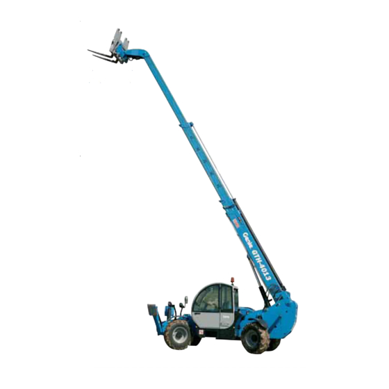
- Page 1 Part N. 57.0007.0200 Rev. 0 01/2006 English Operator's manual From serial n. 14518 Edition To serial n. 19104 GTH-4013 CAUTION: THOROUGHLY READ AND UNDERSTAND THIS HANDBOOK BEFORE OPERATING THE MACHINE CAUTION: KEEP THIS HANDBOOK IN THE MACHINE AT ALL TIMES...
- Page 3 TECHNICAL SERVICES Genie Scandinavia Genie Mexico City Genie Malaysia Phone +46 31 575100 Phone +52 55 5666 5242 Phone +65 98 480 775 +46 31 579020 +52 55 5666 3241 +65 67 533 544 Genie France Genie North America Genie Japan Phone +33 (0)2 37 26 09 99 Phone...
- Page 4 REVISED PAGE LIST Revision Revised Issued date pages Notes...
- Page 5 Handler with telescopic boom GTH-4013 INTRODUCTION ■ INTRODUCTION Sections are subdivided into chapters and paragraphs that are numbered progressively. This manual provides information for a safe and proper operation and maintenance of the machine. The quickest way to look for information is the reference to the general index or the titles of the single chapters STRICTLY COMPLY WITH THE INSTRUCTIONS and paragraphs that represent keys for an easy...
- Page 6 Handler with telescopic boom GTH-4013 INTRODUCTION ■ SYMBOLS CAUTION When using the machine, operators could have to face some situations requiring special care and particular Yellow with safety alert symbol: used to indicate a knowledge. potentially hazardous situation which, if not avoided, may result in minor or moderate injury.
- Page 7 Handler with telescopic boom GTH-4013 GENERAL INDEX GENERAL INDEX GENERAL INFORMATION Sect. SAFETY PRECAUTIONS Sect. OPERATING INSTRUCTIONS Sect. MAINTENANCE Sect. TROUBLESHOOTING Sect. OPTIONAL ATTACHMENTS Sect. TABLES AND DOCUMENTS ENCLOSED Sect. Page Document 57.0007.0200 - 01/2006...
- Page 8 Handler with telescopic boom GTH-4013 INTENTIONALLY BLANK PAGE Page Document 57.0007.0200 - 01/2006...
-
Page 9: Table Of Contents
Handler with telescopic boom GTH-4013 GENERAL INFORMATION Section GENERAL INFORMATION TABLE OF CONTENTS CONVENTIONAL REFERENCES ................A-1.1 Machine position ......................A-1.2 Labels and warning plates applied on the machine ........... A-1.3 Explanation of the different symbols used on the machine ........A-10 MACHINE IDENTIFICATION .................. -
Page 10: Conventional References
Handler with telescopic boom GTH-4013 GENERAL INFORMATION A-1 CONVENTIONAL REFERENCES ■ A-1.1 MACHINE POSITION Conventionally the machine should be considered positioned as shown in the figure. This convention is necessary to make any reference of this handbook to different machine parts (front, rear, etc.) clear and unmistakable. -
Page 11: A-1.2 Labels And Warning Plates Applied On The Machine
Handler with telescopic boom GTH-4013 GENERAL INFORMATION ■ A-1.2 LABELS AND WARNING PLATES IMPORTANT APPLIED ON THE MACHINE This paragraph lists the labels and warning plates The familiarisation with these labels is never a waste of time. normally applied on standard machines or on special Make sure they are easy to read. - Page 12 Handler with telescopic boom GTH-4013 GENERAL INFORMATION 09.4618.0361 09.4618.0661 09.4616.0068 09.4618.0663 09.4618.0361 09.4618.0516 09.4618.0230 09.4618.0230 09.4618.0212 09.4618.0010 09.4618.0547 09.4618.0061 09.4618.0662 09.4618.0230 09.4618.0243 09.4618.0547 09.4618.0061 Page Document 57.0007.0200 - 01/2006...
- Page 13 Handler with telescopic boom GTH-4013 GENERAL INFORMATION Decal Code Description 09.4618.0022 Keep out of the working range of the machine. KEEP OUT OF When the machine is running, entering the working WORKING RANGE range of the machine is prohibited. 09.4618.0212 Keep out of the working range of the machine.
- Page 14 Handler with telescopic boom GTH-4013 GENERAL INFORMATION Decal Code Description 09.4618.0010 Do not open while engine is running. VIETATO APRIRE CON MOTORE IN MOTO DO NOT OPEN WHILE ENGINE IS RUNNING Do not open the engine bonnet when engine is N'OUVRIR QU'A L'ARRET DU MOTEUR ÖFFNEN NUR BEI STILLSTEHENDEM MOTOR running, since this may result in serious injury due to...
- Page 15 Presence of moving parts. Use extreme caution when moving the outriggers. 09.4618.0547 Tyre inflation sticker. (standard) Placed near the wheels, this label shows the recommended tyre inflation pressure. 09.4618.0061 (optional) 09.4618.0241 "GENIE" sticker. 09.4618.0242 09.4618.0243 GTH-4013 09.4618.0661 "GENIE GTH-4013" sticker. Page Document 57.0007.0200 - 01/2006...
- Page 16 Handler with telescopic boom GTH-4013 GENERAL INFORMATION Decal Code Description Kg 4000 09.4616.0040 Max capacity. Indicates the maximum capacity of the machine. 09.4616.0068 Machine data plate. The identification plate contains the main identification data of the machine. TEREXLIFT srl - ZONA INDUSTRIALE - 06019 UMBERTIDE (PG) - ITALY Tel.
- Page 17 Caution: accumulator under pressure. ATTENZIONE! CAUTION! IN ATTESA DA RECIPIENTE IN PRESSIONE TEREX HIGH PRESSURE ACCUMULATOR 09.4618.0673 Emergency controls. Reminds the operator the correct procedure for the manual operation of the main valve in an emergency. It also shows the controls and the relevant controlled movements of all the levers of the main valve.
-
Page 18: A-1.3 Explanation Of The Different Symbols Used On The Machine
Handler with telescopic boom GTH-4013 GENERAL INFORMATION ■ A-1.3 EXPLANATION OF THE DIFFERENT IMPORTANT SYMBOLS USED ON THE MACHINE This paragraph illustrates those symbols that are Spend the necessary time to become familiar with these symbols and to learn their meaning. normally applied on the main control devices and instruments of a standard machine, and those that can be applied on accessories or special attachments. - Page 19 Handler with telescopic boom GTH-4013 GENERAL INFORMATION Symbol Description Symbol Description Lifting point Right outrigger up Left outrigger down Emergency pump Left outrigger up Sway right Sway left Machine sway control Cab controls Platform controls Road setting Oil filter clogged Air filter clogged Speed selector switch speed engaged...
-
Page 20: Machine Identification
Handler with telescopic boom GTH-4013 GENERAL INFORMATION A-2 MACHINE IDENTIFICATION IMPORTANT Check that the operator handbook refers to the delivered machine. When asking for information or technical assistance, always specify model, type and serial number of the machine. ■ A-2.1 TEREXLIFT srl - ZONA INDUSTRIALE - 06019 UMBERTIDE (PG) - ITALY MACHINE MODEL AND TYPE Tel. -
Page 21: A-2.4 Ce Marking
Handler with telescopic boom GTH-4013 GENERAL INFORMATION ■ A-2.5 Road traffic data plate CHASSIS SERIAL NUMBER The road traffic data plate is installed on the front The chassis serial number is punched on the front left right side of the chassis (only on machines destined for part of the chassis side member the Italian market). -
Page 22: Allowed Use
Handler with telescopic boom GTH-4013 GENERAL INFORMATION ■ A-3.2 A-3 ALLOWED USE IMPROPER USE Improper use means a utilisation of the handler ■ A-3.1 following working criteria that do not comply with the ALLOWED USE instructions of this manual, and that, in general, may The handlers have been designed and manufactured result in risks for both operators and bystanders. -
Page 23: A-3.4 Applicable Standards
Handler with telescopic boom GTH-4013 GENERAL INFORMATION ■ A-3.4 APPLICABLE STANDARDS EN 50081-1: 1997 Electromagnetic compatibility – Generic requirements on emissions - Part 1 For the operator’s safety, the following standards were EN 50082-1: 1997 Electromagnetic compatibility – Generic obeyed during the risk assessment of the handler fitted requirements on immunity - Part 1 with telescopic boom: EN 60204-1:1998 Safety of machinery... -
Page 24: A-3.5 Safety Devices
Handler with telescopic boom GTH-4013 GENERAL INFORMATION ■ A-3.5 SAFETY DEVICES • Limit switch on the outriggers When the outriggers are lowered to the ground: • Load limiting device. It consists of a load cell fitted the overload warning system changes the meter to the rear axle and a display installed in the driving scale place. - Page 25 Handler with telescopic boom GTH-4013 GENERAL INFORMATION • Safety pushbutton on joystick (dead man button). This button must be pressed and held down while executing a function with the control lever. If the button is released, the movement in progress will be blocked.
- Page 26 Handler with telescopic boom GTH-4013 GENERAL INFORMATION E Block valve on attachment pitching cylinder F Block valve on the outrigger cylinder G Block valve on the rear axle block cylinder H Block valve on machine sway cylinders A-18 Page Document 57.0007.0200 - 01/2006...
- Page 27 Handler with telescopic boom GTH-4013 GENERAL INFORMATION • Limit switches and safety switches: L Limit switch fitted to the left side of the boom that, through a jack fixed to the chassis, blocks the rear axle when the boom inclination is above 40°.
-
Page 28: General Description
Handler with telescopic boom GTH-4013 GENERAL INFORMATION A-4 GENERAL DESCRIPTION ■ A-4.1 LIST OF THE MAIN COMPONENTS 1 - 3 boom section 2 - 2 boom section 3 - 1 boom section 5 - Rear view mirror, left side 6 - Chassis 7 - Forks 8 - Attachment holding frame 9 - Left sway cylinder... -
Page 29: A-4.2 Description Of The Main Components
Handler with telescopic boom GTH-4013 GENERAL INFORMATION ■ A-4.2 DESCRIPTION OF THE MAIN Tyres COMPONENTS The machine is equipped with tyres suitably sized for the maximum load allowed on the handler. Chassis When worn, they shall be replaced with new ones Made of high tensile steel to improve robustness and having the same dimensions and loading capacity. -
Page 30: Technical Data And Performance
Handler with telescopic boom GTH-4013 GENERAL INFORMATION A-5 TECHNICAL DATA AND PERFORMANCE ■ A-5.1 MAIN DIMENSIONS GTH-4013 A Overall height ......................mm 2425 B Height to the steering wheel ..................mm 1600 C Overall width ......................mm 2330 D Cab width ........................mm E Track ......................... -
Page 31: Payload And Reach
Handler with telescopic boom GTH-4013 GENERAL INFORMATION ■ A-5.5 PAYLOAD AND REACH GTH-4013 - Max lifting height: with outriggers ......................mm 13000 without outriggers ..................... mm 12810 - Reach at max height without outriggers ..............mm - Max reach forward with outriggers ................mm 9020 - Attachment holding plate rotation .................. -
Page 32: Lifetime
Handler with telescopic boom GTH-4013 GENERAL INFORMATION A-7 ITEMS SUPPLIED A-6 LIFETIME Following items are supplied together with the The lifetime of the machine is 10000 hours provided machine: all checks, service jobs and overhauls are done at the times scheduled. This lifetime should be halved if the handler is used Description GTH-4013... - Page 33 Handler with telescopic boom GTH-4013 SAFETY PRECAUTIONS Section SAFETY PRECAUTIONS TABLE OF CONTENTS GENERAL REMARKS ....................PREREQUISITES OF THE PERSONNEL IN CHARGE ..........B-2.1 Requisites of the machine operators ................. B-2.2 Requisites of the servicemen ..................B-2.3 Working clothes ......................B-2.4 Personal protective equipment ..................
-
Page 34: General Remarks
Handler with telescopic boom GTH-4013 SAFETY PRECAUTIONS B-1 GENERAL REMARKS DANGER Not observing the instructions Most accidents occurring while working, repairing or and safety rules in this manual maintaining machines, are caused by not complying may result in death or serious with the basic safety precautions. -
Page 35: B-2.1 Requisites Of The Machine Operators
Handler with telescopic boom GTH-4013 SAFETY PRECAUTIONS ■ B-2.2 REQUISITES OF THE SERVICEMEN REQUISITES The personnel charged with the machine maintenance PERSONNEL IN CHARGE shall be qualified, specialised in the maintenance of earth-moving machines, and shall have the following ■ B-2.1 REQUISITES MACHINE prerequisites:... -
Page 36: B-2.3 Working Clothes
Handler with telescopic boom GTH-4013 SAFETY PRECAUTIONS ■ B-2.3 WORKING CLOTHES B-3 SAFETY PRECAUTIONS During work, but especially when maintaining or repairing the machine, operators must wear suitable ■ B-3.1 HAZARDS ON THE JOBSITE protective clothing: Always take into account the features of the job site •... -
Page 37: B-3.2 Operation Or Maintenance Hazards
Handler with telescopic boom GTH-4013 SAFETY PRECAUTIONS ■ B-3.2 OPERATION OR MAINTENANCE HAZARDS DANGER Before any operation, following precautions should be taken: Make sure the machine (wheels and stabilisers) • First of all, make sure that the maintenance rests on a firm ground to prevent hazardous interventions have been carried out with care unstable conditions. - Page 38 Handler with telescopic boom GTH-4013 SAFETY PRECAUTIONS • When entering/leaving the cab or other raised • Except for maintenance purposes, do not remove parts, always face the machine; never turn the safety devices, shields, protection cases, etc. back. Should their removal be necessary, stop the engine, remove them with the greatest care and always remember to refit them before starting the engine and using the machine again.
-
Page 39: B-3.3 Machine Operation Hazards
Handler with telescopic boom GTH-4013 SAFETY PRECAUTIONS ■ B-3.4 • Do not empty catalytic mufflers or other vessels DAMAGED COMPONENT HAZARDS containing burning materials without taking the • Do not use battery chargers or batteries with a necessary precautions. voltage above 12V to start the engine. •... -
Page 40: B-3.6 Damaged Machine Hazards
Handler with telescopic boom GTH-4013 SAFETY PRECAUTIONS ■ B-3.6 ■ DAMAGED MACHINE HAZARDS B-4 SAFETY DEVICES • Do not use a damaged or defective machine. • Do a thorough pre-operation inspection of the DANGER machine and test all functions before each work shift. - Page 41 Handler with telescopic boom GTH-4013 OPERATING INSTRUCTIONS Section OPERATING INSTRUCTIONS TABLE OF CONTENTS PRE-OPERATION INSPECTION .... C-2 SETUP ..........C-26 ENTERING THE MACHINE ....C-4 C-4.1 Before starting the engine ....C-26 C-2.1 Entering the cab ........C-4 C-4.1.1 Checks at the machine start-up ... C-26 C-2.1.1 Emergency exit-way .......
- Page 42 Handler with telescopic boom GTH-4013 OPERATING INSTRUCTIONS Fundamentals INTRODUCTION It is the operator responsibility to perform a pre- This section provides the operator a practical guide operation inspection and routine maintenance. for the gradual learning of the machine use. The operator should get into the driving cab and carry Pre-operation inspection means a visual inspection out the preliminary adjustments, then memorise the performed by the operator prior to each work shift.
-
Page 43: Pre-Operation Inspection
Handler with telescopic boom GTH-4013 OPERATING INSTRUCTIONS Check the entire machine for: Pre-operation inspection • cracks on welds or structural components ☛ Make sure the operator’s manuals are intact, legible • dents or damage to the machine. and placed inside the machine. ☛... -
Page 44: Entering The Machine
Handler with telescopic boom GTH-4013 OPERATING INSTRUCTIONS ■ C-2 ENTERING THE MACHINE ■ C-2.1 ENTERING THE CAB DANGER Always make sure that your hands and shoe soles are clean and dry before getting into the driving cab. Always face the machine when entering and leaving it and hold to the suitable handles. -
Page 45: C-2.2 Adjusting The Seat
Handler with telescopic boom GTH-4013 OPERATING INSTRUCTIONS ■ C-2.2 ADJUSTING THE SEAT Position the seat so you can comfotarbly reach all the controls. The handler seat is fitted with devices which let you adjust the seat springing, height and distance from the controls, the backrest angle and the armrest height. -
Page 46: C-2.4 Adjusting The Steering Column
Handler with telescopic boom GTH-4013 OPERATING INSTRUCTIONS ■ C-2.4 ■ C-2.5 ADJUSTING THE STEERING COLUMN ADJUSTING THE REAR VIEW MIRRORS Both steering column and dashboard can be set to a The machine is fitted with two rear view mirrors: different angle. To adjust the steering wheel angle, unlock lever 1 and •... -
Page 47: Driving Place
Handler with telescopic boom GTH-4013 OPERATING INSTRUCTIONS C-3 DRIVING PLACE ■ C-3.1 CONTROLS AND INSTRUMENTS 1 Fresh air flap 2 Left outrigger switch 3 Right outrigger switch 4 Locking lever - steering column angle adjustment 5 Switch: turn signals - windscreen washer - horn 6 Steering selector switch 7 Light indicators and warning lights 8 Fuel gauge... - Page 48 Handler with telescopic boom GTH-4013 OPERATING INSTRUCTIONS RPM x 100 Page Document 57.0007.0200 - 01/2006...
-
Page 49: C-3.2 Engine Controls And Instruments
Handler with telescopic boom GTH-4013 OPERATING INSTRUCTIONS ■ C-3.2.2 C-3.2 ENGINE CONTROLS AND Forward/reverse gear selector switch INSTRUMENTS Three-position switch with lock in neutral position: ■ C-3.2.1 Ignition switch Neutral position; no gear engaged Five-position switch: Shift lever to pos. 1 to select the forward gear No circuit under voltage, key can be removed Shift lever to pos. -
Page 50: C-3.2.3 Turn Signals - Windscreen Wiper
Handler with telescopic boom GTH-4013 OPERATING INSTRUCTIONS ■ C-3.2.3 Turn signals - Windscreen wiper - Horn ■ Lights function: - Lights To switch the handler lights, lever can be set to three different positions along its vertical axis: ■ Horn function: low beam ON, stable condition When sliding the lever along its axis, horn switches high beam ON, stable condition... -
Page 51: C-3.2.4 Brakes
Handler with telescopic boom GTH-4013 OPERATING INSTRUCTIONS ■ C-3.2.4 ■ C-3.2.5 Brakes Accelerator control Service brake pedal Gas pedal Gradually step on the brake pedal to decelerate and Its pressure controls the engine rpm and, coupled to stop the machine. The pedal operates on the axle the gearbox, the machine speed. -
Page 52: C-3.2.7 Steering Mode Selection
Handler with telescopic boom GTH-4013 OPERATING INSTRUCTIONS ■ C-3.2.6 ■ C-3.2.7 Speed controls Steering mode selection 13 Mechanical gearbox pushbutton 6 Steering mode switch Three-position switch for the selection Used to engage the 1 or 2 gear. of the steering mode: Push the button to select the required 1 Crab steering speed. -
Page 53: C-3.2.9 Auxiliary Drive Controls
Handler with telescopic boom GTH-4013 OPERATING INSTRUCTIONS ■ C-3.2.9 Road lights switch Auxiliary drive controls Three-position switch placed on the right They are located on the dashboard, to the right. side of the dashboard: 0 Lights OFF Hazard warning lights switch 1 Position lights ON (the switch indicator Fitted with on-off position, it switches on lights up partially) -
Page 54: C-3.3 Instruments And Warning Lights
Handler with telescopic boom GTH-4013 OPERATING INSTRUCTIONS Engine coolant temperature indicator C-3.3 INSTRUMENTS AND WARNING LIGHTS This indicates the engine coolant tempera- ture. ■ C-3.3.1 Instruments If the red warning light 7.15 comes on (tem- Fuel gauge perature above 100 °C), stop the engine and This indicates the fuel level in the tank. -
Page 55: C-3.3.2 Warning Lights
Handler with telescopic boom GTH-4013 OPERATING INSTRUCTIONS ■ C-3.3.2 Warning lights (ref. 7) Warning light - electronic gearbox Warning light - fuel reserve This light comes on to alert to a low fuel level in malfunction the tank. This light comes on to alert to a failure of the electronic gearbox. -
Page 56: C-3.4 Control Lever
Handler with telescopic boom GTH-4013 OPERATING INSTRUCTIONS C-3.4 CONTROL LEVER The handlers are equipped with a multipurpose electro- proportional lever that allows operating all machine movements. When shifted to one of the four directions (right/left, forward/back), it controls the boom lifting/lowering and the forward/back pitching of the attachment frame. -
Page 57: C-3.4.1 Function Selection
Handler with telescopic boom GTH-4013 OPERATING INSTRUCTIONS ■ C-3.4.1 Function selection After pressing the intentional control pushbutton the lever is enabled to carry out the following motions: • Boom lowering/lifting shift the control lever to For any further information see paragraph C-3.4.4 •... -
Page 58: C-3.4.2 Emergency Stop
Handler with telescopic boom GTH-4013 OPERATING INSTRUCTIONS ■ C-3.4.3 Disabling the overload warning system ■ C-3.4.2 Emergency stop The key switch nder cap 22 is used to deactivate the The operated functions can be stopped at any time by load limiter. pressing the emergency stop button 21. -
Page 59: C-3.4.4 Lifting/Lowering The Boom
Handler with telescopic boom GTH-4013 OPERATING INSTRUCTIONS ■ C-3.4.4 Lifting/lowering the boom DANGER Before operating the boom, make sure that nobody is within the working range of the machine. To lift or lower the boom: • Set the control lever to central position and press button •... -
Page 60: C-3.4.5 Extending/Retracting The Boom
Handler with telescopic boom GTH-4013 OPERATING INSTRUCTIONS ■ C-3.4.5 Extending/retracting the boom DANGER Before operating the boom, make sure that nobody is within the working range of the machine. To extend or retract the telescopic elements of the boom: • Set the control lever to central position and press button •... -
Page 61: C-3.4.6 Pitching The Attachment Holding Frame
Handler with telescopic boom GTH-4013 OPERATING INSTRUCTIONS ■ C-3.4.6 Pitching the attachment holding frame forward/back DANGER Before operating the boom, make sure that nobody is within the working range of the machine. To tilt forward/back the attachment holding frame: • Set the control lever to central position and press button •... -
Page 62: C-3.4.7 Quick-Coupling The Attachments
Handler with telescopic boom GTH-4013 OPERATING INSTRUCTIONS ■ C-3.4.7 Quick-coupling the attachments DANGER Before operating the boom, make sure that nobody is within the working range of the machine. To lock the attachments: • Shift the control lever to central position and press button •... -
Page 63: C-3.5 Machine Sway Control
Handler with telescopic boom GTH-4013 OPERATING INSTRUCTIONS C-3.5 MACHINE SWAY CONTROL DANGER IMPORTANT Check that the machine is level on inclinometer 37. Do not operate the sway control, when boom is The water level must be right in the middle of the raised beyond the horizontal position. -
Page 64: C-3.6 Outrigger Control
Handler with telescopic boom GTH-4013 OPERATING INSTRUCTIONS C-3.6 OUTRIGGER CONTROL IMPORTANT DANGER In an alarm condition (red stability LED indicator ON) or when the boom is raised beyond the horizontal position, the function-keys 2 and 3 are Before lowering the outriggers, make sure that not enabled. -
Page 65: C-3.7 Manual Controls
Handler with telescopic boom GTH-4013 OPERATING INSTRUCTIONS C-3.7 MANUAL CONTROLS In case of a malfunction of the control lever, it is possible to use the emergency manual controls of the main valve. The main valve has four control levers that operate the following functions: Lever In position... -
Page 66: Setup
If the power supplied is correct, Engine cannot be started if the speed switch is not the green light above the Terex logo comes on. The in the neutral position. display remains off while the system runs a self-test. -
Page 67: C-4.3 Jump-Starting The Engine
Handler with telescopic boom GTH-4013 OPERATING INSTRUCTIONS ■ C-4.3 JUMP-STARTING THE ENGINE ATTENTION Do not start the engine using a quick charge booster to avoid any damage to the electronic boards. DANGER When jump-starting the engine through the battery of another machine, make sure that the two vehicles cannot collide to prevent formation of sparks. -
Page 68: C-4.4 Low Temperature Starting
Handler with telescopic boom GTH-4013 OPERATING INSTRUCTIONS ■ C-4.4 LOW TEMPERATURE STARTING In case of cold starting, use an oil with a SAE viscosity adequate to the ambient temperature. Please refer to the engine use and maintenance manual. The machine is supplied with oil SAE 15W/40. To start the engine from cold, proceed as follows: •... -
Page 69: C-4.5 Starting The Machine
Handler with telescopic boom GTH-4013 OPERATING INSTRUCTIONS ■ C-4.5 ■ C-4.6 STARTING THE MACHINE USE OF THE MAN-PLATFORM When the engine reaches the running temperature, ensure all parts are in transfer position and the gearbox For the use of the man-platform, proceed as follows: lever is in neutral. -
Page 70: Stopping And Parking The Machine
Handler with telescopic boom GTH-4013 OPERATING INSTRUCTIONS ■ C-4.7 STOPPING AND PARKING THE C-5 USING THE HANDLER MACHINE This chapter describes some techniques and provides instructions for a safe use of the machine fitted with When possible, stop the machine on a dry, level and standard forks. -
Page 71: C-5.1 Using The Load Charts
Handler with telescopic boom GTH-4013 OPERATING INSTRUCTIONS ■ C-5.1 USING THE LOAD CHARTS The charts indicating the maximum permissible load in relation to the boom extension and the type of attachment used are installed on the cab windscreen and/or illustrated in the quick guide. Chart A must be used when working with outriggers, whilst chart B shows the payload limits when operating without outriggers. -
Page 72: C-5.2 Load Limiter
Handler with telescopic boom GTH-4013 OPERATING INSTRUCTIONS ■ C-5.2 LOAD LIMITER On the front top strut of the cab, there is limiter 34 which warns the operator of the variation of stability of the machine and blocks any manoeuvre before the same reaches a critical condition. -
Page 73: C-5.2.2 Alarm Codes And Resetting
Handler with telescopic boom GTH-4013 OPERATING INSTRUCTIONS ■ C-5.2.3 Alarm codes and resetting DANGER The limiter has diagnostic facilities to aid in the identification of failures of the transducers, breakages Before using the machine, make sure that the first of the cables or defects of the electronic system. green LED of the overload warning system is ON. -
Page 74: Handling Loads
Handler with telescopic boom GTH-4013 OPERATING INSTRUCTIONS ■ C-5.3 HANDLING LOADS DANGER ■ C-5.3.1 Adjusting the forks • The centre of gravity of the load must always Forks shall be spaced to suit the load going to be be halfway between the forks. handled. -
Page 75: C-5.3.2 Working Phases
Handler with telescopic boom GTH-4013 OPERATING INSTRUCTIONS ■ C-5.3.2 Working phases • When the forks are clear of the load, set them to transfer position. When forks are correctly spaced, the handler is ready to use. • Release the parking brake and start a new working Work can be subdivided into three different phases: cycle. -
Page 76: C-5.4 Changing The Optional Attachment
Handler with telescopic boom GTH-4013 OPERATING INSTRUCTIONS ■ C-5.4 CHANGING THE ATTACHMENT DANGER ATTENTION After substitution, visually check the attachment is Use only attachments directly manufactured or correctly coupled to the boom, before operating recommended by Terexlift and detailed in the the machine. - Page 77 Handler with telescopic boom GTH-4013 OPERATING INSTRUCTIONS • Operate the control lever to lock the attachment. DANGER After the substitution of an attachment or after any coupling operation, visually check the attachment. A wrongly coupled attachment may result in damage to persons or things.
-
Page 78: Transporting The Machine
Handler with telescopic boom GTH-4013 OPERATING INSTRUCTIONS ■ C-6.1.1 Setting the gear lever in neutral C-6 TRANSPORTING THE MACHINE CAUTION ■ C-6.1 MOVING A DISABLED MACHINE Tow the machine only when no alternative is possible, since this operation may result in serious damage to Do not tow the machine without setting the the transmission. -
Page 79: C-6.1.2 Dismantling The Cardan Shaft
Handler with telescopic boom GTH-4013 OPERATING INSTRUCTIONS ■ C-6.1.2 Dismantling the Cardan shaft Before towing a disabled machine, dismatle the two (front and rear) Cardan shafts loosening the screws that fix them to the axle and the reduction gear as shown in the picture. -
Page 80: C-6.2 Road Or Site Transfer
Handler with telescopic boom GTH-4013 OPERATING INSTRUCTIONS ■ C-6.2 ROAD OR SITE TRANSFER Only for the Italian market When travelling on public roads, strictly obey the local or national road traffic regulations. Besides, take into account the following general precautions: •... -
Page 81: C-6.3 Lifting The Machine
Handler with telescopic boom GTH-4013 OPERATING INSTRUCTIONS ■ C-6.3 ■ C-6.4 LIFTING THE MACHINE TRANSPORTING THE MACHINE ON OTHER VEHICLES When the machine shall be lifted, use only means having a suitable capacity. The characteristic data are To transport the machine on another vehicle, follow the detailed in the relevant chapter of this manual and on steps below: the identification plate. -
Page 82: C-6.5 Parking And Storage
Handler with telescopic boom GTH-4013 OPERATING INSTRUCTIONS ■ ■ C-6.5.2 Machine storage C-6.5 PARKING AND STORAGE In case of extended inactivity of the machine, follow ■ C-6.5.1 Short inactivity the above precautions. Additionally: • Wash the machine thoroughly. For a better Always park the machine in a safe way after a working cleaning, remove grills and protection casings day, a shift and at night. -
Page 83: C-6.6 Cleaning And Washing The Machine
Handler with telescopic boom GTH-4013 OPERATING INSTRUCTIONS ■ ■ C-6.6 CLEANING WASHING C-6.7 MACHINE DISPOSAL MACHINE PROTECT THE ■ C-6.6.1 Cleaning instructions ENVIRONMENT Clean the machine in accordance with the following instructions: At the end of the machine life, call in a specialised •... - Page 84 Handler with telescopic boom GTH-4013 OPERATING INSTRUCTIONS INTENTIONALLY BLANK PAGE C-44 Page Document 57.0007.0200 - 01/2006...
- Page 85 Handler with telescopic boom GTH-4013 MAINTENANCE Section MAINTENANCE TABLE OF CONTENTS LUBRICANTS - HEALTH AND SAFETY PRECAUTIONS ......D-2 ORDINARY MAINTENANCE ................. D-4 D-2.1 Oil change schedule ..................D-5 MAINTENANCE INTERVENTIONS ..............D-6 D-3.1 Access to the engine compartment .............. D-7 D-3.2 Greasing ......................
- Page 86 Handler with telescopic boom GTH-4013 MAINTENANCE INTRODUCTION A thorough and regular maintenance keeps the machine in a safe and efficient working condition. For this reason, it is advisable to wash, grease and Observe and obey: service the machine properly, especially after having ☛...
-
Page 87: Lubricants - Health And Safety Precautions
Handler with telescopic boom GTH-4013 MAINTENANCE LUBRICANTS - HEALTH AND SAFETY PRECAUTIONS Health A prolonged skin contact with oil can cause irritation. Use rubber gloves and protective goggles. After handling oil, carefully wash your hands with soap and water. Storage Always keep lubricants in a closed place, out of the children’s reach. -
Page 88: Ordinary Maintenance
Handler with telescopic boom GTH-4013 MAINTENANCE 10 Check the efficiency of the lighting electric system D-2 ORDINARY MAINTENANCE 11 Check the efficiency of braking system and parking brake A wrong or neglected maintenance can result in 12 Check the efficiency of the steering selection possible risks for both operator and bystanders. -
Page 89: Oil Change Schedule
Handler with telescopic boom GTH-4013 MAINTENANCE Every 3 working months Every 2000 working hours or every two years Check the efficiency of the block valves - see Jobs to be done in addition to those above chap. D-3.17 Change the engine coolant Every 500 working hours or every six months Every 6000 hours or 5 years and, subsequently, every 2 years... -
Page 90: Maintenance Interventions
Handler with telescopic boom GTH-4013 MAINTENANCE D-3 MAINTENANCE INTERVENTIONS ATTENTION High pressure lines must be replaced by qualified DANGER personnel only. Any foreign matters entering the closed circuit may result in a sudden deterioration of the transmission. All maintenance interventions must be carried out with engine stopped, parking brake engaged, working attachments flat on the ground and gear ATTENTION... - Page 91 Handler with telescopic boom GTH-4013 MAINTENANCE ■ D-3.1 ACCESS ENGINE COMPARTMENT For any operation within the engine compartment, open the protection bonnet. The bonnet is equipped with pneumatic shock absorbers which unburdens and hold the bonnet in raised position. To open the bonnet: •...
-
Page 92: Greasing
Handler with telescopic boom GTH-4013 MAINTENANCE ■ D-3.2 GREASING ATTENTION ATTENTION Use only PTFE INTERFLON FIN GREASE LS 2 to Before injecting grease into the greasers, thoroughly lubricate the sliding parts of the telescopic section. clean them to avoid that mud, dust or other matters Observe the following schedule: can mix with the lubricant and reduce or annihilate •... -
Page 93: Tyres And Wheels
Handler with telescopic boom GTH-4013 MAINTENANCE ■ ■ D-3.3 TYRES AND WHEELS D-3.4 BRAKES • For any intervention on the braking system (adjustment and/or substitution of the brake discs) address to the GENIE Technical Assistance Service or the nearest GENIE authorised workshop. DANGER Over-inflated or overheated tyres can burst. -
Page 94: Engine Air Filter
Handler with telescopic boom GTH-4013 MAINTENANCE ■ D-3.5 ENGINE AIR FILTER Clean the engine air filter and replace the elements, when necessary. Cleaning and changing the external element: - Stop the engine and engage the parking brake. - Open the four latches A. - Remove the protection cap B. -
Page 95: Cab Air Filter
Handler with telescopic boom GTH-4013 MAINTENANCE ■ D-3.6 CAB AIR FILTER Every six months clean the air filter in the cab. Replace the cartridge if the filtering cloth is damged. Cleaning and changing the cartridge: - Shut the engine down and engage the parking brake. -
Page 96: D-3.7 Engine Cooling System
6 bar. SERVICE INTERVAL Running-in ____________________________ None Ordinary ____________________ Every hours On delivery, the machine is filled with a cooling mixture consisting of 50% water and 50% anti-freeze. TEREX PRO COOL Protection against boiling / freezing Product Freezing Boiling point point -17 °C... -
Page 97: D-3.8 Checking The Oil Level In The Tank
Handler with telescopic boom GTH-4013 MAINTENANCE ■ D-3.8 CHECKING THE OIL LEVEL IN THE TANK DANGER Fine jets of hydraulic oil under pressure can penetrate the skin. Do not use your fingers, but a piece of cardboard to detect oil leaks. Visually check the hydraulic oil level through level located on the reservoir and visible through the slot on the right side of the chassis. -
Page 98: D-3.9 Changing The Hydraulic Oil
Handler with telescopic boom GTH-4013 MAINTENANCE ■ D-3.9 CHANGING THE HYDRAULIC OIL To change the hydraulic oil, proceed as follows: Stop the machine on a level ground and make sure the parking brake is engaged. Release the pressure from the hydraulic circuit. Place a container of suitable size under the drain plug, placed in the lower part of the reservoir, and collect any oil leaks. -
Page 99: D-3.10 Changing The Oil Filter Cartridge
Handler with telescopic boom GTH-4013 MAINTENANCE ■ D-3.10 CHANGING THE OIL FILTER CARTRIDGE To change the hydraulic oil filter element, proceed as follows: 1 Stop the machine on a level ground and engage the parking brake. 2 Place a container of suitable size under the filter to collect any oil leaks. -
Page 100: D-3.11 Oil Level In The Differential Gears
Handler with telescopic boom GTH-4013 MAINTENANCE ■ ■ D-3.11 OIL LEVEL IN THE DIFFERENTIAL GEARS D-3.12 OIL LEVEL IN THE (front/rear) WHEEL REDUCTION GEARS To check the oil level in the front and rear differential gears: To check the oil level within the wheel reduction gears: •... -
Page 101: D-3.13 Oil Level In The Gearbox
Handler with telescopic boom GTH-4013 MAINTENANCE ■ D-3.13 OIL LEVEL IN THE GEARBOX To check the oil level within the gearbox: • Stop the machine on a level ground and make sure the parking brake is engaged. • Clean level plug A all around. •... -
Page 102: D-3.14 Shafting Alignment
Handler with telescopic boom GTH-4013 MAINTENANCE ■ D-3.14 SHAFTING ALIGNMENT During operation, the alignment of the front and rear axles of the machine can be subject to variations. This RPM x 100 can depend on an oil blow-by from the steering control circuit, or on a steering of both axles when front and rear wheels are not perfectly aligned. -
Page 103: D-3.15 Adjusting The Sliding Pads Of The Boom Sections
Handler with telescopic boom GTH-4013 MAINTENANCE ■ D-3.15 ADJUSTING THE SLIDING PADS OF THE BOOM SECTIONS Any boom section is fitted with adjustable pads located on the four sides of the profile. These pads are secured to both fixed and mobile part of every section. All pads can be adjusted by the special shims supplied by GENIE upon demand. -
Page 104: D-3.16 Re-Sequencing The Telescopic Boom
Handler with telescopic boom GTH-4013 MAINTENANCE D-3.16 RE-SEQUENCING THE TELESCOPIC BOOM If, during normal operation, a change in the boom extended lengths of 6 inches or more is noticed when the boom is retracted, proceed as follows: Fully retract the telescope cylinder and hold the system over relief (approx. -
Page 105: D-3.17 Checking The Safety Devices
Handler with telescopic boom GTH-4013 MAINTENANCE ■ D-3.17 CHECKING THE SAFETY DEVICES ■ Checking the joystick pushbutton (at every use) To check if the pushbutton on the control lever is in ■ Checking the load limiting system efficient working order, it will be enough to attempt to operate the lever without pressing this button. - Page 106 Handler with telescopic boom GTH-4013 MAINTENANCE ■ Checking the block valves (every 3 months) The piloted blocking valves allow to held the load in position in case of burst of a flexible hose. To check the efficiency of a valve, proceed as follows: •...
- Page 107 Handler with telescopic boom GTH-4013 MAINTENANCE DANGER Do the check of the valves taking all the possible precautionary measures: - Wear safety glasses - Wear safety gloves - Wear safety shoes - Wear suitable working clothes - Use guards against leaks of oil at high pressure - Do the check in a free space with barriers all around to keep non-authorised people away - Ensure that the part to be checked is in safe...
- Page 108 Handler with telescopic boom GTH-4013 MAINTENANCE ■ Checking the limit switches of the outriggers every use) To check the limit switches of the outriggers: • Lower the outriggers to the ground and attempt to engage a gear. If the gear can be engaged, contact the GENIE Technical Assistance Service.
- Page 109 Handler with telescopic boom GTH-4013 MAINTENANCE ■ Checking the limit switches (at every use) Limit switch L on the boom • Raise and tilt the boom more than 40° and check if the axle is blocked. Should this not be the case, contact the GENIE Technical Assistance Service.
-
Page 110: Checking The State Of The Structure
Handler with telescopic boom GTH-4013 MAINTENANCE ■ D-3.18 CHECKING THE STATE OF THE STRUCTURE Five years or 6000 hours after the first placing into operation of the machine (whichever occurs first), check the state of the structure paying an extreme at- tention to the welded supporting joints and the pins of both boom and platform (if present). -
Page 111: Electrical System
Handler with telescopic boom GTH-4013 MAINTENANCE D-4 ELECTRICAL SYSTEM • Before disconnecting the battery, set all switches within the cab to OFF. • To disconnect the battery, disconnect the ne- DANGER gative (-) lead from the frame earth first. • To connect the battery, connect the positive (+) All maintenance interventions must be carried out lead first. -
Page 112: D-4.2 Fuses And Relays
Handler with telescopic boom GTH-4013 MAINTENANCE D-4.2 FUSES AND RELAYS The electrical system is protected by fuses placed in the driving cab, on the left. Before replacing a blown fuse with a new one having the same amperage, find out and rectify the fault. ■... - Page 113 Handler with telescopic boom GTH-4013 MAINTENANCE ■ Engine compartment fuses and relays Ref. Circuit Amp. MAXI FUSE 1 MAXI FUSE 2 RELAY - START-UP ■ Fuse box relays Ref. Circuit RELAY - HIGH BEAM RELAY - LOW BEAM RELAY - HORN RELAY - WORK LIGHTS RELAY - 1 MECHANICAL SPEED...
-
Page 114: D-4.3 12V Dc Lamps
Handler with telescopic boom GTH-4013 MAINTENANCE ■ D-4.3 12V DC LAMPS Voltage Mount type Power • Front low/high beam ............12 V ....... P45t ....45/40 W • Front position lights ............. 12 V ..... BA 9s ......3 W •... -
Page 115: Refuelling
Handler with telescopic boom GTH-4013 MAINTENANCE D-5 REFUELLING ■ D-5.1 REFUELLING Product Capacity specifications Part Product (litres) see par. Diesel engine Engine oil D-5.2.1 Engine cooling system Water+antifreeze D-5.2.5 Fuel tank Diesel fuel D-5.2.3 Hydraulic system tank Hydraulic oil D-5.2.2 Gearbox D-5.2.2 Differential gears... -
Page 116: D-5.2.3 Fuel
50% antifreeze). At the delivery, the machine is refilled specifications of the diesel engine operation handbook. with: ATTENTION TEREX PRO COOL by VALVOLINE ° In cold climates (temperature under -20 C) use only The use of this product guarantees protection to the “Arctic”... - Page 117 Handler with telescopic boom GTH-4013 FAULTS AND TROUBLESHOOTING Section FAULTS AND TROUBLESHOOTING TABLE OF CONTENTS FAULTS AND TROUBLESHOOTING .............. E-2 E-1.1 Fault - Cause - Solution ................. E-2 Page Document 57.0007.0200 - 01/2006...
- Page 118 Handler with telescopic boom GTH-4013 FAULTS AND TROUBLESHOOTING E-1 FAULTS AND TROUBLESHOOTING This chapter represents a practical guide for the DANGER operator for fixing the most common failures and, at the same time, detecting those interventions that must be carried out by qualified technical engineers. Any repair work, maintenance or troubleshooting If you are unsure about anything, do not carry out must be carried out with machine stopped, boom...
- Page 119 Handler with telescopic boom GTH-4013 FAULTS AND TROUBLESHOOTING PROBLEM CAUSES SOLUTIONS NO SELECTION OF THE STEERING • "CAB/ROAD/PLATFORM" switch • Select “CAB” MODE set to “ROAD” • "CAB/ROAD/PLATFORM" selector • Check the selactor - reconnect or damaged replace • Fuse F13 blown •...
- Page 120 Handler with telescopic boom GTH-4013 FAULTS AND TROUBLESHOOTING PROBLEM CAUSES SOLUTIONS CHECKING THE MICRO-SWITCHES • Check that the connectors are • If the connectors are plugged in WHEN THE DLE IS IN ALARM, THE correctly plugged in the actuator correctly, contact the GENIE BOOM IN/OUT MOVEMENTS, THE Technical Assistance OUTRIGGER UP-MOVEMENT AND...
- Page 121 Handler with telescopic boom GTH-4013 FAULTS AND TROUBLESHOOTING PROBLEM CAUSES SOLUTIONS 4 Block relay error during operation • Check the efficiency of relay and wiring • Stop and restart the machine and check the outputs. If the error message is still shown, address to the GENIE service centre to replace the DLE unit.
- Page 122 Handler with telescopic boom GTH-4013 FAULTS AND TROUBLESHOOTING Notes ........................................................................................................................................................................................................................................................................................................................................................................................................................................................
- Page 123 Handler with telescopic boom GTH-4013 OPTIONAL ATTACHMENTS Section OPTIONAL ATTACHMENTS TABLE OF CONTENTS F-1.1 Shovel ....................F-1.2 Concrete skip ..................F-1.3 Mixing bucket ..................F-1.4 Fixed hook on plate ................F-1.5 Hydraulic winch ..................F-1.6 Extension jib ..................F-1.7 Forks with hydraulic side-shift .............. F-1.8 Man-platform ..................
- Page 124 Handler with telescopic boom GTH-4013 OPTIONAL ATTACHMENTS INTRODUCTION This section provides information on the optional interchangeable attachments, especially manufactured for the handlers. Use only genuine attachments, described in this section, after having read their features thoroughly and understood their use. To install and remove the attachments, follow the instructions supplied in the “OPERATION”...
-
Page 125: Shovel
Handler with telescopic boom GTH-4013 OPTIONAL ATTACHMENTS ■ Application F-1.1 SHOVEL Quick-coupling fitted attachment for moving soil, sand, debris, cereals, etc. Capacity Code Safety GTH-4013 Litres 800 59.0202.2000 Strictly obey the general safety precautions given in section B “SAFETY”. Operation ATTENTION When using a shovel, load the material only when the boom is completely retracted and push against... -
Page 126: Concrete Skip
Handler with telescopic boom GTH-4013 OPTIONAL ATTACHMENTS ■ Application F-1.2 CONCRETE SKIP Attachment coupled to the standard forks of the handler and fixed by means of the special chains with Code Man. unloading Hydr. unloading shackle provided. litres 500 59.0400.0000 59.0400.1000 Safety litres 800... -
Page 127: Mixing Bucket
Handler with telescopic boom GTH-4013 OPTIONAL ATTACHMENTS ■ Application F-1.3 MIXING BUCKET Quick-coupling fitted attachment for mixing and distributing concrete. Capacity Code Safety GTH-4013 Litres 500 59.0401.0000 Strictly obey the general safety precautions given in section B “SAFETY”. Operation To load/unload the material, operate the rotation lever of the attachment holding plate. -
Page 128: Fixed Hook On Plate
Handler with telescopic boom GTH-4013 OPTIONAL ATTACHMENTS ■ Application F-1.4 FIXED HOOK ON PLATE Quick-coupling fitted attachment for lifting loads by means of special slings. Payload Code Safety GTH-4013 kg 4000 59.0700.4000 Strictly obey the general safety precautions given in section B “SAFETY”. -
Page 129: Hydraulic Winch
Handler with telescopic boom GTH-4013 OPTIONAL ATTACHMENTS ■ ■ F-1.5 HYDRAULIC WINCH F-1.6 EXTENSION JIB Code Payload Code mechanical hydraulic GTH-4013 kg 3000 59.0901.4000 GTH-4013 59.0802.0000 59.0801.9000 Technical data Technical data Payload 3000 Length 4000 Width Width Length Height Height 1650 Weight Weight... -
Page 130: Forks With Hydraulic Side-Shift
Handler with telescopic boom GTH-4013 OPTIONAL ATTACHMENTS ■ Application F-1.7 FORKS WITH HYDRAULIC SIDE-SHIFT Quick-coupling fitted attachment for handling palletised loads. Payload Code Safety GTH-4013 kg 4000 59.0601.2000 Strictly obey the general safety precautions given in section B “SAFETY”. Operation To adjust the tilting, operate the rotation lever of the attachment holding plate. -
Page 131: Man-Platform
Handler with telescopic boom GTH-4013 OPTIONAL ATTACHMENTS ■ F-1.8 MAN-PLATFORM Application and codes Platform model GTH-4013 2P-300F 59.1108.1000 2P-500 REM 4400 59.1108.0000 For the use of this attachment, read the specific manual supplied - code: 57.0302.9200 Page Document 57.0007.0200 - 01/2006... - Page 132 Handler with telescopic boom GTH-4013 OPTIONAL ATTACHMENTS INTENTIONALLY BLANK PAGE F-10 Page Document 57.0007.0200 - 01/2006...
- Page 133 Handler with telescopic boom GTH-4013 TABLES AND DOCUMENTS ENCLOSED Section TABLES AND DOCUMENTS ENCLOSED TABLE OF CONTENTS TORQUE WRENCH SETTING ............... G-2.1 Load Chart with forks - GTH-4013 with outriggers ....... G-2.2 Load Chart with forks - GTH-4013 on wheels ........G-3.1.1 Load limiting system wiring diagram - Layout ........
-
Page 134: Torque Wrench Setting
Handler with telescopic boom GTH-4013 TABLES AND DOCUMENTS ENCLOSED G-1 TORQUE WRENCH SETTINGS D x p Pre-loading (N) Torque wrench setting (Nm) 10.9 12.9 10.9 12.9 M 4 x 0,7 1970 3930 5530 6640 M 5 x 0,8 3180 6360 8950 10700 10,1... -
Page 135: Load Chart With Forks - Gth-4013 With Outriggers
Handler with telescopic boom GTH-4013 TABLES AND DOCUMENTS ENCLOSED G-2.1 LOAD CHART WITH FORKS - GTH-4013 WITH OUTRIGGERS 70° 60° 50° 40° 30° 13000 20° 6270 10° 0° LOAD CENTRE = 600 mm 1980 9020 Page Document 57.0007.0200 - 01/2006... -
Page 136: Load Chart With Forks - Gth-4013 On Wheels
Handler with telescopic boom GTH-4013 TABLES AND DOCUMENTS ENCLOSED G-2.2 LOAD CHART WITH FORKS - GTH-4013 ON WHEELS 70° 60° 50° 40° 30° 12810 20° 6200 10° 0° LOAD CENTRE = 600 mm 2040 9080 Page Document 57.0007.0200 - 01/2006... -
Page 137: Load Limiting System Wiring Diagram - Layout
Handler with telescopic boom GTH-4013 TABLES AND DOCUMENTS ENCLOSED G-3.1.1 LOAD LIMITING SYSTEM WIRING DIAGRAM - Layout Page Document 57.0007.0200 - 01/2006... -
Page 138: Load Limiting System Wiring Diagram - External Connections
Handler with telescopic boom GTH-4013 TABLES AND DOCUMENTS ENCLOSED G-3.1.2 LOAD LIMITING SYSTEM WIRING DIAGRAM - External connections Page Document 57.0007.0200 - 01/2006... -
Page 139: Wiring Diagram
Handler with telescopic boom GTH-4013 TABLES AND DOCUMENTS ENCLOSED G-3.2 WIRING DIAGRAM SHIFT-ON-FLY OPTIONAL G-3.2.1 Sheet 1 of 9 RPM x 100 15/54 trip kmi/h C/N1 H-R1.5 Z/N1 G/N1 Z-N1 R/N1 B-R1 L-G1 86 87a RELAY CARD L-G1 M1.5 12Vcc STARTER ALTERNATOR SOLENOID VAKVE... - Page 140 Handler with telescopic boom GTH-4013 TABLES AND DOCUMENTS ENCLOSED G-3.2.2 Sheet 2 of 9 SHIFT-ON-FLY OPTIONAL B-R1 S171 G-M1 C-R1 L-G1 86 87a 86 87a AUX CIRCUIT RELAY RELAY CARD M1.5 L-G1 Page Document 57.0007.0200 - 01/2006...
- Page 141 Handler with telescopic boom GTH-4013 TABLES AND DOCUMENTS ENCLOSED G-3.2.3 Sheet 3 of 9 SHIFT-ON-FLY OPTIONAL SX12 S-G1 C-R1 86 87a 86 87a 86 87a 86 87a 86 87a 86 87a RELAY CARD M-V1 SOLENOID VALVE SOLENOID VALVE BACK-UP FORWARD SPEED REVERSE SPEED HORN Page...
- Page 142 Handler with telescopic boom GTH-4013 TABLES AND DOCUMENTS ENCLOSED G-3.2.4 Sheet 4 of 9 SHIFT-ON-FLY OPTIONAL B-R1 B-R1 B-R1 B-R1 B-R1 H-G1.5 S308 H-G1 H-B1 V-B1 H-G1.5 86 87a 86 87a 86 87a 86 87a 7.5A AUX CIRCUIT RELAY RELAY CARD Z/N1 G/N1...
- Page 143 Handler with telescopic boom GTH-4013 TABLES AND DOCUMENTS ENCLOSED G-3.2.5 Sheet 5 of 9 SHIFT-ON-FLY OPTIONAL SX11 M306 30 54s HORN WIPER X306 X306 H-G1.5 V-B1 H-B1 H-G1 AUX CIRCUIT RELAY RELAY CARD G-11 Page Document 57.0007.0200 - 01/2006...
- Page 144 Handler with telescopic boom GTH-4013 TABLES AND DOCUMENTS ENCLOSED G-3.2.6 Sheet 6 of 9 SHIFT-ON-FLY OPTIONAL E304 E302 M300 M305 X300 X300 X305 X305 X305 B-R1 C1.5 M1.5 B-R1 7.5A 7.5A 7.5A AUX CIRCUIT RELAY RELAY CARD R/N1 A-R1 PONTE C-R1 SENSOR SENSOR...
- Page 145 Handler with telescopic boom GTH-4013 TABLES AND DOCUMENTS ENCLOSED G-3.2.7 Sheet 7 of 9 SHIFT-ON-FLY OPTIONAL A/N1 G-M1 V1.5 3B6 OVERLOAD M-N1 WARNING SYSTEM S34 S33 S32 H/N1 H/N1 C-R1 B-G1 B-N1 G-M1 H-R1.5 H-R1.5 L-G1 S-G1 A/R1 A-N1 86 87a 86 87a TECNORD CONTROL...
- Page 146 Handler with telescopic boom GTH-4013 TABLES AND DOCUMENTS ENCLOSED G-3.2.8 Sheet 8 of 9 SHIFT-ON-FLY OPTIONAL Z-M1 DIAGNOSTIC INTERFACE 1 0 2 1 0 2 1 0 2 M-N1 M-N1 V1.5 A/N1 M-N1.5 L-N1.5 86 87a TECNORD CONTROL UNIT RELAY CARD X19A X18A...
- Page 147 Handler with telescopic boom GTH-4013 TABLES AND DOCUMENTS ENCLOSED G-3.2.9 Sheet 9 of 9 SHIFT-ON-FLY OPTIONAL SX10 MANIPULATOR PLATFORM L-G1 C/N1 V-B1 H/N1 H/N1 H-R1.5 G-M1 L-N1.5 B-G1 B-N1 86 87a 86 87a 86 87a 86 87a 86 87a TECNORD CONTROL UNIT RELAY CARD...
- Page 148 Handler with telescopic boom GTH-4013 TABLES AND DOCUMENTS ENCLOSED G-3.2.9.1 Sheet 9a of 9 SHIFT-ON-FLY OPTIONAL X400 B/R1 X334 X334 +12V GROUND X403 X415 SPEED ERROR LAMP F405 F404 86 87a 86 87a SPEED MICRO SIGNAL 7,5A LIGHT RELAY IN SPEED SOLENOID VALVE DIAGNOSTIC +12V...
-
Page 149: Sheet 1
Handler with telescopic boom GTH-4013 TABLES AND DOCUMENTS ENCLOSED G-3.2.10 Wiring diagram - Components description Ref. Description Sheet Ref. Description Sheet 3B6 OVERLOAD WARNING SYSTEM 10A FUSE - 3B6 CONTROL UNIT B1.1 LOW BOOM SENSOR 10A FUSE - OUTRIGGERS B1.2 HIGH BOOM SENSOR FUSE - OPTIONAL ENGINE OIL PRESSURE FM1 MAXI FUSE 1... - Page 150 Handler with telescopic boom GTH-4013 TABLES AND DOCUMENTS ENCLOSED Ref. Description Sheet Ref. Description Sheet SWITCH - RH FRONT OUTRIGGER SOLENOID VALVE - 2 SPEED SWAY FUNCTION SWITCH 40-WAY DEUTSCH CONNECTOR - TYPE B SWITCH - A/C SYSTEM X1.1 3-WAY DEUTSCH CONNECTOR PARKING BRAKE PRESSURE SWITCH X1.2 3-WAY DEUTSCH CONNECTOR PARKING BRAKE PRESSURE SWITCH...
- Page 151 Handler with telescopic boom GTH-4013 TABLES AND DOCUMENTS ENCLOSED WIRE COLOURS Ref. Description Sheet 4-WAY DEUTSCH CONNECTOR A LIGHT BLUE X300 2-WAY CONNECTOR B WHITE X301 6-WAY DEUTSCH CONNECTOR C ORANGE X303 6-WAY DEUTSCH CONNECTOR G YELLOW X305 4-WAY CONNECTOR H GREY X306 2-WAY 90°...
- Page 152 Handler with telescopic boom GTH-4013 TABLES AND DOCUMENTS ENCLOSED INTENTIONALLY BLANK PAGE G-20 Page Document 57.0007.0200 - 01/2006...
- Page 153 Handler with telescopic boom GTH-4013 TABLES AND DOCUMENTS ENCLOSED G-4 HYDRAULIC SCHEME - GTH-4013 (Drw. 57.2201.2200 - rev. B) capacity: Pressure 0.5 Litri Stabilizers/chassis levelling switch precharge main valve Double overcenter safety valve pressure activating Double overcenter safety valve pressure piloting ratio: 4.2 1 50 bar piloting ratio: 4.2 1...
- Page 154 Handler with telescopic boom GTH-4013 TABLES AND DOCUMENTS ENCLOSED INTENTIONALLY BLANK PAGE G-22 Page Document 57.0007.0200 - 01/2006...
- Page 155 Handler with telescopic boom GTH-4013 TABLES AND DOCUMENTS ENCLOSED Table key explanation: G-5 ROUTINE CHECK SCHEDULE - SAFETY DEVICES Block valve 1 Block valve on lifting cylinder COMPONENT Block valve 2 Block valve on fork balance cylinder Block valve 3 Block valve on telescope extension cylinder Result/Notes Block valve 4...
- Page 156 Handler with telescopic boom GTH-4013 TABLES AND DOCUMENTS ENCLOSED INTENTIONALLY BLANK PAGE G-24 Page Document 57.0007.0200 - 01/2006...
Need help?
Do you have a question about the Genie GTH-4013 and is the answer not in the manual?
Questions and answers