Table of Contents
Advertisement
Quick Links
Advertisement
Table of Contents

Related Manuals for Terex Genie GTH1513B-2


Summary of Contents for Terex Genie GTH1513B-2
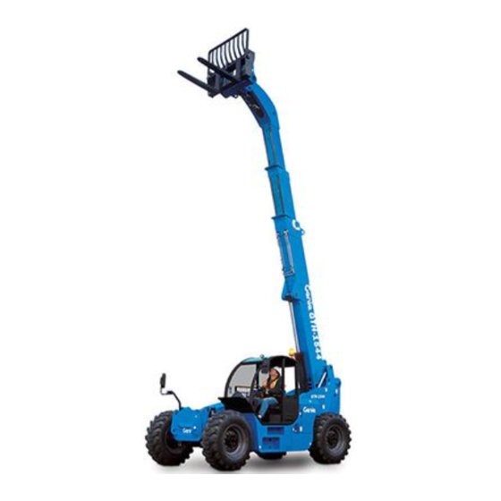
- Page 1 Operator’s Manual Serial number range GTH-1544 From GTH1513B-2 (Perkins Tier 4i) To GTH1515B-339 GTH-1544 From GTH1513B-1 (Deutz Tier 4i) plus 24273 To GTH1515B-339 Original Instructions First Edition Seventh Printing April 2017 Part No. 57.0009.0610...
-
Page 2: Table Of Contents
Copyright © 2017 by Terex Corporation First Edition: Seventh Printing, April 2017 Genie is a registered trademark of Terex South Dakota, Inc. in the U.S.A. and many other countries. “GTH” is a trademark of Terex SouthDakota, Inc. GTH-1544 Part No. -
Page 3: Introduction
First Edition - Seventh Printing April 2017 Introduction About This Manual Intended Use Genie appreciates your choice of our machine for A variable reach rough terrain forklift truck is defined your application. Our number one priority is user as a wheeled type truck with a pivoting boom, which safety, which is best achieved by our joint efforts. - Page 4 April 2017 First Edition - Seventh Printing Introduction Contacting the Manufacturer At times it may be necessary to contact Genie. When you do, be ready to supply the model number and serial number of your machine, along with your name and contact information. At minimum, Genie should be contacted for: •...
- Page 5 First Edition - Seventh Printing April 2017 Introduction Danger Failure to obey the instructions and safety rules in this manual will result in death or serious injury. Do Not Operate Unless: You learn and practice the principles of safe machine operation contained in this operator’s manual.
- Page 6 April 2017 First Edition - Seventh Printing Introduction Hazard Classification Standards Safety alert symbol - used to Many aspects of rough terrain forklift operation and alert you to potential personal testing are discussed in standards published by injury hazards. Obey all safety the American National Standards Institute and the messages that follow this Industrial Truck Standards Development Foundation.
-
Page 7: Symbol And Hazard Pictorials Definitions
First Edition - Seventh Printing April 2017 Symbol and Hazard Pictorials Definitions Maintain required Electrocution Crush hazard. No people under Injection hazard Read the operator's clearance. manual. hazard load Use a piece of Maintain required cardboard or paper Always wear seat Tip-over hazard Tip-over hazard Crush hazard. -
Page 8: General Safety
April 2017 First Edition - Seventh Printing General Safety GTH-1544 Part No. 57.0009.0610... - Page 9 First Edition - Seventh Printing April 2017 General Safety Part No. 57.0009.0610 GTH-1544...
-
Page 10: Work Area Safety
April 2017 First Edition - Seventh Printing Work Area Safety Overturning Hazards Using the load chart, confirm that Do not raise the boom unless the the load is within the rated capacity machine is level. The machine level of the machine. Do not exceed the indicator should be at zero degrees. - Page 11 First Edition - Seventh Printing April 2017 Work Area Safety Do not operate the machine in strong or gusty winds. Limit travel path and speed according to the condition Do not increase the surface area of the carriage or of the ground surface, traction, slope, location of load.
- Page 12 April 2017 First Edition - Seventh Printing Work Area Safety Collision Hazards Fall Hazards Keep people, equipment and Always wear a seat belt when material out of the work area. operating the machine. Do not operate the machine while people are under or near an elevated boom, whether it is Always remain completely inside the cab when loaded or unloaded.
- Page 13 First Edition - Seventh Printing April 2017 Work Area Safety Bodily Injury Hazards Damaged Machine Hazards Always adjust the seat and fasten Do not use a damaged or malfunctioning machine. the seat belt before starting the engine. Conduct a thorough pre-operation inspection of the machine and test all functions before each work shift.
- Page 14 April 2017 First Edition - Seventh Printing Work Area Safety Component Damage Hazards Explosion and Fire Hazards Do not use any battery or charger greater than 12V Do not start the engine if you smell or detect liquid to jump-start the engine. petroleum gas (LPG), gasoline, diesel fuel or other explosive substances.
- Page 15 First Edition - Seventh Printing April 2017 Work Area Safety Electrocution Hazards Do not use the machine as a ground for welding. Always contact the electrical power line owner. The This machine is not electrically insulated and will electrical power shall be disconnected or the power not provide protection from contact with or lines moved or insulated before machine proximity to electrical current.
- Page 16 April 2017 First Edition - Seventh Printing Work Area Safety Battery Safety Employer's Responsibilities Burn Hazards Employers are responsible for providing a safe work environment and for complying with local and Batteries contain acid. national governmental regulations. Always wear protective clothing and eye wear when working with batteries.
-
Page 17: Legend
First Edition - Seventh Printing April 2017 Legend 1. Left/right level indicator 13. Brake pedal 2. Steering wheel 14. Accelerator pedal 3. Control handle 15. Transmission control lever 4. Rear convex mirror 16. Load charts 5. Boom angle indicator 17. Front/rear level indicator 6. - Page 18 April 2017 First Edition - Seventh Printing Controls 22 14 20 Control Panel 1. Steering wheel 14. Windshield washer switch (if equipped) 2. Horn button 15. Windshield wiper switch (if equipped) 3. Heater and Air conditioning controls (if equipped) 16. Work lights switch (if equipped) 4.
-
Page 19: Controls
First Edition - Seventh Printing April 2017 Controls Steering wheel Control handle (single) Turn the steering wheel to the right to turn the Pull the control handle back and the boom will front wheels to the right. Turn the steering wheel raise. - Page 20 April 2017 First Edition - Seventh Printing Controls 17 Hazard warning lights switch (if equipped) 23 “Shift-on-fly” button Push the switch to turn the hazard warning Push and hold the button to shift from one gear lights on. Release the switch to turn the hazard to another when the machine is travelling.
- Page 21 First Edition - Seventh Printing April 2017 Controls °c 1230 engine rpm 000000.0 Instrument Panel 13. 2nd gear engaged indicator light 1. Low engine oil pressure indicator light 14. 1st gear engaged indicator light 2. Parking brake engaged indicator light 15.
- Page 22 April 2017 First Edition - Seventh Printing Controls indicator light 1 Low engine oil pressure indicator light 11 DPF Alert When illuminated this light indicates that the engine This light flashes to warn of a problem of the engine. oil pressure is too low which can lead to machine To identify the problem, see the two sections “Engine damage.
-
Page 23: Inspections
First Edition - Seventh Printing April 2017 Inspections Pre-operation Inspection Fundamentals It is the responsibility of the operator to perform a pre-operation inspection and routine maintenance. The pre-operation inspection is a visual inspection Do Not Operate Unless: performed by the operator prior to each work shift. The inspection is designed to discover if anything is apparently wrong with a machine before the operator ... - Page 24 April 2017 First Edition - Seventh Printing Inspections Pre-operation Inspection Be sure that the operator’s, safety and Engine and related components responsibilities manuals are complete, legible Limit switches and in the storage container located in the platform. ...
- Page 25 First Edition - Seventh Printing April 2017 Inspections Function Test Fundamentals The function tests are designed to discover any malfunctions before the machine is put into service. The operator must follow the step-by-step instructions to test all machine functions. A malfunctioning machine must never be used. If Do Not Operate Unless: malfunctions are discovered, the machine must be tagged and removed from service.
- Page 26 April 2017 First Edition - Seventh Printing Inspections Function Tests Test the Control Handle Select a test area that is firm, level and free of obstruction. Be sure there is no load on the forks 17 Start the machine with the parking brake on or attachment.
- Page 27 First Edition - Seventh Printing April 2017 Inspections Test the Steering Test the Transmission and Brakes 21 Rotate the steer selector to the right side to select 29 Be sure the boom is fully lowered and retracted. four-wheel steer. 30 Step on the brake pedal. Push the top of the 22 Check the steering operation by turning the parking brake switch to turn it off.
- Page 28 April 2017 First Edition - Seventh Printing Inspections Test the “Shift-on-fly” System Test the Lights (if equipped) 36 Be sure the boom is fully lowered and retracted. 47 Verify that all lights are functional. 37 Step on the brake pedal. Push the top of the parking brake switch to turn it off.
- Page 29 First Edition - Seventh Printing April 2017 Inspections Workplace Inspection Checklist Be aware of and avoid the following hazardous situations: drop-offs or holes bumps, floor obstructions or debris Do Not Operate Unless: sloped surfaces You learn and practice the principles of safe ...
- Page 30 April 2017 First Edition - Seventh Printing Inspections Inspection for Decals with Words Determine whether the decals on your machine have words or symbols. Use the appropriate inspection to verify that all decals are legible and in place. Part No. Decal Description Part No.
- Page 31 First Edition - Seventh Printing April 2017 Inspections 09.4618.1632 97602 09.4618.1655 97667 237601 237605 82558 09.4618.1638 09.4618.1625 09.4618.1646 09.4618.1633 97667 237598 09.4618.1672 09.4618.1631 214418 237598 09.4618.1834 237970 28175 97667 28236 237606 09.4618.1622 09.4618.1418 load chart set 09.4618.1399 09.4618.1845 09.4618.1619 09.4618.1631 82366 09.4618.1618 237598...
-
Page 32: Operating Instructions
April 2017 First Edition - Seventh Printing Operating Instructions Fundamentals The Operating Instructions section provides instructions for each aspect of machine operation. It is the operator’s responsibility to follow all the safety rules and instructions in the operator’s, safety and responsibilities manuals. Do Not Operate Unless: A variable reach rough terrain forklift truck is defined as a wheeled type truck designated... - Page 33 First Edition - Seventh Printing April 2017 Operating Instructions Parking Brake Steer Select Use the parking brake switch to apply the parking Always position all wheels in line with the machine brake before raising the boom or leaving the before switching the steering mode. machine.
- Page 34 April 2017 First Edition - Seventh Printing Operating Instructions Transmission Control When the indicator light is OFF, the travelling Use the transmission control lever to control the speed is beyond the admissible speed range and, direction of machine travel. by pressing the switch, gear won’t be shifted. Step on the service brake pedal before putting the If the indicator light flashes, there are errors or transmission into gear.
- Page 35 First Edition - Seventh Printing April 2017 Operating Instructions Frame Sway Control Before raising the boom, the machine must be level. Move the transmission control lever to Check the left to right level indicator. The left neutral. to right level indicator should be 0 degrees Warm up the engine;...
- Page 36 April 2017 First Edition - Seventh Printing Operating Instructions DPF Ash Load Monitoring (Deutz configuration) (Perkins configuration) During the whole engine lifetime, the DPF collects In this configuration regeneration always starts ash which cannot be removed by regeneration automatically. process. Only when temperature is below -18°C, the The ash load leads to shortened regeneration system is not able to activate the regeneration by...
- Page 37 First Edition - Seventh Printing April 2017 Operating Instructions Transporting a Load Raising and Placing a Load Center the load on the forks. Position the load so The load chart in the cab shows the operating that it is completely against the back of the fork limits of a properly maintained and operated frame.
- Page 38 April 2017 First Edition - Seventh Printing Operating Instructions Gradually move the controller to raise and Gradually move the controller to raise and extend the boom to the required height. retract the boom. This will bring the forks out of the load. When the forks are clear of the load and the structure, the boom can be lowered and retracted.
- Page 39 First Edition - Seventh Printing April 2017 Operating Instructions Controller movements Control handle only Control handle only Control handle only with grey thumb switch with grey finger switch Part No. 57.0009.0610 GTH-1544...
- Page 40 April 2017 First Edition - Seventh Printing Operating Instructions Rear Axle Lock Version with hydraulic locking (optional) 1. Drive to the place where you will release the If the boom is raised above 50°, the transmission mounted attachment (when possible, a solid will shift to neutral and the frame sway function will and sheltered site).
- Page 41 First Edition - Seventh Printing April 2017 Operating Instructions Engine Condition Indicator Jump Starting the Machine If the DPF Alert indicator light and/or the Engine Jump starting at the battery or battery replacement Critical Fault indicator light switch on, contact is required when the battery is discharged to the service personnel.
- Page 42 April 2017 First Edition - Seventh Printing Operating Instructions Driving on a slope When the machine is loaded, always travel with the load uphill. When the machine is unloaded, travel with the forks or attachment downhill. On steep terrain, drive only up and down hill, and always keep the machine in gear.
-
Page 43: Transport And Lifting Instructions
First Edition - Seventh Printing April 2017 Transport and Lifting Instructions Before loading for transport, make sure the deck, ramps and machine tires are free of mud, snow and ice. Failure to do so could cause the machine to slide. ... - Page 44 April 2017 First Edition - Seventh Printing Transport and Lifting Instructions Securing to Truck or Trailer for Transit Securing the Chassis Turn the key switch to the off position and remove Use chains of ample load capacity. the key before transporting. Use a minimum of 6 chains.
- Page 45 First Edition - Seventh Printing April 2017 Transport and Lifting Instructions Lifting Instructions Fully lower and retract the boom. Determine the center of gravity of your machine using the picture on this page. Remove all loose items on the machine. Observe and Obey: Attach the rigging only to the designated lifting points on the machine.
-
Page 46: Maintenance
April 2017 First Edition - Seventh Printing Maintenance Diesel Fuel Requirements Satisfactory engine performance is dependent on the use of a good quality fuel. The use of a good quality fuel will give the following result: long engine life and acceptable exhaust emissions Observe and Obey: levels. - Page 47 First Edition - Seventh Printing April 2017 Maintenance Check the Engine Oil Level Check the Hydraulic Oil Level Maintaining the proper engine oil level is essential Maintaining the hydraulic oil at the proper level is to good engine performance and service life. essential to machine operation.
- Page 48 April 2017 First Edition - Seventh Printing Maintenance Check the Engine Coolant Level - Check the Tire Pressure Liquid Cooled Models Tip-over hazard. An over-inflated tire can explode which may compromise machine Maintaining the engine coolant at the proper level stability and cause the machine to tip over.
- Page 49 First Edition - Seventh Printing April 2017 Maintenance Check the Battery Scheduled Maintenance Maintenance performed quarterly, annually and every two years must be completed by a person trained and qualified to perform maintenance on Proper battery condition is essential to good this machine according to the procedures found in machine performance and operational safety.
-
Page 50: Attachments
April 2017 First Edition - Seventh Printing Attachments Work Platform Hazards Always perform a pre-operation inspection of the platform, per the manufacturer’s instructions, prior Work Area Safety to use. If damage or any unauthorized variation from The telehandler shall not be used to lift people factory delivered condition is discovered, the unless there is no other practical option. - Page 51 First Edition - Seventh Printing April 2017 Attachments Occupying the Platform Do not place or attach overhanging loads to any part of this machine or platform. Do not carry materials directly on platform railing unless approved by Genie. Do not place ladders or Be certain that materials and tools are protected scaffolds in the platform or from falling out of the platform.
- Page 52 April 2017 First Edition - Seventh Printing Attachments Telehandler Operation Lifting Personnel Be certain that the platform is securely attached to Occupants, equipment and GTH-1544 the telehandler, lifting carriage and forks. 30 ft 25 ft 20 ft 15 ft 10 ft 5 ft...
- Page 53 First Edition - Seventh Printing April 2017 Attachments Operating Instructions Keep bystanders away while operating. Do not place boom or platform against any Preparation and Setup structure to steady the platform or to support the structure. Read, understand and obey all jobsite, local, Do not use the controls to free a platform that is state, federal and provincial rules, standards caught, snagged or otherwise prevented from...
- Page 54 April 2017 First Edition - Seventh Printing Attachments Installing and securing the platform Lifting and lowering the platform Center the platform on the telehandler. Set the parking brake and place the transmission into neutral. Properly secure the platform to the telehandler according to the manufacturer’s instructions.
- Page 55 First Edition - Seventh Printing April 2017 Attachments Overturning Hazards Suspended Load Hazards Work Area Safety Do not lift a suspended load without the proper and legible load capacity chart for the attachment/ General Safety telehandler combination you are using. Do not permit Do not lift a suspended load without first the load to swing...
- Page 56 April 2017 First Edition - Seventh Printing Attachments Collision Hazards Identify the proper lifting points of the load, taking into consideration the center of gravity and load Be sure that the load is clear of any adjacent stability. obstacles before lifting. Do not attempt to use the telehandler frame- When visibility is or could be obstructed, near leveling to compensate for a swinging load or to...
- Page 57 First Edition - Seventh Printing April 2017 Attachments Lifting a Suspended Load Travelling Verify that landing point is level and can safely Be sure that the path of travel is level and capable support the load. of supporting the telehandler with its load. Properly secure the attachment to the telehandler Keep the boom, and load, as low as practical while maintaining visibility in the direction of travel.
- Page 58 April 2017 First Edition - Seventh Printing Attachments Placing the Load Signal Person (from 1926.1419) Ask a signal person to assist with placing the Per OSHA CFR 1926.1419, a signal person is load if visibility will be obstructed at the point of required when: operation.
- Page 59 First Edition - Seventh Printing April 2017 Attachments STOP. With arm EMERGENCY STOP. With both arms extended HOIST. With upper RAISE BOOM. With extended horizontally to horizontally to the side, palms down, arms are arm extended to the arm extended the side, palm down, swung back and forth.
- Page 60 April 2017 First Edition - Seventh Printing Attachments Suspended Load Hazards Rigger Requirements (from OSHA CFR 1926.404) When employees are engaged in hooking, unhooking, or guiding the load, or in the initial connection of a load to a component or structure and are within the fall zone, all of the following criteria must be met: The materials being hoisted must be rigged to...
-
Page 61: Specifications
First Edition - Seventh Printing April 2017 Specifications GTH-1544 Height, stowed 8 ft 7 in 2.61 m Length, stowed, without 20 ft 4 in 6.20 m forks Width, standard tires 7 ft 11 in 2.42 m Wheelbase 11 ft 6 in 3.50 m Ground clearance, center 1 ft 3 in... -
Page 62: Load Charts
April 2017 First Edition - Seventh Printing Load Charts GTH-1544, Standard Carriage 30 ft 25 ft 20 ft 15 ft 10 ft 5 ft 0 ft 9.14 m 7.62 m 6.10 m 4.57 m 3.05 m 1.52 m 75° 45 ft 70°... - Page 63 First Edition - Seventh Printing April 2017 Load Charts GTH-1544, 7 ft Truss Boom 35 ft 30 ft 25 ft 20 ft 15 ft 10 ft 5 ft 0 ft 10.67 m 9.14 m 7.62 m 6.10 m 4.57 m 3.05 m 1.52 m 45 ft...
- Page 64 April 2017 First Edition - Seventh Printing Load Charts GTH-1544, Shackle GTH-1544 09.4618.1868 GTH-1544 Part No. 57.0009.0610...
- Page 65 California Proposition 65 Warning The exhaust from this product contains chemicals known to the State of California to cause cancer, birth defects or other reproductive harm. www.genielift.com...
Need help?
Do you have a question about the Genie GTH1513B-2 and is the answer not in the manual?
Questions and answers