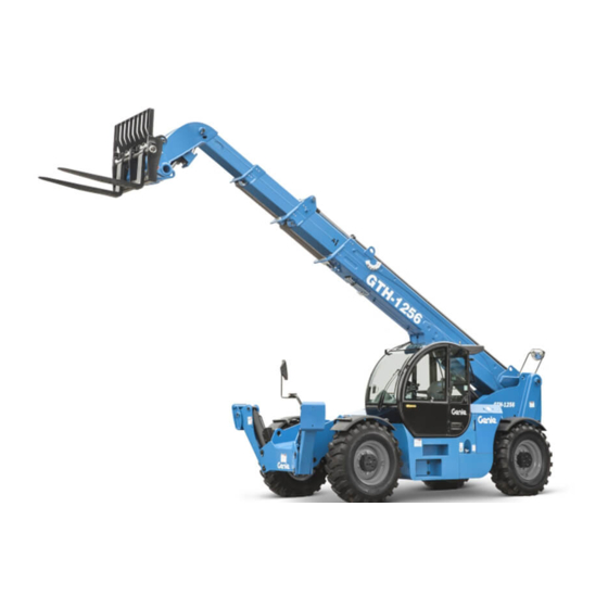
Terex Genie GTH-1256 Operator's Manual
Hide thumbs
Also See for Genie GTH-1256:
- Operator's manual (82 pages) ,
- Service and repair manual (136 pages) ,
- Maintenance manual (54 pages)

Related Manuals for Terex Genie GTH-1256


Summary of Contents for Terex Genie GTH-1256
- Page 1 Operator’s Manual Serial number range GTH-1256 (Deutz Tier 4 Final) From GTH12M-401 Original Instructions First Edition Second Printing April 2019 Part No. 57.0009.0737...
-
Page 2: Table Of Contents
Copyright © 2017 by Terex Corporation First Edition: Second Printing, April 2019 Genie is a registered trademark of Terex South Dakota, Inc. in the U.S.A. and many other countries. “GTH” is a trademark of Terex SouthDakota, Inc. Complies with ANSI/ITSDF B56.6, CSA B335 GTH-1256... -
Page 3: Introduction
First Edition - Second Printing April 2019 Introduction About This Manual Intended Use Genie appreciates your choice of our machine for A variable reach rough terrain forklift truck is defined your application. Our number one priority is user as a wheeled type truck with a pivoting boom, which safety, which is best achieved by our joint efforts. - Page 4 April 2019 First Edition - Second Printing Introduction Contacting the Manufacturer At times it may be necessary to contact Genie. When you do, be ready to supply the model number and serial number of your machine, along with your name and contact information. At minimum, Genie should be contacted for: •...
- Page 5 First Edition - Second Printing April 2019 Introduction Danger Failure to obey the instructions and safety rules in this manual will result in death or serious injury. Do Not Operate Unless: You learn and practice the principles of safe machine operation contained in this operator’s manual.
- Page 6 April 2019 First Edition - Second Printing Introduction Hazard Classification Standards Safety alert symbol - used to Many aspects of rough terrain forklift operation and alert you to potential personal testing are discussed in standards published by injury hazards. Obey all safety the American National Standards Institute and the messages that follow this Industrial Truck Standards Development Foundation.
-
Page 7: Symbol And Hazard Pictorials Definitions
First Edition - Second Printing April 2019 Symbol and Hazard Pictorials Definitions Electrocution Maintain required Crush hazard No people under Read the operator's Injection hazard hazard clearance load manual Use a piece of cardboard or paper to search Maintain required Crush hazard Always wear seat Tip-over hazard... -
Page 8: General Safety
April 2019 First Edition - Second Printing General Safety GTH-1256 Part No. 57.0009.0737... - Page 9 First Edition - Second Printing April 2019 General Safety Part No. 57.0009.0737 GTH-1256...
-
Page 10: Work Area Safety
April 2019 First Edition - Second Printing Work Area Safety Do not attemp to jump free of the machine during a Tip-over Hazards tip-over. The ROPS (Roll Over Protective Structure) is designed to protect you. Using the appropriate load chart for the machine configuration, confirm If the telehandler starts to that the load is within the rated... - Page 11 First Edition - Second Printing April 2019 Work Area Safety Lateral inclination allowed during working Do not raise a load unless the load phase ± 0,5° is properly positioned or secured on the forks or approved attachment. Only use the machine on firm ground capable of supporting the maximum combined load of the machine and payload.
- Page 12 April 2019 First Edition - Second Printing Work Area Safety Make sure the machine (wheels and stabilizers) Traveling on Slopes Hazards rests on a firm ground to prevent hazardous unstable conditions. If the ground is not firm enough, position some support planks, capable of withstanding the When driving, keep the boom at expected loads, under the stabilizers or the wheels.
- Page 13 First Edition - Second Printing April 2019 Work Area Safety Do not raise the boom unless the brake is applied. Fall Hazards Do not operate, without fenders, in conditions where Always wear a seat belt when loose debris could hit the operator or accumulate on operating the machine.
- Page 14 April 2019 First Edition - Second Printing Work Area Safety Falling Object Hazards Bodily Injury Hazards Operate the machine at speeds that will keep the Always adjust the seat and fasten load under control. Start and stop movements the seat belt before starting the smoothly.
- Page 15 First Edition - Second Printing April 2019 Work Area Safety Damaged Machine Hazards Component Damage Hazards Do not use any battery or charger greater than 12V Do not use a damaged or malfunctioning machine. to jump-start the engine. Conduct a thorough pre-operation inspection of the Do not use the machine as a ground for welding.
- Page 16 April 2019 First Edition - Second Printing Work Area Safety Crush Hazards Explosion and Fire Hazards Do not start the engine if you smell or detect liquid Keep clear of moving stabilizers petroleum gas (LPG), gasoline, diesel fuel or other explosive substances.
- Page 17 First Edition - Second Printing April 2019 Work Area Safety Do not use the machine as a ground for welding. Electrocution Hazards Always contact the electrical power line owner. The This machine is not electrically insulated and will electrical power shall be disconnected or the power not provide protection from contact with or lines moved or insulated before machine proximity to electrical current.
- Page 18 April 2019 First Edition - Second Printing Work Area Safety Electrocution Hazard Battery Safety Burn Hazards Avoid contact with electrical terminal. Batteries contain acid. During maintenance or repair works, and while Always wear protective welding, disconnect the battery turning the cut-out clothing and eye wear when switch (see Inspection for Decals section).
-
Page 19: Legend
First Edition - Second Printing April 2019 Legend ¢ £ ¤ ¡ © ¡ © ¨ ¥ ¡ § £ £ ¡ ¦ ¥ 1. Left/right level indicator 15. Transmission control lever 2. Steering wheel 16. Load charts 3. Control handle 17. -
Page 20: Controls
April 2019 First Edition - Second Printing Controls " " " & & Control Panel 1. Steering wheel 14. Windshield wiper switch (if equipped) 2. Horn button 15. Windshield washer switch (if equipped) 3. Heater and Air conditioning controls (if equipped) 16. - Page 21 First Edition - Second Printing April 2019 Controls Steering wheel handle back and the forks will tilt up. Hold down the grey thumb switch and push the Control Turn the steering wheel to the right to turn the handle forward and the forks will tilt down. Hold front wheels to the right.
- Page 22 April 2019 First Edition - Second Printing Controls 18 Transmission control lever/Transmission mode Move the transmission control lever forward for forward gear. Move the lever toward you for reverse gear. Move the lever to the center position for neutral. Rotate the end of the lever to pos 1 to turn the transmission on first gear fixed;...
- Page 23 First Edition - Second Printing April 2019 Controls 1230 engine rpm 000000.0 Instrument Panel 15. High engine coolant temperature gauge 16. Position light indicator light 1. Low engine oil pressure indicator light 17. Hour meter 2. Parking brake engaged indicator light 18.
- Page 24 April 2019 First Edition - Second Printing Controls 1 Low engine oil pressure indicator light 17 Hour meter When illuminated this light indicates that the engine The hour meter displays the engine operating hours. oil pressure is too low which can lead to machine When the machine speed exceeds 2 mph the hour damage.
-
Page 25: Inspections
First Edition - Second Printing April 2019 Inspections Pre-operation Inspection Fundamentals It is the responsibility of the operator to perform a pre-operation inspection and routine maintenance. The pre-operation inspection is a visual inspection Do Not Operate Unless: performed by the operator prior to each work shift. The inspection is designed to discover if anything is apparently wrong with a machine before the operator You learn and practice the principles of safe... - Page 26 April 2019 First Edition - Second Printing Inspections Pre-operation Inspection Be sure that the operator’s and safety manuals Boom wear pads are complete, legible and in the storage container Tires and wheels located in the cab. Mirrors and rear object detection system (if Be sure that all load charts are in place and legible.
- Page 27 First Edition - Second Printing April 2019 Inspections Function Test Fundamentals The function tests are designed to discover any malfunctions before the machine is put into service. The operator must follow the step-by-step instructions to test all machine functions. A malfunctioning machine must never be used. If Do Not Operate Unless: malfunctions are discovered, the machine must be tagged and removed from service.
- Page 28 April 2019 First Edition - Second Printing Inspections Function Tests Test the Control handle 17 Start the machine with the parking brake on Select a test area that is firm, level and free of and the transmission control lever set to neutral obstruction.
- Page 29 First Edition - Second Printing April 2019 Inspections Test the Steering Test the Transmission and Brakes 21 Rotate the steering mode selector to the right 29 Be sure the boom is fully lowered and retracted. side to select four-wheel steer. 30 Step on the brake pedal.
- Page 30 April 2019 First Edition - Second Printing Inspections Test the Transmission mode 48 Set parking brake. Slowly sway the machine to the left and to the right. 36 Be sure the boom is retracted and in the transport position. Result: The sway function should not operate. 37 Be sure that the parking brake is on and the transmission control lever is in neutral position .
- Page 31 First Edition - Second Printing April 2019 Inspections Test the Rear Proximity Alarm System As the machine moves away from the object, (if equipped) the display should show the green light on,and no alarm should be sounding. The system provides a visible and audible indication 57 Stop the machine, place the transmission in of objects behind the machine, when they are within neutral and turn off the engine.
- Page 32 April 2019 First Edition - Second Printing Inspections Workplace Inspection Checklist Be aware of and avoid the following hazardous situations: drop-offs or holes bumps, floor obstructions or debris Do Not Operate Unless: sloped surfaces You learn and practice the principles of safe unstable or slippery surfaces machine operation contained in this operator’s manual.
- Page 33 First Edition - Second Printing April 2019 Inspections Inspection for Decals with Words Use the pictures on the next page to verify that all decals are legible and in place. Below is a numerical list with quantities and descriptions. Part No. Decal Description Part No.
- Page 34 April 2019 First Edition - Second Printing Inspections 09.4618.1765 09.4618.2050 09.4618.1919 09.4618.1655 237601 237605 09.4618.1638 09.4618.1834 82558 09.4618.1625 09.4618.1646 09.4618.1768 97667 237598 214418 09.4618.1767 1263543 237598 237970 97667 28236 09.4618.1622 1280819 1280820 load chart set 09.4618.1418 09.4618.1399 237606 09.4618.1767 09.4618.2035 82366 09.4618.2039 237598...
-
Page 35: Operating Instructions
First Edition - Second Printing April 2019 Operating Instructions Fundamentals The Operating Instructions section provides instructions for each aspect of machine operation. It is the operator’s responsibility to follow all the safety rules and instructions in the operator’s, safety and responsibilities manuals. Do Not Operate Unless: A variable reach rough terrain forklift truck is defined as a wheeled type truck designated... - Page 36 April 2019 First Edition - Second Printing Operating Instructions Parking Brake Starting in Cold Condition Always use the parking brake switch to apply the In cold conditions, 20°F / -6°C and below, warm parking brake before raising the boom. the engine for 5 minutes before operating to prevent hydraulic system damage.
- Page 37 First Edition - Second Printing April 2019 Operating Instructions Rear Object Detection System (if Transmission Control equipped) Use the transmission control lever to control the direction of machine travel. The RODS system is intended to only augment, not replace, the operator’s direct vision or Step on the service brake pedal before putting the indirect vision using the mirrors and to provide an transmission into gear.
- Page 38 April 2019 First Edition - Second Printing Operating Instructions When the instrument panel shows the reset code RST 1: 1 turn the ignition switch off 2 turn the ignition swich on When the instrument panel shows the reset code RST 2: 1 bring the machine to a stop on a firm level surface and set the brake 2 set the transmission control lever to the...
- Page 39 First Edition - Second Printing April 2019 Operating Instructions SCR Regeneration Don’t leave the machine unattended. Signpost the area. Based on the blinking combination of the "Regen. Required." label, proceed as below: xii The regeneration lasts 35 or 40 minutes on average.
- Page 40 April 2019 First Edition - Second Printing Operating Instructions Transporting a Load Raising and Placing a Load Always center the load on the forks. Position the Always center the load on the forks. Position the load so that it is completely against the back of the load so that it is completely against the back of the fork frame.
- Page 41 First Edition - Second Printing April 2019 Operating Instructions Placing the load Gradually move the controller to lower and extend the boom into final position. Lower the Travel to the desired work site and carefully load until the weight is completely off the forks. stop the machine.
- Page 42 April 2019 First Edition - Second Printing Operating Instructions Control handle Control handle only Control handle only Control handle only with grey thumb switch with grey finger switch GTH-1256 Part No. 57.0009.0737...
- Page 43 First Edition - Second Printing April 2019 Operating Instructions Rear Axle Lock Version with hydraulic locking (optional) If the boom is raised above 50°, the transmission will shift to neutral and the frame sway function will 1. Drive to the place where you will release the not operate.
- Page 44 April 2019 First Edition - Second Printing Operating Instructions Engine Condition Indicator Jump Starting the Machine If the SCR warning light and/or the Engine Critical Jump starting at the battery or battery replacement Fault indicator light switch on, contact service is required when the battery is discharged to the personnel.
- Page 45 First Edition - Second Printing April 2019 Operating Instructions Driving on a slope Rear Proximity Alarm When the machine is loaded, always travel with The system is designed to supplement other safety the load uphill. When the machine is unloaded, practices and systems such as signal person and travel with the forks or attachment downhill.
- Page 46 April 2019 First Edition - Second Printing Operating Instructions Inactivity at Low Temperature In case of inactivity of the machine at low temperature, make sure to store it with the boom fully retracted in order to avoid any ice accretion on its upper surface.
-
Page 47: Transport And Lifting Instructions
First Edition - Second Printing April 2019 Transport and Lifting Instructions Before loading for transport, make sure the deck, ramps and machine tires are free of mud, snow and ice. Failure to do so could cause the machine to slide. Be sure the vehicle capacity, loading surfaces and chains or straps are sufficient to withstand Observe and Obey:... - Page 48 April 2019 First Edition - Second Printing Transport and Lifting Instructions Securing to Truck or Trailer for Transit Securing the Chassis Turn the key switch to the off position and remove Use chains of ample load capacity. the key before transporting. Use a minimum of 6 chains.
- Page 49 First Edition - Second Printing April 2019 Transport and Lifting Instructions Lifting Instructions Fully lower and retract the boom. Retract the stabilizers. Determine the center of gravity of your machine using the picture on this page. Observe and Obey: Remove all loose items on the machine. Only qualified riggers should rig the machine.
-
Page 50: Maintenance
April 2019 First Edition - Second Printing Maintenance Diesel Fuel Requirements Satisfactory engine performance is dependent on the use of a good quality fuel. The use of a good quality fuel will give the following result: long engine life and acceptable exhaust emissions Observe and Obey: levels. - Page 51 First Edition - Second Printing April 2019 Maintenance Check the Engine Oil Level Maintaining the proper engine oil level is essential Visually inspect the DEF indicator light on the to good engine performance and service life. dashboard. Operating the machine with an improper oil level Result: Light flashing indicates DEF level is low.
- Page 52 April 2019 First Edition - Second Printing Maintenance Check the Engine Coolant Level - Check the Tire Pressure Liquid Cooled Models Tip-over hazard. An over-inflated tire can explode which may compromise machine Maintaining the engine coolant at the proper level stability and cause the machine to tip over.
- Page 53 First Edition - Second Printing April 2019 Maintenance Check the Battery Drain the Fuel/Water Separator Proper battery condition is essential to good Proper maintenance of the fuel filter/water machine performance and operational safety. separator is essential for good engine Improper fluid levels or damaged cables and performance.
-
Page 54: Attachments
April 2019 First Edition - Second Printing Attachments Always perform a pre-operation inspection of the Work Platform Hazards platform, per the manufacturer’s instructions, prior to use. Work Area Safety If damage or any unauthorized variation from The telehandler shall not be used to lift people factory delivered condition is discovered, the unless there is no other practical option. - Page 55 First Edition - Second Printing April 2019 Attachments Do not place or attach overhanging loads to any Occupying the Platform part of this machine or platform. Do not carry materials directly on platform railing unless approved by Genie. Do not place ladders or Be certain that materials and tools are protected scaffolds in the platform or from falling out of the platform.
- Page 56 April 2019 First Edition - Second Printing Attachments Telehandler Operation Lifting Personnel Be certain that the platform is securely attached to Occupants, equipment and GTH-1544 the telehandler, lifting carriage and forks. materials shall not exceed the maximum platform capacity. Be certain that the lifting carriage and forks are Distribute loads evenly on the secured to prevent them from pivoting freely.
- Page 57 First Edition - Second Printing April 2019 Attachments Keep bystanders away while operating. Operating Instructions Do not place boom or platform against any Preparation and Setup structure to steady the platform or to support the structure. Read, understand and obey all jobsite, local, Do not use the controls to free a platform that is state, federal and provincial rules, standards caught, snagged or otherwise prevented from...
- Page 58 April 2019 First Edition - Second Printing Attachments Installing and securing the platform Lifting and lowering the platform Center the platform on the telehandler. Set the parking brake and place the transmission into neutral. Properly secure the platform to the telehandler according to the manufacturer’s instructions.
- Page 59 First Edition - Second Printing April 2019 Attachments Overturning Hazards Suspended Load Hazards Work Area Safety Do not lift a suspended load without the proper and legible load capacity chart for the attachment/ General Safety telehandler combination you are using. Do not permit Do not lift a suspended load without first the load to swing...
- Page 60 April 2019 First Edition - Second Printing Attachments All movements of the load must be accomplished Fall Hazards gradually and at the slowest practical speed to Do not lift or suspend personnel. prevent the load from swinging. Keep the heavy part of the load closest to the Collision Hazards attachment.
- Page 61 First Edition - Second Printing April 2019 Attachments Lifting a Suspended Load Travelling Verify that landing point is level and can safely Be sure that the path of travel is level and capable support the load. of supporting the telehandler with its load. Properly secure the attachment to the telehandler.
- Page 62 April 2019 First Edition - Second Printing Attachments Placing the Load Signal Person (from 1926.1419) Ask a signal person to assist with placing the Per OSHA CFR 1926.1419, a signal person is load if visibility will be obstructed at the point of required when: operation.
- Page 63 First Edition - Second Printing April 2019 Attachments STOP. With arm EMERGENCY STOP. With both arms extended HOIST. With upper RAISE BOOM. With extended horizontally to horizontally to the side, palms down, arms are arm extended to the arm extended the side, palm down, swung back and forth.
- Page 64 April 2019 First Edition - Second Printing Attachments Suspended Load Hazards Rigger Requirements (from OSHA CFR 1926.404) When employees are engaged in hooking, unhooking, or guiding the load, or in the initial connection of a load to a component or structure and are within the fall zone, all of the following criteria must be met: The materials being hoisted must be rigged to...
-
Page 65: Specifications
First Edition - Second Printing April 2019 Specifications Rear Object Detection System Refer to supplemental GTH-1256 manuals Height, stowed 8 ft 9 in 2.67 m Floor loading information Length, stowed, without 21 ft 6.40 m Tire load, maximum 19,841 lbs 9,000 kg forks Occupied floor pressure... - Page 66 April 2019 First Edition - Second Printing Specifications Rear proximity Sensor Range Approximate detection range. Minimum rear proximity sensor detection height is 2 ft / 0.6 m. GTH-1256 Part No. 57.0009.0737...
-
Page 67: Load Charts
First Edition - Second Printing April 2019 Load Charts Load Capacity Field Calculations a specific load zone. Note that this does not account for a load center that is not Always center the load on the forks. centered between the forks or a vertical Position the load so that it is completely load center exceeding 24 in / 61 cm from the top face of the fork tine. - Page 68 April 2019 First Edition - Second Printing Load Charts GTH-1256, Standard Carriage GTH-1256, Rotating Carriage stabilizers up stabilizers up GTH-1256, Rotating Carriage GTH-1256, Standard Carriage stabilizers down stabilizers down GTH-1256 Part No. 57.0009.0737...
- Page 69 First Edition - Second Printing April 2019 Load Charts G T H - 1 2 5 6 , R u b b i s h B u c k e t GTH-1256, 7 ft Truss Boom stabilizers up stabilizers up GTH-1256 GTH-1256, 7 ft Truss Boom G T H - 1 2 5 6 , R u b b i s h B u c k e t...
- Page 70 April 2019 First Edition - Second Printing Load Charts GTH-1256, Shackle stabilizers up GTH-1256, Shackle stabilizers down GTH-1256 Part No. 57.0009.0737...
- Page 71 California Proposition 65 WARNING Operating, servicing and maintaining this equipment, passenger vehicle or off-highway motor vehicle can expose you to chemicals including engine exhaust, carbon monoxide, phthalates, and lead, which are known to the State of California to cause cancer and birth defects or other reproductive harm.
Need help?
Do you have a question about the Genie GTH-1256 and is the answer not in the manual?
Questions and answers