
Related Manuals for Proceq ZAA2600


Summary of Contents for Proceq ZAA2600
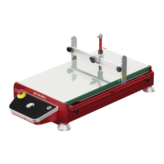
- Page 1 ZAA2600 Versions ZAA2600.A, ZAA2600.HA ZAA2600.C ZAA2600.SW Automatic Film Applicator and Testing System Instruction Manual...
- Page 2 Proceq SA Ringstrasse 2 CH-8603 Schwerzenbach Switzerland Classification: Manual Revision History Date Author, Comments Sep 3, 2021 PEGG Initial document copied from ZAA 2600.A_v1.4_en and ZAA 2600.HA_v1.4_en_heatable version.docx, ZAA 2600.SW_v1.2_en and … 23. September 2021 © Copyright 2021, PROCEQ SA...
-
Page 3: Table Of Contents
3.2.2 Accessories to ZAA2600.C Crockmeter ................. 16 3.2.3 Options for ZAA 2600.SW as well as ZAA 2600 equipped with ACC1286 ....... 17 3.2.4 Accessories for ZAA2600.C for scratch and mar resistance tests ........18 Modification sets ......................18 ZAA2600.HA ........................18 Device Overview ...................... - Page 4 10.5.3 Cycle speed and stroke length cannot be set.............. 69 10.5.4 The motor is overheated .................... 69 10.5.5 Lubrication the guide rods ..................69 10.6 Emergency Stop function ....................70 Turning the glass plate of a ZAA2600.A ..............71 23. September 2021 © Copyright 2021, PROCEQ SA...
- Page 5 ZAA2600 - Manual Removing the heating plate of a ZAA2600.HA ............72 Converting from applicator into basic unit .............. 73 Converting from basic unit into applicator .............. 74 Maintenance and Cleaning ..................75 15.1 Maintenance and cleaning work that can be carried out by the user ....... 75 15.2...
- Page 6 Illustrations, descriptions as well as the technical specifications conform to the instruction manual at hand at the time of publishing or printing. However, Proceq SA policy is one of continuous product development. All changes resulting from technical progress, modified construction or similar are reserved without obligation for Proceq to update.
-
Page 7: Safety Notes
Tilting the device can lead to falling out of the glass plate. All maintenance and repair not explicitly allowed and described in this manual, shall only be carried out by Proceq SA or an authorized Proceq partner, failure to comply voids warranty. - Page 8 ZAA2600 - Manual Proceq SA refuses all warranty and liability claims for damages caused by usage of the product in combination with non-original accessories, or accessories from 3 party suppliers. All local safety regulations apply for the operation of the product.
-
Page 9: Introduction
The ZAA 2600 is an automatic laboratory equipment, with a high degree of flexibility. Due to it’s modular setup, the ZAA2600 can be used as an automatic film applicator or an automated test system for linear abrasion tests (Crockmeter, Scrub Tester) and scratch resistance tests. -
Page 10: Film Testing
23. September 2021 © Copyright 2021, PROCEQ SA... -
Page 11: Versions And Features
ZHT2093 (Adapter required) ZAA2600.SW Automatic Scrub Tester 2.4 Modification sets As the ZAA2600 is a modular film application and testing system. Any ZAA2600 can be modified and expanded. The following modification sets are available ACC1284 modification set „Heatable Application“... -
Page 12: Key Features
ZAA2600 - Manual 2.5 Key Features The ZAA2600 film application and testing system has the following features: Thanks to its modular construction, the automatic universal unit can be equipped with different kits for carrying out also scrub resistance, washability, crocking and scratch resistance tests as well as recording of the drying time. -
Page 13: Scope Of This Document
ZAA2600 - Manual 2.6 Scope of this document This document is an instruction manual for the ZAA2600 automatic film application and testing system, which describes the correct use of the equipment. This manual covers the film applicator models of the ZAA2600 series (ZAA2600 and ZAA2600.H) and the automatic film testers ZAA2600.C and ZAA2600.SW. -
Page 14: Scope Of Delivery
ZAA2600 - Manual 3 Scope of Delivery 3.1 Standard delivery The following parts are included in the delivery of all versions: ZAA2600 Basic unit with touchscreen Reversible, double sided glass plate: printing blanket and glass surface 4 rubber feet ... -
Page 15: Accessories
ZAA2600 - Manual 3.2 Accessories 3.2.1 Accessories to ZAA2600.A film applicators Description ACC121 Precision-vacuumplates with a series of holes of 1 mm (0.04”) ACC211 Precision-vacuumplates with a series of holes of 0.5 mm (0.02”) ACC039 Vacuum pumps with hose – 230 V ACC122 Vacuum pumps with hose –... -
Page 16: Accessories To Zaa2600.C Crockmeter
ZAA2600 - Manual 3.2.2 Accessories to ZAA2600.C Crockmeter ACC1315 Friction finger set A acc. to EN ISO 21546 1 friction finger holder 1 friction finger A (22 mm x 22 mm / 0.87” x 0.87”) 1 set rubbing cloth clamp (ACC1350) -
Page 17: Options For Zaa 2600.Sw As Well As Zaa 2600 Equipped With Acc1286
5 abrasive pads (3M Scotch Brite®) – ACC1483) 1 holder ACC1482 Weight 50 g ACC1484 Weight 100 g ACC1486 Weight 500 g ACC1469 Universal holder 1 holder 1 foam cushion – ACC1512 1 hard rubber cushion– ACC1577 23. September 2021 © Copyright 2021, PROCEQ SA... -
Page 18: Accessories For Zaa2600.C For Scratch And Mar Resistance Tests
Adapter for scratch and mar resistance tests (Holder for ZHT 2093 and ZST 2095) 3.3 Modification sets As the ZAA2600 is a modular film application and testing system. The ZAA2600 can be modified and expanded. The following modification sets are available ACC1284 modification set „Heatable Application“... - Page 19 ACC1477.230V Version for 230 V mains supply ACC1477.115V Version for115 V mains supply Proceq SA refuses all warranty and liability claims for damages caused by usage of the ZAA2600 in combination with non-original accessories, or accessories from 3 party suppliers 23.
-
Page 20: Device Overview
ZAA2600 - Manual 4 Device Overview 4.1 ZAA2600.A (16) (11) (17) (12) (10) (19) (18) 4.2 ZAA2600.HA (22) (21) (11) (17) (12) (20) (10) (19) (18) 23. September 2021 © Copyright 2021, PROCEQ SA... -
Page 21: Zaa2600.C
ZAA2600 - Manual 4.3 ZAA2600.C (27) (31) (29) (30) (11) (28) (17) (12) (26) (10) (19) (18) 4.4 ZAA2600.SW (38) (36) (33) (35) (39) (37) (11) (12) (34) (17) (19) (32) (10) (18) 23. September 2021 © Copyright 2021, PROCEQ SA... - Page 22 Glass plate (ZAA2600.C only) (27) Tool holder bridge (ZAA2600.C only) (28) Tool holder side part (ZAA2600.C only) (29) Height adjustment for tool holder (ZAA2600.C only) (30) Friction finger set (ZAA2600.C only) (31) Crock Tool holder (ZAA2600.C only) (32) Sample Tray (ZAA2600.SW only) (33) Scrub Tool holder (ZAA2600.SW only)
-
Page 23: Assembly And Starting Up
5.1 Initial Assembly Before the first use the apparatus has to be assembled or converted for use with the desired options. 5.1.1 Assembly of ZAA2600.A Loosen and remove the start stop (1) and the end stop (2). Remove the side panel (17), by removing the fixing screws (18). - Page 24 To protect persons and the apparatus, proper care must be taken when lifting or carrying it. It is recommended to hold and carry the ZAA 2600 on both sides of the housing. Always remove the glass plate before lifting or tilting the device. 23. September 2021 © Copyright 2021, PROCEQ SA...
-
Page 25: Assembly Of Zaa2600.Ha
ZAA2600 - Manual 5.1.2 Assembly of ZAA2600.HA Before the first use the apparatus has to be assembled or converted for use with the desired options. ZAA 2600 Basic unit: Remove the four black rubber feet. Remove the screws of the adjustable start stop (1) and end stop (2). - Page 26 Insert the weight (7) into the guides of the holding device (8) with the black rubber part facing forward first one side of the weight then the other as shown below. 23. September 2021 © Copyright 2021, PROCEQ SA...
-
Page 27: Assembly Of Zaa2600.Sw
It is recommended to hold and carry the ZAA 2600 on both sides of the housing. Always remove the glass plate before lifting or tilting the device. 5.1.3 Assembly of ZAA2600.SW Before the first use the apparatus has to be assembled or converted for use with the desired options: Fold up the tool holder (4). - Page 28 When using the device with liquids the drain hose (16) must be mounted. Place the sample frames (6) in the unit and while pressing them down fix the screws with a quarter-turn. Fold down the tool holder (4). 23. September 2021 © Copyright 2021, PROCEQ SA...
-
Page 29: Assembly Of The Zaa2600.C
It is recommended to hold and carry the ZAA 2600 on both sides of the housing. Always remove the sample tray before lifting or tilting the device. 5.1.4 Assembly of the ZAA2600.C Before the first use the apparatus has to be assembled or converted from another application: Check if the four rubber feet are mounted. -
Page 30: Disassembly
Always remove the glass plate before lifting or tilting the device. 5.2 Disassembly In order to prevent damage during transport the ZAA2600 needs to be disassembled back to the basic unit. These steps are also required done before mounting another modification set. -
Page 31: Disassembly Zaa2600.Sw
unscrewing their fixing screws. Remove the clamping device (5), the inserted plate, the back heating plate holder (21) and the front heating plate holder (22). (ZAA2600.HA only) Remove the isolation plate (20). (ZAA2600.HA only) Remove the glass plate. -
Page 32: Disassembly Of The Zaa2600.C
ZAA2600 - Manual No friction sets must be inserted into the tool holder (4) for shipping. 5.2.3 Disassembly of the ZAA2600.C Always switch off the device and unplug the power cable before dissembling. To prevent transport damage, the device must be disassembled as follows: Remove all friction finger sets from the tool holder bridge (4). -
Page 33: Shutdown
Turn off the device by pressing the power button (10). The display will turn off and the device is powered down. Before removing the power cable, turn off the main switch (15). 23. September 2021 © Copyright 2021, PROCEQ SA... -
Page 34: Film Application
Move the holding device (8) to the start stop (1) or to the desired starting position using the button on the touchscreen. Press the „Zero“ button on the touchscreen to set the start position. 23. September 2021 © Copyright 2021, PROCEQ SA... - Page 35 Move the drawing unit (20) back to the initial position by tapping on on the touchscreen. The drawing unit (20) moves back either to 0 mm position or to the start stop (1). Remove the substrate. 23. September 2021 © Copyright 2021, PROCEQ SA...
-
Page 36: Using The Optional Collecting Device Acc1283
Place the collecting device into the end stop (2) by sliding the mounting pins of the device into the holes of the end stop (2). Lock the collecting device in place by applying a light pressure to it. Proper locking is indicated by a click. 23. September 2021 © Copyright 2021, PROCEQ SA... -
Page 37: Acc1348 Fixing Unit For Profile Rods And Wire-Bar Applicators
(7). Hint: If the substrate is too small to use the clamping device (5), use a piece of adhesive tape or an optional precision-vacuumplate to fix it. 23. September 2021 © Copyright 2021, PROCEQ SA... - Page 38 Start the application procedure by tapping the „draw“ button. When using a gap applicator this can be either in “Single” mode or in „Reverse“ mode. Remove and clean the gap applicator. 23. September 2021 © Copyright 2021, PROCEQ SA...
- Page 39 If the weight (7) has to be lifted even more, place the weight lifter with the top marker facing down in the holding device (8). The resulting height difference can be seen below: 23. September 2021 © Copyright 2021, PROCEQ SA...
-
Page 40: Scrub Test
Use of the ACC1468 friction sets for ISO 11998 Press the abrasive pad firmly onto the Velcro surface of the holder. No additional weight is needed for tests according to ISO 11998. Spare abrasive pads: ACC1483 Spare Velcro: ACC1511 23. September 2021 © Copyright 2021, PROCEQ SA... - Page 41 Insert the brush bristles down into the holder. • The metal strip shown is interlocked with the substrate according to ASTM D2486. Spare brush: ACC1481 Spare cushion pad: ACC1492 Spare metal strip: ACC1491 23. September 2021 © Copyright 2021, PROCEQ SA...
- Page 42 For tests on hard surfaces (e.g. painted steel plate), it is recommended to mount the supplied foam cushion between the hard rubber cushion and the abrasive. As a result, the abrasive is better adapted to the substrate. 23. September 2021 © Copyright 2021, PROCEQ SA...
-
Page 43: Carry Out A Scrub Test
Replace the sample frames (6) in the unit and while pressing them down fasten the screws with a quarter-turn. Fold down the tool holder (4). When testing flat samples mount the clips (8). They ensure stable running of the friction sets. 23. September 2021 © Copyright 2021, PROCEQ SA... - Page 44 Note: Do not zero directly at the start stop (1), but at least ca. 3 mm in front. Moisten the chosen friction set according to standard and place it in the tool holder (4). 23. September 2021 © Copyright 2021, PROCEQ SA...
- Page 45 Set the scrub length so that the testing head stays on the sample for the complete stroke length. Do not lean over the unit during operation. Start the scrub test by tapping on the display. Prepare the evaluation and test report according to standard. 23. September 2021 © Copyright 2021, PROCEQ SA...
-
Page 46: Crockmeter Tests
For Crock testing Proceq offers the model ZAA2600.C Automatic Crockmeter and the ZAA2600.SW Automatic Scrub Tester. The ZAA2600. can be used for Crock testing on test samples with a maximum thickness of 72mm. The ZAA2600.SW however can only be used for samples with a thickness of up to 15mm. - Page 47 BMW AA-0134 – Test Method for Dry scratch resistance test using Crockmeter ACC1345 Friction Finger Set C ACC1346 Weight for test force 9N Glossmeter (e.g. ZG8000 from Proceq) Friction Material according to agreement To test clear paint, sandpaper by 3M (type “281Q Wetordry Production Polishing Paper”)
- Page 48 For testing automobile clear coating material, you require additionally ACC1352 Felt Cloth. Evaluation Glossmeter in accordance with DIN EN 2813 (e.g. Proceq ZGM1130 or ZG8000) with measuring template. Alternatively a device for measuring haze or the brightness can be used.
-
Page 49: Preparation
8.4.1 Mounting the friction finger set A 1) Place the felt stamp. 2) Place the rubbing cloth on the felt stamp with one corner (circled in red) facing the holder screw (circled in green). 23. September 2021 © Copyright 2021, PROCEQ SA... -
Page 50: Mounting The Friction Finger Set B
The test load of 9 N will only be reached if the knurled nut is mounted. To avoid ejection of weights (accidentally falling down) they have to be screwed to the holder. 23. September 2021 © Copyright 2021, PROCEQ SA... -
Page 51: Mounting The Friction Finger Set C
Crockmeter tests are carried out in machine mode „Crock/Scrub“. Press menu on the touchscreen -> Setup -> Machine mode, choose „Crock/Scrub“, the sign appears in the display. 23. September 2021 © Copyright 2021, PROCEQ SA... - Page 52 Make sure that the tool holder-bridge (4) is mounted horizontally. It must not be tilted. Fix the friction finger set onto the tool holder-bridge (4) and fasten it with the screw. The holder has to bear on the bridge horizontally. 23. September 2021 © Copyright 2021, PROCEQ SA...
- Page 53 Do not lean over the unit during operation in order to avoid touching the tool holder (18). • Start the crocking procedure by tapping on the symbol • Create the evaluation and test report according to the standard. 23. September 2021 © Copyright 2021, PROCEQ SA...
-
Page 54: Scratch And Mar Resistance Tests
For available options for scratch and mar resistance tests please refer to chapter 3.2.4 “Accessories for ZAA2600.C for scratch and mar resistance tests” on page 18. 9.2 Mounting the scratching and mar resistance sets For further information on operation please refer to the instruction manual of the ZHT 2093. -
Page 55: Carry Out Scratch And Mar Resistance Tests
Scratch tests are carried out in machine mode „Applicator“ in moving mode „Single“. Go to the menu on the touchscreen -> select Setup, set the machine mode to „Applicator“, visible through an arrow on the touchscreen. 23. September 2021 © Copyright 2021, PROCEQ SA... - Page 56 The scratching tool has to bear on the wheels and must not be at the telescopic stop. Make sure that the tool holder-bridge (4) is mounted horizontally. It must not be tilted. 23. September 2021 © Copyright 2021, PROCEQ SA...
- Page 57 (4). Press the „Zero“ symbol on the touchscreen to set the start position. Note: Do not zero directly at the start stop (1), but at least ca. 3 mm in front. 23. September 2021 © Copyright 2021, PROCEQ SA...
- Page 58 Do not lean over the unit during operation in order to avoid touching the tool holder (18). Start the scratching test by tapping on the symbol Create the evaluation and test report according to the standard. 23. September 2021 © Copyright 2021, PROCEQ SA...
-
Page 59: Operation And Menu
The main screen content is depending on the currently set function. Main screen for Film application: Position indicator Length indicator Speed indicator Layout indicator Manual Back Manual Forward Zero Menu Start Draw Lock Pause 23. September 2021 © Copyright 2021, PROCEQ SA... -
Page 60: Manual Moving
„yes. Should this button be pressed accidentally during the procedure, you can abort the zeroing process by pressing “no”. Note: Do not zero directly at the start stop (1), but at least ca. 3 mm in front. 23. September 2021 © Copyright 2021, PROCEQ SA... -
Page 61: Start
The value can also be changed by using the button. The adjusted value of the drawing length will automatically be saved in the currently selected layout. 23. September 2021 © Copyright 2021, PROCEQ SA... -
Page 62: Position
Various settings can be changed from here. As the ZAA2600 is an universal film application and test system, the unit perform film application as well as various film testing, if equipped with the appropriate modification set. E.g. crocking, scrubbing or scratching tests can also be made with the device. These functions are always integrated in the menu, however they are not working without the modification sets. -
Page 63: Movement Lock
If the button is in the „locked“ setting, the functions „Draw”, “Manual forward” and “Manual back” are locked. The „locked“ setting prevents the moving of the drawing unit (20) when touching the screen accidentally. 23. September 2021 © Copyright 2021, PROCEQ SA... -
Page 64: Menu Structure
Enable sound Sound Sound volume Admin User role Power User Extended User User Device name Device serial number Software version Meter counter Info Device version Microstep. Parameter Acceleration Parameter Motor Current Parameter 23. September 2021 © Copyright 2021, PROCEQ SA... -
Page 65: Menu Structure - Film Testing (Scrubbing/Crocking) Mode
Acceleration Parameter Motor Current Parameter Open the menu by pressing the „Menu“ button. Go back a level by pressing the „Back“ button. Return to the main screen by pressing the „Home“ button. 23. September 2021 © Copyright 2021, PROCEQ SA... -
Page 66: Using Layouts
10.3.2. 10.4 Motor settings Various settings for the drive motor can be changed via „Settings“ -> „Motor settings“ in the menu. 23. September 2021 © Copyright 2021, PROCEQ SA... -
Page 67: Return Speed
This cannot be undone. If the „Reset“ button has been tapped this message appears which has to be either confirmed or rejected. Only in Film Testing (Scrub/Crock) Mode. 23. September 2021 © Copyright 2021, PROCEQ SA... -
Page 68: Status Messages
(2) completely to the front and the start stop (1) completely to the back part of the device. Solution: Move the end stop (2) completely to the front of the device and press „OK“ or „Scrubbing“ afterwards. 23. September 2021 © Copyright 2021, PROCEQ SA... -
Page 69: Cycle Speed And Stroke Length Cannot Be Set
Carry out the lubrication as described in section 15.3. To switch off the reminder until the next interval choose “Do not show this message again” and close with OK. 23. September 2021 © Copyright 2021, PROCEQ SA... -
Page 70: Emergency Stop Function
The following message will be displayed after unlocking the Emergency Stop: The Zero position must be reset. Move the drawing unit (20) to the desired starting position and press the „Zero” button. 23. September 2021 © Copyright 2021, PROCEQ SA... -
Page 71: Turning The Glass Plate Of A Zaa2600.A
ZAA2600 - Manual 11 Turning the glass plate of a ZAA2600.A Make sure that the adjustable start stop (1) and the drawing unit (20) are positioned in the very back of the device and that the clamping device (5) is released. -
Page 72: Removing The Heating Plate Of A Zaa2600.Ha
ZAA2600 - Manual 12 Removing the heating plate of a ZAA2600.HA If the glass plate is needed for application, the heating plate has to be removed. Change the plate as follows: Make sure that the adjustable start stop (1) and the drawing unit (23) are positioned in the ... -
Page 73: Converting From Applicator Into Basic Unit
Before mounting an optional modification set, the device has to be converted to basic unit. To reach the basic unit condition follow the instructions of section 5.2.1. 23. September 2021 © Copyright 2021, PROCEQ SA... -
Page 74: Converting From Basic Unit Into Applicator
14 Converting from basic unit into applicator In order to prepare the device for the application mode follow the instructions of section 5. Always unplug the power cable before assembling and/or converting the unit. 23. September 2021 © Copyright 2021, PROCEQ SA... -
Page 75: Maintenance And Cleaning
Inspection (see section 15.5 All other maintenance and repair work shall only be carried out by Proceq SA or an authorized Proceq Partner otherwise all guarantee and liability claims are void. 15.2 Cleaning In order to ensure a perfect function, the film applicator should be kept as clean as possible. -
Page 76: Replacing The Fuse
Clamp the new fuse into the fuse holder (14) and put it back in its place. Should it still be impossible to switch on the apparatus, please contact Proceq SA or an authorized Proceq Partner. 15.5 Inspection The instrument should be checked for proper condition by a qualified electrician at an interval of 2 years. - Page 77 ZAA2600 - Manual 23. September 2021 © Copyright 2021, PROCEQ SA...
-
Page 78: Technical Specification
Cat II (according to EN 61010-2-030) Degree of soiling 2 (according to EN 61010-1) For indoor use only. Protection class 1 (according to EN 61140) Altitude up to 2.000 m above sea level For indoor use only. 23. September 2021 © Copyright 2021, PROCEQ SA... - Page 79 ZAA2600 - Manual For safety and liability information, please download www.screeningeagle.com/en/legal Subject to change. Copyright © 2021 by Proceq SA, Schwerzenbach. All rights reserved. 23. September 2021 © Copyright 2021, PROCEQ SA...
- Page 80 1 Fusionopolis Way Unit B, 19th Floor #20-02 Connexis South Tower Five Continent International Mansion, No. 138632 Singapore Zhao Jia Bang Road +65 6382 3966 Shanghai 200032 info-asia@proceq.com +86 21 631 774 79 info-china@proceq.com 23. September 2021 © Copyright 2021, PROCEQ SA...
Need help?
Do you have a question about the ZAA2600 and is the answer not in the manual?
Questions and answers