
Related Manuals for Proceq PROFOSCOPE


Summary of Contents for Proceq PROFOSCOPE
- Page 1 PROFOSCOPE OPERATING INSTRUCTIONS Design Patent Pending Swiss Precision since 1954...
-
Page 3: Table Of Contents
Navigating through the Settings Menu ..........24 Regional Setting ................25 Rebar Diameter ................25 Measuring Range Selection ............26 Audio Setting ................26 Minimum Cover ................26 Neighboring Bar Compensation ............ 27 Memory Function (for Profoscope+ only) ..........27 Technical Specifications ............29 © 2015 Proceq SA... - Page 4 10.1 Protective Cover and Batteries .............. 31 10.2 Support Concept ................... 31 10.3 Standard Warranty and Extended Warranty .......... 31 11. Quick Reference Guide for ProfoLink (for Profoscope+ only) ..31 11.1 Installation....................31 11.2 Data Management and File structure: ........... 32...
-
Page 5: Safety And Liability
• Serious damage resulting from the effects of foreign bodies, accidents, vandalism and force majeure. All information contained in this documentation is presented in good faith and believed to be cor- rect. Proceq SA makes no warranties and excludes all liability as to the completeness and/or ac- curacy of the information. Safety Instructions The instrument is not allowed to be operated by children or anyone under the influence of alcohol, drugs or pharmaceutical preparations. -
Page 6: Overview Of The Profoscope
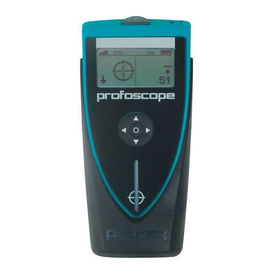
Overview of the Profoscope Display Navigation Reset Key Measurement Center (MC) LED Indicator Function Key On/Off Button Battery Compartment Center Line (CL) 10 Select Button Fig 1: Profoscope set up The Profoscope Display 11 Measuring Range (Standard, Auto) 13 14... -
Page 7: Tutorial
NOTE! Remove all metallic objects such as rings and watches before you start measuring. Calibrated Measuring with Profoscope The Profoscope is calibrated to measure on a normal rebar arrangement; which is an arrangement of non-stainless steel rebars fastened with binding wires only. E. g. when measuring on welded mesh wires the cover and diameter readings must be corrected (see 5.3.3 and 5.4.5). -
Page 8: The Measuring Range
The Measuring Range The pulse induction principle used by Profoscope has defined operating ranges and accuracies. The measuring range is dependent on the bar size. The expected accuracy of the cover measure- ment is indicated in the graphic below. (Complies with BS1881 part 204, for a single rebar with sufficient spacing and known diameter). - Page 9 NOTE! In case the diameter is not known and cannot be measured the rebars should be exposed in one area to set the correct diameter in the Profoscope. With the correct diameter set the cover over a single rebar can be measured with the accuracy shown in chapter 3.3.
- Page 10 >150 mm ” >6 : 130 mm / 5.2” without Neighboring rebar correction 50 mm / 2.0” with Neighboring rebar correction (see 5.4.2) Fig 8: Minimum rebar spacing for correct readings © 2015 Proceq SA...
-
Page 11: Getting Started
Fig 10: Reset Hold the Profoscope in free space (no metal within a 200 mm / 8” sphere) and press the Reset Key . A circular arrow rotates on the display for approximately 2.5 seconds while the reset is car- ried out. -
Page 12: Performing A Real Test
Performing a Real Test Read the Understanding the limits of the pulse induction principle Tutorial Complete Check the operation of your Profoscope with the Getting Started start-up test kit Regional Settings Change default settings to your regional standard What do you ... -
Page 13: Locate A Rebar
It is important to be able to distinguish between the two situations. 5.2.1 Finding a Rebar Place the Profoscope on the test surface and move it slowly in a chosen direction. The Profoscope reacts differently depending on its orientation relative to the rebars. There are three scenarios. - Page 14 Center Line (9) Fig 14: Rebar centered Approaching a Midpoint The Rifle Scope moves in the same direction as the Profoscope. The signal strength is decreasing as the Rifle Scope moves towards the Center Line (9). MC (4) Fig 15: Approaching a mid point Continue sweeping until the Rifle Scope is exactly at the Center Line (9).
- Page 15 Little or no movement of the Rifle Scope. Fig 18: Rifle close to the Center Line (9) In this case turn the Profoscope by 90° and continue sweeping as described under Scenario A) above. © 2015 Proceq SA...
- Page 16 Position the Profoscope with the lower edge (LED output) of the Center Line (9) at the center point of the rebar. Rotate the Profoscope around this center point either from left (L) or right (R). It will light up once the Center Line (9) is precisely over and parallel to the rebar. Mark the position of the Center Line (9) at the display side of the Profoscope.
- Page 17 • When locating the second layer (e. g. in a column the vertical rebars are the second layer) hold the Profoscope with the Center Line (9) perpendicular to the rebars of the first layer (e. g. in a column hold it vertical). Now move the instrument with the MC (4) along the midpoint line of two first layer rebars parallel to direction of the first layer (e.
-
Page 18: Measure Cover Depth
But this is only possible to a maximum cover of 60 mm to 65 mm / 2.5” to 2.6”. Now you can set the measured diameter. Read the Cover Depth Place the centre line of the Profoscope directly over the rebar and read off the cover depth. e. g. Cover depth = 15 mm MC (4) - Page 19 However, the accuracy of the cover measurement can drastically be increased by setting the meas- ured diameter in the Profoscope prior to the measurements. In case the diameter can not be meas- ured the rebars should be exposed in one area. The diameter to be set is in general 1.4 times the real diameter of a single bar.
- Page 20 For some common arrangements you may refer to the Excel-Macro “Cover Measurement at Stir- rups” on our website www.proceq.com under Profoscope. NOTE! In all other cases the first layer rebar must be exposed on some spots to deter- mine the real cover and compare it with the Profoscope readings. © 2015 Proceq SA...
- Page 21 Move the Profoscope over the test surface. Whenever the cover depth is less than the programmed minimum the LED Indicator will light and if it is enabled, an acoustic alarm will be given.
-
Page 22: Measure Rebar Diameter
Steps 1 and 2 until a rebar is located with the required spacing to a neighboring rebar. Step 4 Place the MC (4) of the Profoscope over the rebar at the midpoint line of the rebars run- ning crosswise to the rebar under test and click the Function Key (6) on the left side. - Page 23 Step 4 Place the MC (4) of the Profoscope over the rebar at the midpoint line of the rebars run- ning crosswise to the rebar under test and click the Function Key (6) on the left side.
-
Page 24: Settings
Set this value into the Profoscope and proceed. 5.4.5 Diameter Measurements on Welded Reinforcement Meshes In most cases a diameter can be measured but the displayed value is far too high and cannot be used. -
Page 25: Regional Setting
Regional Setting The Profoscope supports four regional settings. This setting affects all other displays and should be done prior to making other selections. Metric Cover and bar diameters in mm according to table in 6.3 ASTM inch Cover in inch, bar diameters according to table in 6.3 ASTM mm Cover in mm, bar diameters according to table in 6.3... -
Page 26: Measuring Range Selection
< 80 mm < 3 inch *The Profoscope measures first in the “Auto Standard” range. It switches automatically from “Auto Standard” to “Auto Large” if the signal becomes too weak. The range “Standard” must be set, when measuring over welded wire meshes. -
Page 27: Neighboring Bar Compensation
For larger spacing the compensation is not necessary and the space value must be set to zero (-). Memory Function (for Profoscope+ only) Fig 32: Main menu icons of Profoscope+ Select memory card symbol to activate the data storage mode. Minimum cover function is auto- matically deactivated if the memory function is turned on. - Page 28 6.8.2 Automatic Storage Mode: This mode is used for surface scans. Position the Profoscope with the Center Line (9) parallel to the rebars of which the cover will be stored. Press the Function Key (6) and start moving sidewise over the rebars.
-
Page 29: Technical Specifications
120 s Environmental Conditions Temperature range -10º to 60º C / 14º to 140º F Humidity range 0 to 100% rH IP classification IP54 Conformity CE, RoHS and WEEE Memory (for Profoscope+ only) Memory Capacity 49’500 Measurements © 2015 Proceq SA... -
Page 30: Standards And Guidelines
Standards and Guidelines Standards The Profoscope is designed according to the following standards: British: BS 1881 part 204, German: DIN1045 Swiss: SN 505 262 Guidelines The non-destructive rebar detection method is described in the German guide line B2 of the DGZfP (Deutsche Gesellschaft zum zerstörungsfreien Prüfen, German society of non destructive testing). -
Page 31: Maintenance And Support
In order to prevent abrasion the instrument is protected by a self-adhesive protective cover. It is recommended to check and replace this cover periodically. Remove the two AA-batteries when the Profoscope is not used for longer periods to prevent dam- ages due to battery leakage. -
Page 32: Data Management And File Structure
Fig 39: Profolinke Menu “Device” Select the menu “delete all objects” to delete all data stored on Profoscope+. This will delete all objects and cannot be undone. Fig 40: Profolink Menu “File” “Add” function synchronizes data between PC and Profoscope+. In addition, locally stored data files can be added to an existing project. - Page 33 Notes © 2015 Proceq SA...
- Page 34 Notes © 2015 Proceq SA...
- Page 35 Notes © 2015 Proceq SA...
- Page 36 Zhao Jia Bang Road Shanghai 200032 Phone +86 21-63177479 +86 21 63175015 info-china@proceq.com Subject to change. Copyright © 2015 by Proceq SA, Schwerzenbach. All rights reserved. Part Number: 82039101E ver 10 2015, Firmware Version 3.0.1, Profolink Version 1.0.1 © 2015 Proceq SA...
Need help?
Do you have a question about the PROFOSCOPE and is the answer not in the manual?
Questions and answers