Table of Contents
Advertisement
Quick Links
Advertisement
Table of Contents

Related Manuals for Siare Falco 202


Summary of Contents for Siare Falco 202
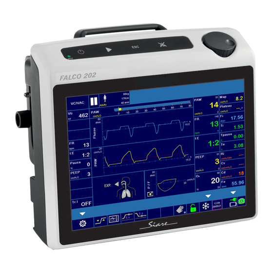
- Page 1 Falco 202 Lung ventilator turbine-driven ventilation User manual...
-
Page 3: General Information
Engineering International Group s.r.l. concerning the Falco 202 lung ventilator and its use is limited to what is indicated in the guarantee supplied. The contents of this manual do not in any way limit the right of SIARE Engineering International Group s.r.l. to revise, change or modify without prior notice the equipment (including the relative software) described herein. -
Page 4: Observations
We would be grateful if you would send us your comments (see address at page IX). The SIARE trademark is used throughout this manual as an abbreviation for the manufacturer: SIARE Engineering International Group s.r.l. -
Page 5: Warnings, Cautions And Notes
You are advised to carefully read the information given alongside the three symbols shown on the previous page, since it contains considerations on the safety, the special requirements for the use Falco 202 lung ventilator (hereinafter called ventilator) and the relative safety regulations. - Page 6 SIARE recommends establishing a maintenance and service contract with SIARE or the local authorised service dealer in order to guarantee the scheduled maintenance required to operate the ventilator in a safe and correct manner. To prevent the risk of fire, keep the ventilator and/or the oxygen tubes away from matches, lit cigarettes and inflammable material, such as anaesthetic gases and/or sources of heat.
- Page 7 The correct functioning of the ventilator can be impaired if original SIARE spare parts and accessories are not used; the use of other accessories is however allowed only if formally authorised by SIARE in accordance with current safety regulations.
- Page 8 Before starting the ventilator use, you have to carry out the preliminary checks. WARNING !! Before connecting the ventilator to other electrical equipment not described in this manual, a request for authorisation should be sent to Siare. WARNING !! Qualified staff must make the regulation of ventilation parameters. WARNING !! An auxiliary ventilation system is suggested for the patients for which the ventilator represents a life support.
-
Page 9: Year Of Manufacture
Shelf life of medical device The Directive 93/42EEC on medical devices foresees that the manufacturer defines the shelf life of the device according to the intended purpose. The shelf life foreseen by SIARE for the lung ventilator model Falco 202 is 10 years. Manufacturer SIARE Engineering International Group s.r.l. -
Page 10: Electromagnetic Compatibility
The Falco 202 lung ventilator is designed to operate in the specified electromagnetic environment (see warning below). The customer or the user of Falco 202 lung ventilator should ensure that it is used in such an electromagnetic environment. The ventilator complies with the EN 60601-1-2 regulations... -
Page 11: Table Of Contents
1.3.1 Graphic user interface (GUI) ..............1-3 1.3.2 Electronics and driving ................1-4 1.3.3 Pneumatics ....................1-4 Correct operation ....................1-4 1.4.1 Use of Falco 202 Evo ................1-5 Norms and standards regulations................ 1-6 DESCRIPTION ......................2-1 Side view ......................2-3 Power supply area .................... - Page 12 User manual, DU322210210...
- Page 13 3.4.2 Ventilator switch-on / “ SELF TEST “ phase ........... 3-14 Turn the lung ventilator OFF ................3-18 Preliminary checks – Introduction ..............3-19 3.6.1 Preliminary checks - TESTS ON DEMAND ........... 3-19 3.6.2 O2 Sensor calibration ................3-21 3.6.3 Exit from TESTS ON DEMAND ............. 3-24 XIII Falco 202...
- Page 14 3.6.4 Preliminary checks - Lung Ventilator ............3-25 3.6.5 Preliminary checks - Parameters monitoring .......... 3-27 3.6.6 Preliminary checks – Alarms ..............3-28 3.6.7 Alarms check ..................3-30 3.6.8 Conclusions ................... 3-32 List of preliminary checks .................. 3-33 “ TESTS ON DEMAND “ ................... 3-34 3.8.1 Turbine Characterization ...............
- Page 15 4.13.4 Expiratory flow sensors calibration ............58 4.13.5 VTEc ( ON – OFF ) ................... 60 4.13.6 Trend and Events ..................61 4.13.7 Setting IRMA / ISA the RS-232 port is able to detect the EtCO2 sensor. .. 61 4.13.8 Exit ......................62 Falco 202...
- Page 16 ALARMS ........................5-1 Displaying and used symbols ................5-2 5.1.1 Alarms display area ................. 5-2 5.1.2 A1 - Alarm area ..................5-3 5.1.3 A2 - MAIN MENU / ALARMS parameters ..........5-5 5.1.4 A3 - General information area ..............5-6 5.1.5 A4 - Acoustic alarm silencing ..............
- Page 17 Technical sheet ....................A-1 Preliminary checks ....................A-9 Glossary......................A-11 EMC tables - Guidance and manufacturer’s declaration ........A-15 A.4.1 Table 1 ....................A-15 A.4.2 Table 2 ....................A-16 A.4.3 Table 3 ....................A-17 A.4.4 Table 4 ....................A-18 XVII Falco 202...
- Page 18 This page has been added to make front / back copy easier. XVIII User manual, DU322210210...
-
Page 19: Introduction
“foolproof”, in this way there is no margin for the user to make incorrect or inadequate manoeuvres. The new Falco 202 lung ventilator is very different from all the previous versions and it has been conceived for the using in Intensive Care, Emergency and Transport. Even the maintenance procedures have been simplified and the parts subject to wear or deterioration have substantially decreased. -
Page 20: Main Innovations
Main innovations The new 2 generation of lung ventilators Falco 202 combines aesthetic and reliability in an ergonomic structure which permit to the device to be easy to use and easy to understand. 1.2.1 Automatic compensation of all ventilation parameters ... -
Page 21: Small And Powerful
Dimensions, 290 x 245 x 215 mm (W x H x D) and light weight 5.5 Kg. These special features permit to the Falco 202 to be handy and easy to use in small spaces even during transport. 1.2.6 Battery ... -
Page 22: Electronics And Driving
(see on chapter 2). The Falco 202 incorporates a series of sensors for continuous patient monitoring, the most important of which are: ... - Page 23 1.4.1 Use of Falco 202 The use of Falco 202 lung ventilator is simple and intuitive for the persons familiarised with resuscitation ventilators, a short training course is in enough to learn how to use it.
-
Page 24: Norms And Standards Regulations
Norms and standards regulations The Falco 202 lung ventilator is made in accordance with the following norms (and following updates) and it is manufactured according to UNI EN ISO 13485:2004 standards. EN 60601-1:2006/ A1:2011/ A1:2013 Medical electrical equipment - Part 1: General requirements for safety. -
Page 25: Description
DESCRIPTION This section of the user manual features the main parts and components of the Falco 202 lung ventilator for Intensive Care, Emergency and Transport (hereinafter called ventilator) and some of its most used functionalities. With regard to the assembly, the interface and the servicing operations, please refer to the relative chapter or contact Siare technical support service. - Page 26 Falco 202 - rear view see 2.1 Side view see 2.2 Power supply area Pneumatic area ( low O pressure ) see 2.3 Patient connections see 2.4 see 2.5 Keyboard with soft keys and encoder knob see 2.6 9” LED display see 2.7...
-
Page 27: Side View
Side view AIR FILTER : turbine air filter connection (see next chapter) Air intake RS-232 connector ( ODU connector ) : CO sensor connection or Trend and Events downloading Electric power supply (please, refer to next paragraph) Falco 202... -
Page 28: Power Supply Area
The external supply voltage can be provided trough a battery or a supply source having the characteristics specified above. An external battery used as power source for the functioning of the Falco 202 become integral part of this medical system. I / O : ventilator supply switch ... -
Page 29: Patient Connections
V.EXP (option) : unused fitting O2 (LOW PRESSURE) : medical oxygen connection from a low pressure source WARNING !! LOW PRESSURE : low O2 pressure source, max flow 15 l/min. INSP. TO PATIENT : inhalation fitting for patient circuit Transport handle Falco 202... -
Page 30: Keyboard With Soft Keys And Encoder Knob
Keyboard with soft keys and encoder knob A control keyboard and an encoder knob are available on the upper side of the ventilator. These components allow quick and easy use of the Falco 202 lung ventilator (referred to from now on as ventilator). - Page 31 In order to edit other parameters: turn the encoder knob clockwise (anticlockwise). Press the ESC soft keys to go back to STAND-BY display. The system automatically returns to STAND-BY or ventilator operation display. Falco 202...
-
Page 32: Soft Keys: Use
2.4.2 Soft keys: use ALARM RESET Press this key to silence the acoustic warning of an active alarm. After removing the alarm cause, press this key once again to cancel the visual warning displayed on the screen. Press this key to exit the “current” screen and return to the “previous” one. -
Page 33: 9" Led Display
9” LED display On the front side of Falco 202 lung ventilator for Intensive Care, Emergency and Transport (referred to from now on as ventilator) is a 9” LED display that will show all information necessary for patient ventilation. The main featured information are: operating mode selection, respiratory parameters setup and display, visual and acoustic alarm warnings. - Page 34 Select the MENU function to view the MAIN MENU (please see 2.7). Select the SET function to view/edit the operating mode and all the relative physiological respiratory parameters (PRP). (SET function: please refer to the note on the following page). 2-10 User manual, DU3222102...
- Page 35 (please see 2.6.5 or 4.10). By enabling this function you can also see the additional respiratory parameters (if necessary). This function is available only when the ventilation is active; please see 4.10. 2-11 Falco 202...
- Page 36 “Forced inspiration hold” function. By activating this function, the system will extend the inspiration time, from 5 up to 15 seconds. “Forced expiration hold” function. By activating this function, the system will extend the expiration time from 5 up to 10 seconds. “Manual”...
-
Page 37: Respiratory Parameters Monitoring
PRP, and they are only informative, they do not refer to real clinical cases. The light bar indicator (with scale from -20 to 80 cmH displays the pressure inside the airways during the respiratory phase, in real time. 2-13 Falco 202... - Page 38 The value displayed is the maximum measured pressure inside the airways (cmH The displayed value shows the positive pressure at the end of the expiration: the measurement unit is cmH The clinician can control if the ventilator is able to reach and keep the PEEP pressure level set, using this value.
-
Page 39: Operative Mode
(Apnea Back-Up) with leak compensation. (Volume Targeted) Pressure support ventilation with assured current volume and assured safety respiratory rate set by the clinician (Apnea Back-Up). Volume targeted controlled ventilation synchronised with the patient if the inspiratory trigger is activated. 2-15 Falco 202... - Page 40 Volume-targeted synchronised intermittent mandatory ventilation. Pressure-targeted synchronised intermittent mandatory ventilation. Continuous Positive Airway Pressure applied on the airways with granted respiratory rate set by the clinician (Apnea Back-Up) with leak compensation. After selecting the most suitable operative mode for patient ventilation, the system will automatically display the physiological respiratory parameters for the new setup.
-
Page 41: Alarm Signals Area
You can edit the alarm settings (SET - MENU - ALARMS) even when they are active. After editing the alarm settings, the relative signal will remain active and the status icon will blink for a pre-set time. 2-17 Falco 202... -
Page 42: Graphic Area
ALARM SILENCING Press the ALARM RESET key to interrupt the acoustic signal for a pre- set period of time. During the silencing period, the text of the alarm will still be displayed. Press the ALARM RESET key once again to delete the alarm text, only if the alarm activation condition is no longer present. - Page 43 The measured Leak value should be adequate to the active ventilation type (volumetric or pressometric) and within the tolerances of the local norms. Oxygen consumption calculation The oxygen consumption value in L/min is displayed after one minute and in case of oxygen set value higher than 21% . 2-19 Falco 202...
-
Page 44: Graphic View : Lungs Icon
2.5.6 Graphic view : lungs icon The lung ventilator is equipped with tools for detecting and monitoring the breathing phases. A suitable lung icon simulates the patient's lungs, graphically displaying the respiratory cycle by alternatively switching the lungs color. The lung icon is particularly meaningful for quick patient breathing monitoring. -
Page 45: Additional Respiratory Parameters
PRP, and they are only informative, they do not refer to real clinical cases (please see 4.8.15). It shows the average calculated pressure for the airways: the unit of measurement is cmH It shows the plateau pressure: the unit of measurement is 2-21 Falco 202... - Page 46 The flow sensor installed on the inspiratory line measures the maximum inhaled flow value (measured in L/min) and the value is displayed on the screen. It shows the duration of the patient's inspiratory phase: the unit of measurement is second. It shows the duration of the patient's inspiratory standby phase: the unit of measurement is second It shows the duration of the patient's expiratory phase: the unit...
-
Page 47: General Informations
Mains power supply status indication (please see cfr. 5) The date and time can be set using the encoder knob. For the keyboard with soft keys and encoder knob methodology of use, please see chapter 2.5. 2-23 Falco 202... -
Page 48: Main Menu
MAIN MENU area to set the basic functions for proper ventilator operation. Before using the Falco 202 lung ventilator for Intensive Care, Emergency and Transport, please use the MENU function to set all necessary items for proper ventilator operation. - Page 49 (please see cfr. 4.5). The clinician can delete the previous data before a new ventilation (please see cfr. 4.6). The clinician can restore the default parameters: factory set (please see cfr. 4.11.7). Back to MAIN MENU. 2-25 Falco 202...
-
Page 50: Product Identification Label
Product identification label The product identification label mentions the following information. Manufacturer Model name Main power supply Battery’s features Fuses features Regulation (CE mark) Serial number Symbols (see description) The mark identifies the protection level against electric shock (category of protection type BF). -
Page 51: Preparation For Use
PREPARATION FOR USE The first section of this chapter describes the installation procedures for the Falco 202 lung ventilator for Intensive Care, Emergency and Transport (hereinafter called ventilator); the second section highlights the preliminary checks to be carried out before using Falco 202. - Page 52 WARNING !! Patient/clinician injury hazard The device and all its accessories should be mounted and connected by highly qualified technical staff, suitably trained and authorised by SIARE. Do not connect or disconnect parts or components of the ventilator when it is on or powered.
-
Page 53: Before Use
FiO 2 ]. WARNING !! Patient injury hazard When the ventilator is on, the system carries out a series of checks, such as including the O 2 sensor connection ( “SELF TEST” phase see cfr. 4.2.1 ). Falco 202... -
Page 54: Battery Recharge
3.2.2 Battery recharge • The ventilator is provided with a battery (NiMh 12Vdc / 4,2Ah) that ensures its operation for at least 4 hours (if in perfect condition; 3 hours, depending on the ventilation parameters), in case the mains power supply is cut off. •... -
Page 55: Preparation For Use
A medical use. WARNING !! Patient/clinician injury hazard SIARE specialized personnel or qualified technical personnel formerly authorized by SIARE, shall always verify the following during the installation: • the presence of the ground cable in the electric plug used to connect the device. - Page 56 WARNING !! Personal injury - physical hazard In order to avoid any electric shock hazard, make sure that the supply cable is connected to an electrical socket with the grounding cable connected. • The lung ventilator complies with the requirements for electro-medical devices detailed on chapter 1.5 ( Norms and standards regulations ).
-
Page 57: Protection Fuses
Fuse replacing WARNING !! Patient/clinician injury hazard The operations described below must be carried out only by highly qualified staff, specifically trained and authorised by SIARE. If a protection fuse breaks, please proceed as follows. • Cut off mains power supply •... -
Page 58: Patient Circuit Connection
3.3.3 Patient circuit connection • Connect the patient circuit to INSP. TO PATIENT connector and to flow sensor (patient expiratory line). Current volume Tubes set Use a patient circuit suitable for the patient you want to from 50 to 200 mL paediatric treat. -
Page 59: Use Of Antibacterial Filters
3.3.5 Data Connection (Trend and Events downloading ) Connect the interface cable to the ODU connector (RS-232) and to a PC serial port. A dedicated software permits the download and the analysis of the data stored in the lung ventilator. Falco 202... -
Page 60: Five Wheels Support
3.3.6 Five wheels support Assembly the trolley using the instructions supplied with the trolley. CAUTION Before positioning the ventilator, be sure that the trolley has been properly mounted, that the screws and bolts are well tighten and that the wheels move properly. -
Page 61: Connection Of Other Devices
3.3.7 Connection of other devices Connection of Siare devices In order to connect to the ventilator other devices manufactured by Siare, please refer to the connection instructions attached to this manual. WARNING !! Patient/clinician injury hazard Do not connect to the ventilator any external devices NOT manufactured or NOT authorised by SIARE (example: discharge systems, patient simulators, etc…..), and that are not described in this user manual. -
Page 62: Lung Ventilator Use
, if necessary) and electrical power supply • connected to a patient simulator at the provided patient circuit terminal. For tests and checks, please use the patient simulator SIARE cod. LS.AB.001 that is equipped with variable resistance and compliance. 3-12... - Page 63 Do not use the ventilator if you detect any suspect oxygen leaks from the ventilator or any other unit next to it. Close all oxygen supply sources and contact the nearest Siare Support Centre or any other support centres authorised by Siare.
-
Page 64: Ventilator Switch-On / " Self Test " Phase
3.4.2 Ventilator switch-on / “ SELF TEST “ phase • Set the main switch (placed on the back of the ventilator) to “I”. • Make sure that on the ventilator keyboard (commands area) the green led (that indicates the presence of mains power supply) is on. •... - Page 65 The clinician should check if the system generates the acoustic signal, he can confirm the test by silencing the alarm. For a more correct and detailed analysis of the issues arising during “ SELF TEST “ phase, please consult the Service Manual. 3-15 Falco 202...
- Page 66 WARNING !! Patient/clinician injury hazard The “ SELF TEST “ phase did not complete successfully. Please see chapter 5 and contact the nearest Siare Support Centre or any other support centres authorised by Siare. However, the system allows you to proceed. Press START.
- Page 67 • In this mode you can set and/or edit all ventilator parameters and alarms limit relative to the operating mode that you will use on the patient that you want to treat. 3-17 Falco 202...
-
Page 68: Turn The Lung Ventilator Off
Turn the lung ventilator OFF • STAND-BY operating mode. • Hold the ON-OFF key for few seconds to turn the ventilator OFF. • Turn the lung ventilator OFF. • Press NO: the ventilator goes back to STAND-BY operating mode. • Press YES: the lung ventilator turns OFF. -
Page 69: Preliminary Checks - Introduction
Ventilator ON : STAND-BY operating mode. 3.6.1 Preliminary checks - TESTS ON DEMAND To carry out the TESTS ON DEMAND you must know the keyboard operating mode and the options available in the ventilator MENU (please see chapter 2). 3-19 Falco 202... - Page 70 • Press and turn the encoder knob (referred to from now on as knob) until activating the MENU function. • MENU function active: press the knob. • The system will display the MAIN MENU screen, SETUP parameters. • SETUP function active: press the knob.
-
Page 71: O2 Sensor Calibration
WARNING !! Ventilator malfunctions risk This procedure should be carried out to check the proper operation of the O sensor. • To avoid any patient injury risks, carry out this procedure monthly. • TESTS ON DEMAND. O sensor calibration screen. 3-21 Falco 202... - Page 72 • Press the knob; the system will activate the O sensor calibration. • Close the patient circuit (close manually the patient connector). • Press START to start the procedure. • Oxygen sensor calibration procedure in progress. NOTE. To check if the O sensor works properly, the software reads the electrical value (mV) generated...
- Page 73 TESTS ON DEMAND FAILED If the system does not exceed the preliminary checks phase, please see chapter Alarms - Trouble Shooting or contact the nearest Siare Support Centre or any other support centres authorised by Siare. 3-23 Falco 202...
-
Page 74: Exit From Tests On Demand
3.6.3 Exit from TESTS ON DEMAND • Turn the knob to select the option: Exit. Exit TESTS ON DEMAND • Press the encoder knob to exit from the TESTS ON DEMAND screen. • Press the ESC soft key: the system will leave the TESTS ON DEMAND screen. -
Page 75: Preliminary Checks - Lung Ventilator
In order to carry out the preliminary checks, proceed as follows. 1) Ventilator in STAND-BY. 2) Select and operating mode (VC- VAC). • Press the knob: the system will activate the SET function. • Press the knob once again: the system will display the respiratory parameters. 3-25 Falco 202... - Page 76 Pause OFF, 5, 10 cmH2O PEEP 4) Press the START button: the ventilator begins its cycle. For tests and checks, please use the patient simulator SIARE cod. LS.AB.001 that is equipped with variable resistance and compliance. 3-26 User manual, DU322210210...
-
Page 77: Preliminary Checks - Parameters Monitoring
O, 1 L/min • : 60% 7) Check the correspondence between the monitored parameters and the displayed curves. Note: Oxygen consumption calculation The oxygen consumption value is showed in L/min for oxygen settings of more than 21%. 3-27 Falco 202... -
Page 78: Preliminary Checks - Alarms
Ventilator operation check • Make sure that the airways pressure increases during the inspiratory phase. • Make sure that the airways limit pressure intervenes (pressometric operating mode). • Make sure that the variation in the set oxygen concentration value (O 2 %) corresponds. - Page 79 • Press the knob to confirm the modification of the alarm value. Exit the ALARMS screen • Press the ESC soft key; the system will leave the ALARMS screen. • After about 60 seconds the system automatically returns to STAND-BY or ventilator operation display. 3-29 Falco 202...
-
Page 80: Alarms Check
3.6.7 Alarms check WARNING !! Severe patient injuries The alarms must trigger at the proper time and in the correct manner. Check the proper activation of the visual and acoustic signals. Before starting the alarm checking: • check the alarms setup, and change the set values whenever necessary (please see previous paragraph) •... - Page 81 During ventilation, set the main power supply switch to OFF ( 0 ). • The system activates the mains power failure alarm: silence the POWER SUPPLY alarm. FAULT • Restore the main switch and set it to ON ( I ). 3-31 Falco 202...
-
Page 82: Conclusions
If the ventilator is in STAND-BY the alarms are not active. 3.6.8 Conclusions Carry out all preliminary checks and make sure that they were completed successfully before connecting the patient to the lung ventilator Falco 202. Preliminary checks phase failed. •... -
Page 83: List Of Preliminary Checks
Exit from TESTS ON DEMAND 3-28 3.6.4 Preliminary checks - TESTS ON DEMAND 3-30 3.6.5 Preliminary checks - Parameters monitoring 3-31 3.6.6 Preliminary checks - Alarms 3-33 3.6.7 Alarms check 3-35 3.6.8 Conclusions 3-36 List of preliminary checks 3-36 3-33 Falco 202... -
Page 84: Tests On Demand
“ TESTS ON DEMAND “ WARNING !! Patient / operator injury hazard The procedures described are critical operations and must be carried out only by authorised staff as they might affect the lung ventilator safety and proper operation. To display the TEST ON DEMAND screen, press and turn the encoder knob (referred to from now on as knob) until activating the MENU function. - Page 85 • Turn the knob to activate the parameters: Press the knob selecting, TESTS ON DEMAND. The TESTS ON DEMAND screen appears. 3-35 Falco 202...
-
Page 86: Turbine Characterization
3.8.1 Turbine Characterization In order to start the Turbine characterization (calibration) program is necessary the intervention of qualified SIARE personnel or qualified technical personnel authorized by SIARE. The turbine characterization calibration is necessary in the following cases: • when you note differences out of tolerance (more than 2% of the end of the scale +... - Page 87 “Test Failed “ message. TEST FAILED If the system fails the test, please see chapter Alarms - Trouble Shooting or contact the nearest Siare Support Centre or any other support centres authorised by Siare. 3-37 Falco 202...
-
Page 88: Expiratory Flow Sensors Calibration
3.8.2 Expiratory flow sensors calibration In order to start the Expiratory Flow Sensors Calibration program is necessary the intervention of qualified SIARE personnel or qualified technical personnel authorized by SIARE. The Expiratory Flow Sensors Calibration is necessary in the following cases: •... - Page 89 Close the patient circuit. • Press START: the expiratory flow sensors calibration starts • The expiratory flow sensors calibration is in progress. Note. Press ESC: the calibration stops and the system shows the “ Test Aborted “ message 3-39 Falco 202...
-
Page 90: O2 Sensor Calibration
TEST ABORTED If the system fails the test, please see chapter Alarms - Trouble Shooting or contact the nearest Siare Support Centre or any other support centres authorised by Siare. At the end of the Expiratory flow sensors calibration the system come back to the MAIN MENU. -
Page 91: Exit From Tests On Demand
Turn the knob to select the option: Exit. Exit TESTS ON DEMAND • Press the encoder knob to exit from the TESTS ON DEMAND screen. • Press the ESC soft key: the system will leave the TESTS ON DEMAND screen. 3-41 Falco 202... - Page 92 This page has been added to make front / back copy easier. 3-42 User manual, DU322210210...
-
Page 93: Lung Ventilator Use
LUNG VENTILATOR USE This chapter shows you how to use the Falco 202 lung ventilator for intensive care, emergency and transport (referred to from now on as ventilator). Thoroughly read this chapter and the entire manual to make sure respiratory parameters and alarm limits are set correctly and choose the most suitable ventilation mode. -
Page 94: Stand-By Mode
STAND-BY mode 4.2.1 “ SELF TEST “ phase Set Cap4-1_Use_980222_UE_rev1 the main switch (placed on the back of the ventilator) to “I”. Make sure that on the ventilator keyboard (commands area), the green led (that indicates the presence of mains power supply) is on. ... - Page 95 After the “ SELF TEST “ phase is completed, press ESC to go to TESTS ON DEMAND. After the “ SELF TEST “ phase is completed, press START to go to STAND-BY mode. STAND-BY operating mode. Falco 202...
-
Page 96: Keyboard With Soft Key And Encoder Knob Use
TESTS ON DEMAND By means of this function it is possible to: calibrate the turbine calibrate the expiratory flow sensor calibrate the O Sensor perform the zeroing of Gas Analyzer (optional device) STAND-BY After carrying out the SELF TEST or before turning the ventilator off, it automatically switches to this operating mode. -
Page 97: Choice Of The Patient Type
Press the encoder knob to confirm your choice. The system will display the PATIENT TYPE screen choice ( ADULT, PAEDIATRIC, NEONATAL ). Turn and press the encoder knob to select the PATIENT TYPE. Falco 202... - Page 98 Below the Operative Mode acronym, the PATIENT TYPE set is specified: ADULT. When setting the PATIENT TYPE, the relevant default respiratory parameters and alarms limits are also automatically set. Press the encoder knob to confirm your choice. ...
-
Page 99: Setting Up The Menu Language
Press the knob to confirm your choice. The system will display the MAIN MENU screen, SETUP parameters. Press the knob to confirm your choice. The system will display the SETUP screen, LANGUAGE - Italian option. Falco 202... -
Page 100: Setup Screen Parameters Editing Procedure
To change the MENU language proceed as described herein (see cfr. 2.4): press the encoder to apply the Language change turn clockwise (anticlockwise) to select the desired language press the knob to confirm. The system will display the SETUP screen, LANGUAGE - English option... -
Page 101: Setting The Patient Data
The system will display the PATIENT DATA page. To exit PATIENT DATA screen. Press the ESC soft key. Select CLOSE option and press the encoder. Wait for the system to return to STAND-BY mode automatically. Falco 202... -
Page 102: Procedure For Setting The Patient Data
4.5.1 Procedure for setting the PATIENT DATA You can see below how to enter the patient name (this is shown only as an example). Use the encoder knob to enter the patient's identification data. The fields for entering the name and surname have a limit of 14 characters. The lower-case letters are placed after the upper-case letters. - Page 103 Press the ESC soft key to exit a patient identification data field, without scrolling through all available character spaces. Press the PATIENT DATA ERASE function to delete the patient identification data saved in the system. 4-11 Falco 202...
-
Page 104: Erasing The Patient Data
Erasing the PATIENT DATA Ventilator in STAND-BY operating mode. Press the encoder knob: the system will activate the SET function. Turn and select the MENU function. Press the knob to confirm your choice. The system will display the MAIN MENU screen, SETUP parameters. -
Page 105: Setting Up The Alarms
Turn the knob to select the option ALARMS. Press the knob to confirm your choice. The system will display the ALARMS page. For ALARMS parameters and limits setup, please see on 5.2 ALARMS setup. 4-13 Falco 202... -
Page 106: Operating Modes And Prp Parameters
In the following chapter you will find a description of available physiological respiratory parameters (referred to from now on as PRP) and the operating modes selectable on Falco 202 lung ventilator. WARNING !! Patient injury hazard Thoroughly read this chapter and the entire user’s manual to make sure you set the PRP correctly and choose the most suitable ventilation mode. -
Page 107: Niv Apcv ( Apcv )
During the inspiratory phase, the ventilator generates a settable flow (Slope). When the airway pressure reaches the control value (Pinsp), this pressure level is kept constant by the ventilator until the end of the inspiration that you can set using (RR). 4-15 Falco 202... - Page 108 Use the settable parameters to define an inspiratory trigger (Tr. I) used to set a flow expressed in litres per minute (or a pressure in cmH2O) that represents the limit for detecting the patient's spontaneous breathing attempt. The greater the value, the greater the patient's effort to breath. If the pressure set is not reached, make sure that the patient circuit is perfectly sealed and that the PRP parameters are properly set.
-
Page 109: Apcv-Tv
Use the settable parameters to define an inspiratory trigger (Tr. I) used to set a flow expressed in litres per minute (or a pressure in cmH2O) that represents the limit for detecting the patient's spontaneous breathing attempt. 4-17 Falco 202... - Page 110 The greater the value, the greater the patient's effort to breath. 4-18 User manual, DU322210210...
-
Page 111: Niv Psv ( Psv )
When the set support pressure is reached, the expiration takes the place of the inspiration (according to Tr. E - percentage of the inspiratory flow peak beyond which the expiration can begin). 4-19 Falco 202... - Page 112 This technique saves the patient from the work of breathing, as he only has to reach the small quota necessary to enable the ventilator trigger (Tr. I). This way, the respiratory rate depends on patient spontaneous activity and the current volume depends on set parameter values and patient patophysiological conditions.
-
Page 113: Psv-Tv
Therefore, the Tr. I parameter can’t be set to OFF. PSV-TV is a ventilation technique during which, at the beginning of the patient's spontaneous inspiratory effort, the ventilator provides support at an guaranteed volume (Vte) pre-set by the clinician. 4-21 Falco 202... - Page 114 When the Vte pre-set value is reached, the expiration takes the place of the inspiration (according to Tr. E - percentage of the inspiratory flow peak beyond which the expiration can begin). This technique saves the patient from the work of breathing, as he only has to reach the small quota necessary to enable the ventilator trigger (Tr.
-
Page 115: Vc-Vac
The patient's breathing attempt is detected by the system (Tr. I) and it automatically sends inside the airway a gas flow at a pre-set volume (Vti). 4-23 Falco 202... - Page 116 To combine the assisted mode with the control mode, the clinician must adjust the trigger sensitivity (Tr. I) at a value that suits the patient. If during the expiratory phase, the patient generates a spontaneous breath that activates the trigger, the ventilator will synchronise its activity to the patient's spontaneous breath, recalculating the I:E cycle times starting from that event and displaying them on the ventilator screen.
-
Page 117: V-Simv
Therefore, in SIMV mode, the ventilator can provide a combination of spontaneous and controlled breathing. SIMV mode is frequently used as a weaning ventilation mode from a fully controlled ventilation (completely depending on the ventilator) to an assisted ventilation mode. 4-25 Falco 202... - Page 118 The graphic shows how the SIMV operating mode works. The spontaneous activity between one synchronised breath and the other is 70% managed in pressometric mode (PS) while the remaining 30% represents the window for the activation of the forced synchronised breathing.
-
Page 119: P-Simv
Therefore, in SIMV mode, the ventilator can provide a combination of spontaneous and controlled breathing. SIMV mode is frequently used as a weaning ventilation mode from a fully controlled ventilation (completely depending on the ventilator) to an assisted ventilation mode. 4-27 Falco 202... - Page 120 The graphic shows how the SIMV operating mode works. The spontaneous activity between one synchronised breath and the other is 70% managed in pressometric mode (PS) while the remaining 30% represents the window for the activation of the forced synchronised breathing.
-
Page 121: Cpap
During the Apnea Back-up activation (in APCV ventilation), if you push the ALARM RESET button only the acoustic alarm is silenced. Then, the system will come back to CPAP ventilation only when the patient will be able to breath spontaneously. 4-29 Falco 202... -
Page 122: Man Operating Mode
4.8.10 MAN operating mode MANUAL ventilation available in all operating modes. By selecting the MAN mode using the encoder knob (at the bottom of the display) the system provides the patient with a breath. The breath ventilation parameters depend on the set operating mode. The function activation is monitored by the screen and signalled by the green LED inside the box, that turns on. -
Page 123: Physiological Respiratory Parameters ( Prp )
1 to 4. The value of 4 corresponds to the maximum turbine acceleration (depending also by the mechanical inertia). Ratio between inspiration and expiration phases. RR (bpm) Ventilator respiratory rate. RRsimv (bpm) Value of forced respiratory rate in SIMV mode. 4-31 Falco 202... - Page 124 Concentration percentage delivered to the patient can be set from 21% to 100% . Pause (%) Inspiratory pause time. The “inspiratory pause time” is displayed on the screen in % (% of the inspiratory time). It is also used to calculate the lung mechanics parameters (resistance and static compliance).
- Page 125 Tr. I (L/min) (cmH Flow level (pressure) for detecting the patient spontaneous breathing. Vte (ml) Expired tidal volume guaranteed for the patient. Vti (ml) Inspired tidal volume guaranteed for each breath. 4-33 Falco 202...
-
Page 126: Additional Respiratory Parameters
4.8.13 Additional respiratory parameters By selecting the GRAPHIC setup function using the encoder knob, the clinician can select and edit the curves, loops and additional parameters position. Mean airways pressure It shows the average calculated pressure for the airways: the unit of measurement is cmH2O. - Page 127 This measure, just like the previous one, is not related to specific alarms thresholds, it only provides information on the ventilation status. For additional ventilation parameters monitoring, please see 4.10. 4-35 Falco 202...
-
Page 128: Ventilation Phase
Ventilation phase Before starting the ventilation you have to: carry out all ventilator hardware connections (medical gases, power supply, patient circuit, ……..) carry out the preliminary checks (please see chapter 3.6) set the language and the patient data ... -
Page 129: Ventilation Interruption
To stop the ventilator, hold the ON-OFF key for several seconds. The system will ask whether to remain in STAND-BY or to shut down. Press the ENTER key to turn the ventilator off. Press the ON/OFF key : the ventilator returns to STAND- 4-37 Falco 202... -
Page 130: Graphical Settings And Operating Functions
4.10 Graphical settings and operating functions During the ventilation, the clinician can intervene using the graphical user interface, by selecting the options in the lower side on the screen. Select the MENU function using the encoder knob to access the ventilator's MAIN MENU (please see 4.11) where you can find all the functions displayed in the figure. - Page 131 To change the combination of GRAPHIC displayed on the screen, the ventilator must be on. Areas available on the display : 4 areas (frames) for the additional parameters and curves; 1 area (frame) for loops positioning. 4-39 Falco 202...
- Page 132 Press the knob to highlight the first frame. Turn the knob: the frames will be highlighted in sequence. Press the knob to confirm the frame modification. Turn the knob, the various types of curves will be displayed in sequence.
- Page 133 The breath ventilation parameters depend on the set operating mode. The function activation is monitored by the screen and signalled by the green LED inside the box, that turns on. This mode is active while the lung ventilator is running. 4-41 Falco 202...
-
Page 134: Main Menu
By selecting the MENU function you can view the MAIN MENU page and set the functions necessary for proper ventilator operation. Before using the Falco 202 lung ventilator for intensive care, emergency and transport, please use the MENU function to set all necessary items for proper ventilator operation. -
Page 135: Main Menu - Trends
4 minutes. Use the encoder knob to select the TRENDS box (the TRENDS box changes color). Press the knob, on the display will appear the page TRENDS. The yellow arrow show the active work area. 4-43 Falco 202... - Page 136 PRP curves (graphic), viewed in pairs. Vertical bar that shows the references movement in time. PRP, selectable in pairs. References over time on 72 hours with sampling at every 4 minutes. TRENDS view Press the knob: the parameters screen activates (turn the knob to choose the pair of parameters to monitor).
- Page 137 (e.g. Vm - PEEP): the system displays the trend of the parameters values. Press ESC to exit the TRENDS screen and go back to STAND-BY screen. Wait for the system to return to STAND-BY screen automatically. 4-45 Falco 202...
-
Page 138: Main Menu - Events
4.11.4 MAIN MENU – EVENTS Select the EVENTS function to monitor the information on the ventilator operation over time. The monitored event refer mainly to the alarms (active alarms) and the various operating conditions of the lung ventilator (POWER ON, POWER OFF, STAND-BY). The system can register up to 100 events, including the alarms. - Page 139 Turn the knob clockwise (anticlockwise) to view the EVENTS saved in the table. Press ESC to exit the EVENTS screen and go back to STAND-BY. Wait for the system to return to STAND-BY screen automatically. 4-47 Falco 202...
-
Page 140: Main Menu - Patient Data
4.11.5 MAIN MENU - PATIENT DATA To set the parameters in the patient data option please see 4.5 PATIENT DATA. 4.11.6 MAIN MENU - PATIENT DATA ERASE To delete the patient data, please see 4.6 PATIENT DATA ERASE. 4.11.7 MAIN MENU - DEFAULT PARAMETERS Select the DEFAULT PARAMETERS function to restore the lung ventilator DEFAULT PARAMETERS : ( Factory - SET ). -
Page 141: Main Menu - Close
Select the CLOSE box to exit the MAIN MENU and go back to STAND-BY view or to patient ventilation view. If the clinician does not select any function in the MAIN MENU the system returns automatically to the previous display. 4-49 Falco 202... -
Page 142: Main Menu - Setup
4.12 MAIN MENU – SETUP Select the MENU function to access the MAIN MENU screen and a series of functions such as SETUP, essential for setting up the ventilator operation. Use the encoder knob to select the MENU box (the MENU box changes color). -
Page 143: Setup Options In Main Menu
(PRF) and alarms (pre-set at factory) according to the Operative Mode selected ( see on cfr. 4.3). The PATIENT TYPE choice is showed on the display of the ventilator together with the selected Operative Mode. 4-51 Falco 202... - Page 144 Setting the time delay after which the APNEA BACK-UP support function activates. The time can be set from 5 to 60 sec. WARNING !! Patient injury hazard Pay utmost attention when setting this parameter as its incorrect regulation might seriously affect the patient: we recommend you to set this value at about 20 seconds.
- Page 145 Before using the ventilator on a patient, you have to carry out a series of preliminary checks to make sure that it works properly. Please see 3.8 for instructions regarding the TEST ON DEMAND function and how to use it. 4-53 Falco 202...
- Page 146 Not available. If you select the CLOSE option, the system will switch to MAIN MENU. 4.12.2 List of default parameters Parameters Adult Paediatric Neonatal VC/VAC APCV-TV NIV APCV Mode VT (ml) RR (bpm) Inspiratory Pause (%) Trigger (cmH2O) PEEP (cmH2O) FiO2 (%) Pinsp (cmH2O) Pmin (cmH2O)
-
Page 147: Calibratrion Programs
CAUTION The specialist SIARE staff or qualified technical staff, formally authorized by SIARE, must know the full content of this manual (and of the Service manual), before carrying out the operations described below. ... -
Page 148: Calibratrion Programs " Displaying
4.13.2 “ CALIBRATRION PROGRAMS “ displaying Set the main switch (placed on the back of the ventilator) to “I”. Make sure that on the ventilator keyboard (operator commands area) the green led (that indicates the presence of mains power supply) is on. ... -
Page 149: Turbine Characterization
CAUTION In order to start the Turbine characterization calibration program is necessary the intervention of qualified SIARE personnel or qualified technical personnel authorized by SIARE. For more information on the procedure please refer to the cfr. 3.8.1 and/or SERVICE manual. -
Page 150: Expiratory Flow Sensors Calibration
4.13.4 Expiratory flow sensors calibration The Expiratory flow sensors calibration is necessary in the following cases. Noted differences are more than 15% ( over 100ml ) between the set Volume value ( VTi - Vte ) and the expired Tidal Volume reading ( Vte ). ... - Page 151 In case of first calibration of ventilator, we suggest to execute this procedure after having checked the PEEP calibration and after performing a Turbine characterization (see 4.13.3). For more information please refer to the SERVICE manual. 4-59 Falco 202...
-
Page 152: Vtec ( On - Off )
4.13.5 VTEc ( ON – OFF ) The activation of VTEc ( VTEc ON ) function is necessary to optimize the displaying of calculation of the Vte parameter displayed during ventilator operation. Select Exit to go to the “ SELF TEST “ phase and escape from “... -
Page 153: Setting Irma / Isa The Rs-232 Port Is Able To Detect The Etco2 Sensor
4.13.7 Setting IRMA / ISA the RS-232 port is able to detect the EtCO2 sensor. Setting Trend and Events the RS-232 port is activated for the Falco 202 data downloading. Select Exit to go to the “ SELF TEST “ phase and escape from “ CALIBRATION PROGRAMS “ window. -
Page 154: Exit
4.13.8 Exit Select Exit to go to the “ SELF TEST “ phase and escape from “ CALIBRATION PROGRAMS “ window. The “ SELF TEST “ phase starts. 4-62 User manual, DU3222102... -
Page 155: Alarms
The parameters and the characteristics (activation time, presence or lack of an acoustic and/or luminous indicator) and the possible user’s actions respect to the alarm signals (silencing, suspend, inhibit) are described here below. Falco 202... -
Page 156: Displaying And Used Symbols
Displaying and used symbols Alarms display area 5.1.1 A1 - Alarm area: this area of the monitor provides the following indications. A string of text relevant to the type of active alarm. An “alarm bell” symbol which indicates the priority and the alarm state. A2 - MAIN MENU / ALARMS parameter. -
Page 157: A1 - Alarm Area
Low / High Exp. Vte Low / High Exp. VM Low / High PEEP Low / High FiO2 Gas Sensor: Low / High EtCO2 Power Failure Apnea time (configurable in MAIN MENU - SETUP area) Falco 202... - Page 158 Low Battery 50% Rem. Low Battery 25% Rem. Low Battery 10 Min. Rem. Battery Disconnected Battery Overtemperature (Patient) Circuit Disconnected Turbine Failure Turbine Over-Temperature Turbine Over-Current CAN-BUS Failure User manual, DU32221020...
-
Page 159: A2 - Main Menu / Alarms Parameters
The ventilators used in the same health environments can have different preset configurations of alarm limits. Verify that the preset alarm limits are appropriate for the new patient and adjust the alarm limits on values suitable to the new condition of use. Falco 202... -
Page 160: A3 - General Information Area
A3 - 5.1.4 General information area This area shows the battery charge level and the power supply status (present/absent). Green “BATTERY” symbol, indication of the battery charge level: − with fix symbol the battery is complete charge; − with flashing symbol the battery is in charging phase. Green “PLUG”... -
Page 161: A4 - Acoustic Alarm Silencing
Pushing further the RESET button will cancel the alarm text only if the alarm conditions is disappeared. If during the alarm silencing a new high priority alarm occur, the alarm silencing is cancelled and the acoustic signal and the visual texts are activated again. Falco 202... -
Page 162: Alarms Setting
Alarms setting Setting of ALARMS limits values 5.2.1 Before using the ventilator it is suggested to use the MENU function to adjust the items necessary for the correct operation of the equipment. During operation it is possible to adapt the alarm setting in function of the patient clinical situation. - Page 163 Turn clockwise (counter-clockwise) to select another alarm to be modified. Press the ESC soft key to return to the MAIN MENU. Wait for the system to return automatically to STAND-BY visualization. Press the ON-OFF key to return to STAND-BY visualization. Falco 202...
-
Page 164: Setting Of Alarms Volume
Setting of ALARMS volume 5.2.2 The Volume parameter allows the adjustment of the volume of acoustic alarms signals at any priority level. Press the encoder knob, the SET box is activated. Turn the encoder knob, select “MENU”. Press the knob to confirm; the “MAIN MENU” page is displayed. ... - Page 165 Turn clockwise (counter-clockwise) to increase (decrease). Press the knob to confirm. Press the ESC soft key to return to the MAIN MENU. Wait for the system to return automatically to the STAND-BY visualization. Press ON-OFF key to return to STAND-BY visualization. 5-11 Falco 202...
-
Page 166: Setting Of Default Values
Setting of DEFAULT values 5.2.3 The DEFAULT PARAMETER allows setting the standard factory parameters. Press the encoder knob, the SET function is activated Turn the encoder knob, select “MENU” , press the knob to confirm. The “MAIN MENU” page is displayed. -
Page 167: Alarms Default Values
10 - 30 Minute Volume (L) 2 - 12 1 - 8 1 - 4 PEEP (cmH 0 - 15 21 - 80 Power Failure Enable Apnea Time 20 sec (configurable in MAIN MENU – SETUP area) 5-13 Falco 202... -
Page 168: Troubleshooting
WARNING !! If the problem persists, carry out a complete check of the lung ventilator to identify any irregularities. If the problem cannot be resolved, contact the Siare Service Centre or a Centre authorized by Siare. Troubleshooting list 5.3.1 Switch ON failure The lung ventilator does not switch on. - Page 169 Switch the lung ventilator OFF and then switch back ON. If the problem persists, contact the Siare Service Centre or a Centre authorized by Siare. CAN-BUS failure This alarm condition occurs in case of system failure (electronic boards).
- Page 170 Check the battery connection. If the problem persists, contact the Siare Service Centre or a Centre authorised by Siare. Battery This alarm condition is present when the battery pack internal overtemperature temperature pass the 75°C. The ventilator go in STAND-BY mode.
- Page 171 If this is the case, eliminate the problem or replace them. Contact the Siare Service Centre or a Centre authorised by Siare. Min. Vte / VM This alarm condition occurs in case the Vte is lower than set value.
- Page 172 If the lung ventilator works properly check the flow sensor calibration and its connection with the device. Contact the Siare Service Centre or a Centre authorised by Siare. Low (High) PEEP This alarm condition occurs if the measured PEEP value is lower (higher) than the value set.
- Page 173 Check that nothing is limiting the patient's respiratory capacity. If the problem persists, contact the Siare Service Centre or a Centre authorised by Siare. PAW low In this condition, the patient circuit + patient system presents a lower resistance than expected or a higher compliance.
- Page 174 Check that the patient circuit is connected correctly to the lung ventilator and to the patient. If the problem persists, contact the Siare Service Centre or a Centre authorised by Siare. Apnea In this condition, no spontaneous respiratory activities is detected (RR = 0).
- Page 175 Replace the sensor and repeat the calibration. Contact the Siare Service Centre or a Centre authorised by Siare. Turbine over- The maximum safety level for the temperature (current) of the turbine temperature (over- is passed (100 - 105 °C).
-
Page 176: Maintenance
MAINTENANCE To guarantee the regular ventilator operation of the Falco 202 lung ventilator for intensive care, emergency and transport (hereinafter called ventilator), perform the following maintenance interventions with the recommended frequency. All interventions must be conform to the practice and protocols in force in each facility. -
Page 177: Cleaning, Disinfection And Sterilization
Siare is aware that working procedures can differ considerably from one health structure to another: it is therefore impossible to indicate specific procedures that are suitable for all requirements. -
Page 178: General Indications
Rinse the parts well with clean hot water (tap water can be used) and leave to dry. Siare recommends that the components should be checked every time they are cleaned and any damaged parts should be replaced. ... -
Page 179: Disinfection By Immersion (Chemical)
Do not disinfect, sterilize or re-use disposable products. Disinfect and sterilize every time an infected patient is ventilated. In normal conditions, disinfect and sterilize according to how often the ventilator is used and in any case at least once a month. ... -
Page 180: Cleaning, Disinfection And Sterilization Table
The patient circuit can be sterilized by means of steam but this can lead to early wear of the tubes. Yellowing and reduced flexibility are side effects caused by sterilization using steam. Falco 202... - Page 181 WARNING !! Risk of injury for the patient It is necessary to have at least one spare patient circuit in stock for routine use and /or accidental breaks. EXP V. Disinfect with steam or chemically. It is possible to sterilize the Monoblock component with gamma rays or ethylene oxide (ETO).
- Page 182 On the aim to guarantee patient and Perform daily checking’s of connections operator safety it is necessary to keep the cable condition; any damage, power supply cable in perfect conditions. also a minimum damage, must be promptly eliminated. Eventually replacing the whole cable. Falco 202...
-
Page 183: Periodic Maintenance
When you require service, please indicate the serial number of the unit and the problem to SIARE or to your authorised technicians. SIARE assumes responsibility for all provisions foreseen by the law, if the equipment is used and maintained as per the instructions in this manual and the technical manual ... - Page 184 The lung ventilator must also be inspected and checked in general and worn parts must be replaced, using the appropriate preventive maintenance kit. Use the appropriate preventive maintenance kit. Falco 202...
-
Page 185: Cleaning, Disinfection And Sterilization Before Use With Another Patient
All maintenance and/or repair operations require perfect knowledge of the ventilator and must therefore only be carried out by highly qualified personnel, specifically trained and formally authorised by SIARE. Inappropriate intervention or unauthorised modifications can compromise safety and cause danger to the patient. -
Page 186: Repairs And Spare Parts
SIARE. 6.3.1 Spare parts kit for lung ventilator Code : R20922000P1/GE Spare parts kit for annual maintenance to be used with the Falco 202, code 980222. Code : R209000CL Battery kit to be used with the Falco 202, code 980222. -
Page 187: Disposal
Disposal Batteries, accumulators, oxygen cells and electronic parts in general: do not put them in the fire, explosion risk do not open them, corrosion danger do not recharge batteries do not throw them away with normal waste. The batteries and the accumulators are special waste materials and they must be disposed of in appropriate containers in accordance with local regulations for the disposal of such waste materials. -
Page 188: Aannex
Falco 202 lung ventilator. Technical sheet GENERAL DATA Falco 202 is a lung ventilator conceived for use in home care and transport, with patients affected by respiratory diseases and it is suitable for ventilation of adult and paediatric patients. - Page 189 ENVIRONMENTAL CONDITIONS − Operating Relative humidity : 30 - 95% non-condensing − Temperature : from +10 to +40°C − Storage Relative humidity : < 95% − Temperature : from -25 to +70°C TECHNICAL DATA Dimensions (W x H x D) 290 x 245 x 215 mm Weight 5.5 Kg...
- Page 190 LUNG VENTILATOR FUNCTIONAL FEATURES Use destination Falco 202 is a lung ventilator for use in home care and transport with patients affected by respiratory diseases and it is suitable for ventilation of adult and paediatric patients. • Operation principle Time cycled at constant volume •...
- Page 191 Inspiratory ramp slope 1, 2, 3, 4 (acceleration slope) - (4 max. acceleration) (in operative modes by pressure only) PEEP From OFF, 2 to 50 cmH 2 O PEEP adjustment Microprocessor controlled valve O 2 concentration O 2 - Air mixture enrichment by O 2 inlet at low pressure Trigger detective method Through sensor (Pressure or Flow) Pressure trigger ( I ) Pressure adjustable from OFF;...
- Page 192 Default parameters SETUP parameters (setting) • Language • Graphic • Sound Volume • Energy Saving • Brightness • Patient Type • Apnea Time • • INSP Hold – EXP Hold • Technical Contact • Colours • Tests on Demand Falco 202...
- Page 193 Trends Storage capacity (72 h) of all measured parameters. Events Memory storage up to 100 machine events including the alarms. Patient data The patient data can be set and cancelled Default parameters The default parameters can be restored SETTING function (set of CPAP (cmH 2 O), Slope, I:E, RR(bpm), RRsimv (bpm), Pause (%), PEEP physiological breathing (cmH 2 O), Pinsp (cmH 2 O), PMax - Pmin - PS (cmH 2 O), SIGH (% - bpm), Ti...
- Page 194 Signals in case of a blower fault condition Turbine over temperature Indication of exceeding the temperature limits inside the turbine Turbine over current Indication of exceeding the current limits inside the turbine CAN BUS error Electronic boards CAN connection wrong Maintenance 2000 hours Falco 202...
- Page 195 SELF-TEST alarms Turbine The correct functioning of the turbine is tested EXP.- INSP. Flow sensor Verification of EXP flow sensor operation Airways pressure sensor Verification of pressure sensor operation through control of PAW reading Electrovalve The correct functioning of electro-valve is tested Patient circuit Verification of patient circuit Battery...
-
Page 196: Preliminary Checks
Rate check: 15 Pos. Neg. I:E ratio check: 1:2 Pos. Neg. PEEP check: (5 – 10 cmH 2 O) Pos. Neg. PAUSE check: 50 % Pos. Neg. FiO 2 check: 21% Falco 202... - Page 197 ALARM CHECKS Pos. Neg. High / Low Pressure Pos. Neg. High / Low Respiratory Rate Pos. Neg. High / Low Expired Vte Pos. Neg. High / Low Minute Volume Pos. Neg. High / Low PEEP ...
-
Page 198: Glossary
Parameter set by the operator and monitored. The % setting of FiO determines the percentage of oxygen in the gas delivered to the patient. The monitored data of the % of FiO indicate the percentage of oxygen delivered to the patient, measured on the inspiratory line. A-11 Falco 202... - Page 199 Flow Trigger Method of recognition of the inspiratory effort of the patient, during which the ventilator controls the basic flow circulating in the patient circuit. An inspiratory attempt by the patient is translated into a decrease of the basic flow, which the ventilator recognizes as a spontaneous breath and delivers a synchronized breath.
- Page 200 (block or disconnection). In general system errors are not corrected automatically T Exp Expiratory time: duration of the expiratory interval of a breath. T Insp Inspiratory time: duration of the inspiratory interval of a breath. A-13 Falco 202...
- Page 201 T pause Pause time: percentage of inspiratory time during which the ventilator maintains a constant airways pressure. Used for calculation of the respiratory mechanics parameters (compliance and resistance). Tidal volume Inspired and expired tidal volume during each breath. The value delivered by the system is a parameter set by the operator which determines the volume delivered to the patient during controlled volume ventilation.
-
Page 202: Emc Tables - Guidance And Manufacturer's Declaration
It is possible to use the device in all establishments, including domestic establishments and those directly connected to the public low-voltage power supply network that supplies buildings used for domestic purposes. Voltage fluctuations/ flicker emissions IEC 61000-3-3 Conforms A-15 Falco 202... - Page 203 A.4.2 Table 2 Immunity aspects The device is intended for use in the electromagnetic environment specified below. The customer or the user of the device should assure that it is used in such an environment. Test level Electromagnetic environment - Immunity test Compliance level guidance...
- Page 204 Field strengths from fixed RF transmitters, as determined by an electromagnetic site survey, should be less than the compliance level in each frequency range. Interference may occur in the vicinity of equipment marked with the following symbol: A-17 Falco 202...
- Page 205 A.4.4 Table 4 Recommended separation distances between portable and mobile RF communications equipment and the device. The device is intended for use in an electromagnetic environment in which radiated RF disturbances are controlled. The customer or the user of the device can help prevent electromagnetic interference by maintaining a minimum distance between portable and mobile RF communications equipment (transmitters) and the device as recommended below, according to the maximum output power of the communications equipment.
- Page 207 Falco 202 Lung ventilator turbine-driven ventilation User’s Manual version DU3222102 980222 SIARE ENGINEERING INTERNATIONAL GROUP s.r.l. Via Giulio Pastore, 18 Località Crespellano, 40053 Valsamoggia (BO), ITALY Tel.: +39 051 969802 - Fax: +39 051 969809 E-mail: mail@siare.it Web: www.siare.it...
Need help?
Do you have a question about the Falco 202 and is the answer not in the manual?
Questions and answers