Table of Contents
Advertisement
Quick Links
Advertisement
Table of Contents

Subscribe to Our Youtube Channel
Related Manuals for Siare Aria 104


Summary of Contents for Siare Aria 104
- Page 1 Aria 104 Lung Ventilator Turbine-driven ventilation Touch Screen User’s Manual...
-
Page 3: General Information
International Group s.r.l. concerning the Aria 104 lung ventilator and its use is limited to what is indicated in the guarantee supplied. The contents of this manual do not in any way limit the right of SIARE Engineering International Group s.r.l. to revise, change or modify without prior notice the equipment (including the relative software) described herein. -
Page 4: Observations
We would be grateful if you would send us your comments (see address at page IX). The SIARE trademark is used throughout this manual as an abbreviation for the manufacturer: SIARE Engineering International Group s.r.l. -
Page 5: Warnings, Cautions And Notes
You are advised to carefully read the information given alongside the three symbols shown on the previous page, since it contains considerations on the safety, the special requirements for the use Aria 104 lung ventilator (hereinafter called lung ventilator) and the relative safety regulations. - Page 6 • SIARE is aware that cleaning, sterilisation and disinfection procedures vary considerably from one health structure to another. SIARE cannot be held responsible for the efficacy of the cleaning and sterilisation procedures, nor for the other procedures carried out while the patient is being treated. As...
- Page 7 • SIARE assumes all foreseen legal liability if the lung ventilator is used and periodically maintained according to the instructions contained in this manual: the Technical Assistance Report, drawn up and signed by the authorised SIARE technician, is proof of the completion of the scheduled maintenance.
- Page 8 Before starting the lung ventilator use, you have to carry out the preliminary checks. • Before connecting the lung ventilator to other electrical equipment not described in this manual, a request for authorisation should be sent to Siare. • Qualified staff must make the regulation of ventilation parameters. WARNING !! Do not block the gas intake port or emergency intake port, thereby interfering with PATIENT ventilation.
-
Page 9: Year Of Manufacture
Year of manufacture Check the identification data label of the Aria 104 lung ventilator in the relative chapter. Shelf life of medical device The Directive 93/42EEC on medical devices foresees that the manufacturer defines the shelf life of the device according to the intended purpose. -
Page 10: Electromagnetic Compatibility
The Aria 104 lung ventilator is designed to operate in the specified electromagnetic environment (see warning below). The customer or the user of Aria 104 lung ventilator should ensure that it is used in such an electromagnetic environment. The lung ventilator complies with the EN 60601-1-2 regulations on Electromagnetic Compatibility of electro-medical equipment. -
Page 11: Table Of Contents
Main innovations ....................1-2 1.2.1 Automatic compensation of all ventilation parameters .......... 1-2 1.2.2 Aria 104: high performance intensive care ventilator ..........1-2 1.2.3 PEEP and leakages compensation ............... 1-2 1.2.4 10.4” LED display touch screen and graphic interface .......... 1-2 1.2.5... - Page 12 10.4’’ LED display touch screen ................ 2-13 2.3.1 Selectable Operative Modes ................2-14 2.3.2 Operative command : Start / Stop ............... 2-16 2.3.3 Patient Data ......................2-17 2.3.4 Alarm visualization area ..................2-18 2.3.5 Physiological Respiratory Parameters ( PRP ) ............ 2-20 2.3.6 PRP list ........................
- Page 13 LUNG VENTILATOR USE ................... 4-1 Ventilator switch ON / “ Self Test “ phase ............4-2 PATIENT DATA / SETUP parameters ..............4-4 4.2.1 PATIENT DATA ..................... 4-4 4.2.2 SETUP parameters ....................4-7 Setting up the UGI language ................4-11 4.3.1 Mode 1 .........................
- Page 14 4.14 List of functions ....................4-65 4.15 List of default parameters .................. 4-68 4.16 Calibration Programs ..................4-69 4.16.1 Preliminary ......................4-69 4.16.2 Calibration Programs displaying ................4-70 4.16.3 Turbine characterization ..................4-71 4.16.4 Expiratory Flow Sensors Calibration ..............4-72 4.16.5 High Altitude usage ( On - Off ) ................
- Page 15 MAINTENANCE ......................6-1 Cleaning, disinfection and sterilization ..............6-2 General indications ..................... 6-3 6.2.1 Cleaning ......................... 6-3 6.2.2 Disinfection and sterilization .................. 6-3 6.2.3 Disinfection by immersion (chemical) ..............6-4 Cleaning, disinfection and sterilization table ............6-5 6.3.1 Sterilization of EXP V. Monoblock ( exhalation block with flow sensor ) ....6-8 6.3.2 Disposable bacteria filter ..................
-
Page 16: Introduction
“foolproof”, in this way there is no margin for the user to make incorrect or inadequate manoeuvres. The new Aria 104 lung ventilator is very different from all the previous versions and it has been conceived for the using in Intensive Care, Emergency and Transport. Even the maintenance procedures have been simplified and the parts subject to wear or deterioration have substantially decreased. -
Page 17: Main Innovations
Main innovations The new 2nd generation of Aria 104 combines aesthetic and reliability in an ergonomic structure which permit to the device to be easy to use and easy to understand. 1.2.1 Automatic compensation of all ventilation parameters Automatic compensation of all measured and supplied ventilation parameters, with no need of User intervention. -
Page 18: Small And Powerful
Dimensions, 290 x 245 x 215 mm (W x H x D) and light weight 5.5 Kg. These special features permit to the Aria 104 to be handy and easy to use in small spaces even during transport. 1.2.6 Battery ... -
Page 19: Electronics And Driving
(see on chapter 2). The Aria 104 incorporates a series of sensors for continuous patient monitoring, the most important of which are: ... -
Page 20: Use
1.4.1 Use The use of Aria 104 lung ventilator is simple and intuitive for the persons skilled on resuscitation ventilators, a short training course is in enough to learn how to use it. A basic user interface: keyboard, encoder knob and a 10.4”... -
Page 21: Norms And Standards Regulations
Norms and standards regulations The Aria 104 lung ventilator is made in compliance with the following norms (and following updates) and it is manufactured according to UNI EN ISO 13485:2016 standards. EN 60601-1 :2006/A1 :2011/A1 :2013 Medical electrical equipment. General requirements for basic safety and essential performance. -
Page 22: Description
DESCRIPTION This section of the user manual features the main parts and components of Aria 104 lung ventilator (hereinafter called lung ventilator) and some of its most used functionalities. Overall view With regard to the assembly, the interface and the servicing operations, please refer to the relative chapter or contact Siare technical support service. -
Page 23: Power Supply Area
Rear view: Aria 104 see 2.1 Overall view (front, side and rear view) see 2.1.1 Power supply area see 2.1.2 Pneumatic area (Oxygen) see 2.1.3 Patient connections see 2.2 Touch screen / Keyboard and encoder knob see 2.3 Lung ventilator description... - Page 24 Side view: Aria 104 AIR FILTER: turbine air filter connection (see following chapter) Air intake RS232 RS-232 (ODU connector) for CO sensor connection USB connectors: CPU programming or Trend and Events downloading Power supply (please, refer to following paragraph)
- Page 25 An external battery used as power source for the functioning of the Aria 104 become integral part of this medical system. I / O: lung ventilator supply switch FUSE 2 x 1AT: safety fuses for 220 Vac power supply circuits...
-
Page 26: O 2 Pneumatic Area
2.1.2 O pneumatic area USB sockets for programming. One USB socket for CPU programming (near the reset button) and one USB socket for Screen Shoot (for more instructions see on Service Manual). AIR FILTER: turbine air filter LOW PRESSURE: connection for low pressure medical oxygen from a low- pressure source HIGH PRESSURE: connection for high pressure oxygen source WARNING!! -
Page 27: Patient Connections
2.1.3 Patient connections FLOW SENSOR: flow sensor placed on expiratory patient line SENSOR: mechanical guard for O sensor electrical connection V.EXP (option): unused fitting NEBULIZER: outlet fitting for nebulizer circuit (6 l/min) INSP. TO PATIENT: inhalation fitting for patient circuit Transport handle User manual, DU3104101... -
Page 28: Touch Screen And Keyboard
Touch screen and Keyboard 2.2.1 Touch screen In electronics a “touch screen” is a particular device obtained from the merge of a display/screen and a digital display, allowing user interaction with a graphic interface by fingers or particular objects. Therefore, a touch screen is an inlet and outlet device at the same time. - Page 29 Respiratory parameters set Select the area indicating the respiratory parameters to be modified. The modification bar is displayed. Select the new parameter’s value on the bar: Drag the cursor Select the icon + or - ...
- Page 30 Respiratory parameters visualization Select the area to display other respiratory parameters. Other respiratory parameters related to VC/VAC operative mode are displayed. To return to previous displaying, re-select. This displaying modality can be applied to patient’s monitoring parameters.
- Page 31 Graphic visualization The User can display different types of detections: Loops / Charts / Measures. Select the area indicating for example the graphic to be modified for a few seconds. The selected area (purple marked box) becomes green. ...
-
Page 32: Keyboard - Soft Key And Encoder Knob
2.2.2 Keyboard - soft key and encoder knob • A control keyboard and an encoder knob are available on the upper side of the lung ventilator. • These components allow a rapid interaction between the User and the lung ventilator. Main power supply indication by presence led. - Page 33 The multifunction encoder knob is used to select, modify and confirm all the functions shown on display. The encoder knob is used to access the MENU function and then to function modes, parameters, alarms, parameters’ values and all is concerned to the normal operation of lung ventilator. Use of encoder knob.
-
Page 34: Led Display Touch Screen
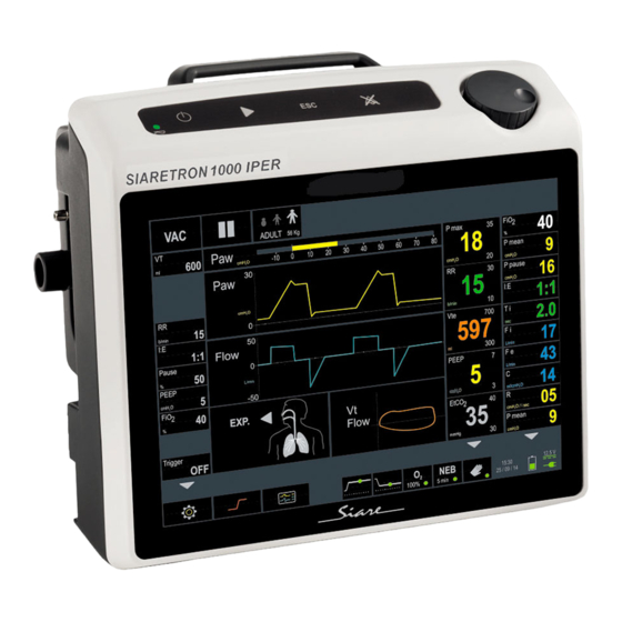
10.4’’ LED display touch screen On the front side of Aria 104 lung ventilator (hereinafter called lung ventilator) there is a 10.4” LED display (touch-screen) that visualizes all the information useful for patient ventilation. Operative mode selection, respiratory parameters setup and monitoring, visual and acoustic alarm warnings, loops and curves, are the main featured information visualized. -
Page 35: Selectable Operative Modes
2.3.1 Operative Modes Selectable • The Aria 104 includes the most modern ventilation modes: volume- controlled ventilation, pressure controlled ventilation, pressure supported, non invasive ventilation and manual ventilation. • The User can select one of these ventilation modes using the touch screen or/and the keyboard (please see cap. - Page 36 Volume targeted controlled ventilation synchronised with the patient if the inspiratory trigger is activated. The VC/VAC Operative Mode is not active when the PATIENT TYPE selected is: New Born. Volume targeted controlled ventilation synchronised with the patient if the inspiratory trigger for paediatric and neonatal patients is activated. The VC/VAC-BABY Operative Mode is not active when the PATIENT TYPE selected is: Adult.
-
Page 37: Operative Command: Start / Stop
2.3.2 Operative command: Start / Stop Two controls next to the operative mode’s selection is available and useful for the lung ventilator operations. The two controls are comparable with the ones located on the keyboard. Select the icon to Start ventilation in the selected operative mode. -
Page 38: Patient Data
2.3.3 Patient Data Alongside the Operative Command, the Patient Type set is specified (Adult, Child, New Born). In this way the default respiratory parameters are set automatically (breathing parameters and alarms levels). Select the icon for see PATIENT DATA parameters. PATIENT DATA displaying allows setting / modification of these data. -
Page 39: Alarm Visualization Area
2.3.4 Alarm visualization area • The lung ventilator features automatic means for detecting and identifying any conditions that might put the patient at risk (based on the level of urgency and seriousness), using acoustic or visual alarm signals. • The role of the alarm signal is to draw the attention of the User to the event as well as to inform him on the requested response speed. - Page 40 The User can display the alarm set limits, selecting the dedicated Alarms icon. After editing the alarm settings, the relative signal will remain active and the status icon will blink for a pre-set time. ALARM SILENCING • Select the bell icon (or press the RESET key) to interrupt the acoustic signal for a pre-set period of time.
-
Page 41: Physiological Respiratory Parameters (Prp)
2.3.5 Physiological Respiratory Parameters (PRP) • Select VC/VAC operative mode. • Selecting the PRP parameters icon. • The parameters related to the set Operative Mode are displayed. 2-20 User manual, DU3104101... -
Page 42: Prp List
Modification of a PRP parameter. Select a parameter (e.g. RR: Respiratory Rate) Select the RR icon. The bar for parameters setting is displayed. Decreases the parameter value Increases the parameter values Confirms the set value Cancels the setting bar 2.3.6 PRP list The parameters marked with BK are referred to the BACK-UP operative mode. - Page 43 Concentration percentage delivered to the patient can be set from 21% to 100%. Pressure Low (cmH O) - Pressure High (cmH Pressure levels to be set in APRV mode. Pause (%) Inspiratory pause time. The “inspiratory pause time” is displayed on the screen in % (% of the inspiratory time).
- Page 44 Sigh. Int. (b) Sigh. Activation frequency. Slope This value shows the inspiration flow speed. It is possible to set the slope of the acceleration curve of the turbine: the setting is from 1 to 4. The value of 4 corresponds to the maximum turbine acceleration (depending also by the mechanical inertia).
-
Page 45: Monitoring Of Respiratory Parameters
2.3.7 Monitoring of respiratory parameters • Based on the lung ventilator parameters set by the User and on the patient's characteristics, the lung ventilator is able to monitor and measure a series of values necessary for the patient's clinical evaluation. •... - Page 46 It shows the ratio between the inspiration time and the expiration time. It shows the oxygen concentration value (as percentage) inhaled by the patient. The inhaled oxygen concentration value is read by the system by means of the oxygen cell installed on the inspiratory line. It shows the current volume value during patient's expiratory phase: the unit of measurement is ml.
-
Page 47: Monitoring Of Additional Breathing Parameters
2.3.8 Monitoring of Additional breathing parameters • Based on the lung ventilator parameters set by the User and on the patient's characteristics, the lung ventilator is able to monitor and measure a series of values necessary for the patient's clinical evaluation. - Page 48 Expiratory peak flow Use the flow sensor installed on the expiratory line to measure the exhaled flow peak. At the beginning of the expiration, a flow peak arises in correspondence with the expiratory valve opening and it depends on the lung resistance and compliance This measure, just like the previous one, is not related to specific alarms thresholds, it only provides information on the ventilation status.
- Page 49 Inspiratory resistance It is the parameter of the lung mechanics that describes the resistance to the opposite flow of the airways: measured in O/(l/s). The greater the patient resistance, the higher the airway pressure you need to apply to obtain the same volume. The formula used by the ventilator to calculate the inspiratory resistance is as follows: Ri = (peak pressure –...
-
Page 50: Measures, Charts And Loops
2.3.9 Measures, charts and loops The lung ventilator is equipped with tools for charts and loops display so as to quickly and accurately notify the User on the patient's condition. The User selecting the icon (GRAPHIC’s set) can choose “which“and “how”... - Page 51 • To change the combination of curves displayed, the lung ventilator must be started. • Select “GRAPHICs” icon to quit the function. For more information, please see on cap. 4.10. 2-30 User manual, DU3104101...
-
Page 52: Loops Area: Lung Status
2.3.10 Loops area: lung status • The lung status icon simulates the patient's lungs, graphically displaying the respiratory cycle by alternatively switching the lungs color. • In fact, in case of patient's spontaneous activity (Trigger), the lung status icon turns to yellow and if the “Low Pressure” alarm value set has not been exceeded the icon turns red. -
Page 53: Operative Functions And General Informations
2.3.11 Operative functions and general informations In the lower side of GUI there are a series of controls and functions that are useful for the Aria 104 utilization. Leds: if Led is lit. indicate that the relevant function is enabled (or if it has been enabled);... - Page 54 NEBULIZER function The “NEB” function is active only when the lung ventilator is supplied by oxygen (connection: HIGH PRESSURE). MAN, operative mode (lit green led: MAN function has been enabled) About “MAN operative mode”, please see on cap. 4.7.12. • Date &...
-
Page 55: Menu, Alarms And Graphic's Set
2.3.12 Menu, Alarms and Graphics’ set In the lower side of GUI there are a series of functions that are fundamental for the Aria 104 utilization. Select the icon to access the SETTING MENU. Select the icon to “Turn OFF” the lung ventilator. - Page 56 When the lung ventilator is in Stand-by mode, selecting this icon it is possible to enter the PATIENT DATA setting (for more information, please see on cap. 4.3). The choice of the Patient Data (Adult, Child, New Born) set automatically the default physiologic respiratory parameters (PRP) of the lung ventilator (breathing parameters and alarms levels).
- Page 57 Product identification label The product identification label mentions the following information. Manufacturer Model name Main power supply Battery’s features Fuses features Regulation (CE mark) Serial number Symbols (see description) The mark identifies the protection level against electric shock (category of protection type B).
-
Page 58: Maintenance
MAINTENANCE To guarantee the regular ventilation operation of the Aria 104 lung ventilator for intensive care, emergency and transport (hereinafter called lung ventilator), perform the following maintenance interventions with the recommended frequency. All interventions must comply with to the practice and protocols in force in each facility. -
Page 59: Cleaning, Disinfection And Sterilization
Siare is aware that working procedures can differ considerably from one health care facility therefore it is impossible to indicate specific procedures suitable for every requirement. -
Page 60: General Indications
Rinse the parts well with clean hot water (tap water can be used) and leave to dry. Siare recommends that the components are checked every time they are cleaned and any damaged part should be replaced. Whenever a part or component is changed, check the functioning of the lung ventilator. -
Page 61: Disinfection By Immersion (Chemical)
Do not disinfect, sterilize or re-use disposable products. Disinfect and sterilize every time an infected patient is ventilated. In normal conditions, disinfect and sterilize depending on the frequency of the lung ventilator’s use and in any case at least once a month. ... -
Page 62: Cleaning, Disinfection And Sterilization Table
Cleaning, disinfection and sterilization table Component Procedure Notes Use a moistened disposable cloth with neutral detergent or a chemical substance or the like. Use water to remove any remaining traces of chemical. The User may use disinfectants (e.g. Buraton 10 F, diluted according to the manufacturer’s instructions or VPRO 60C°) to clean the components. - Page 63 WARNING !! Risk of injury for the patient It is necessary to have at least one spare patient circuit in stock for routine use and /or accidental breaks. Dismantle and clean: sterilize in an Before using again, eliminate autoclave, disinfect with steam or any humidity inside the Couplings and chemically.
- Page 64 Check the presence of Water trap If reusable: clean, then sterilize in fissures and replace in case of filter autoclave or chemically disinfect. damages. Other Carefully follow the manufacturer’s Refer to the accompanying accessories instructions. documentation. Perform daily checking’s of cable condition;...
-
Page 65: Sterilization Of Exp V. Monoblock (Exhalation Block With Flow Sensor)
6.3.1 Sterilization of EXP V. Monoblock (exhalation block with flow sensor) It is possible to sterilize the component with gamma rays or ethylene oxide (ETO). When disinfection is complete, EXP V. Disinfect with steam (93° - 10 minutes) or rinse with running, preferably Monoblock chemically. -
Page 66: Disposable Bacteria Filter
6.3.2 Disposable bacteria filter CAUTION It is important to use a disposable bacteria filter at the expiratory port of lung ventilator between the patient circuit’s expiratory limb and the expiratory flow sensor. Components that cannot be Disposable Do not clean or re-use if the filters are the destroyed should be sterilized bacteria filter disposable type. -
Page 67: Periodic Maintenance
When you require service, please indicate the serial number of the unit and the problem to SIARE or to your authorised technicians. SIARE assumes responsibility for all provisions foreseen by the law, if the equipment is used and maintained as per the instructions in this manual and the technical manual ... - Page 68 Frequency Component Procedure / Action Every day / when Oxygen sensor Calibrate according to the procedures described in necessary this manual. Condensation trap Check for any water collection, drain and clean filter when necessary. Lung ventilator General cleaning and checks. Turbine air filter Sterilize / disinfect according to the procedure EXP.
-
Page 69: Cleaning, Disinfection And Sterilization Before Use With Another Patient
All maintenance and/or repair operations require perfect knowledge of the lung ventilator and must therefore only be carried out by highly qualified personnel, specifically trained and formally authorised by SIARE. Inappropriate intervention or unauthorised modifications can compromise safety and cause danger to the patient. -
Page 70: Repairs And Spare Parts
Use only original SIARE spare parts or spare parts checked and approved by SIARE. 6.5.1 Spare parts kit for lung ventilator Code: R209000P1 Spare parts kit for annual maintenance to be used with the Aria 104, code 980104/A. Code: R209000CL Battery kit to be used with the Aria 104, code 980104/A. -
Page 71: Disposal
6.6.3 Disposal Batteries, accumulators, oxygen cells and electronic parts in general: do not put them in the fire, explosion risk do not open them, corrosion danger do not recharge batteries do not throw them away with normal waste. The batteries and the accumulators are special waste materials and they must be disposed of in appropriate containers in accordance with local regulations for the disposal of such waste materials. -
Page 72: Emc Tables - Guidance And Manufacturer's Declaration
A.6 EMC tables - Guidance and manufacturer’s declaration A.6.1 Table 1 Emissions Emissions test Conformity Electromagnetic environment – guidance The appliance uses RF energy only for its internal RF Emissions function. Therefore, its RF emissions are very low and Group 1 Cispr 11 are not likely to cause any interference in nearby electronic equipment. - Page 73 A.6.2 Table 2 Immunity aspects The device is intended for use in the electromagnetic environment specified below. The customer or the user of the device should assure that it is used in such an environment. Test level Electromagnetic environment - Immunity test Compliance level guidance...
- Page 74 A.6.3 Table 3 Immunity aspects at R.F. The device is intended for use in the electromagnetic environment specified below. The customer or the user of the device should assure that it is used in such an environment. Test level Compliance Electromagnetic environment - Immunity test level...
- Page 75 A.6.4 Table 4 Recommended separation distances between portable and mobile RF communications equipment and the device. The device is intended for use in an electromagnetic environment in which radiated RF disturbances are controlled. The customer or the user of the device can help prevent electromagnetic interference by maintaining a minimum distance between portable and mobile RF communications equipment (transmitters) and the device as recommended below, according to the maximum output power of the communications equipment.
- Page 76 Turbine-driven ventilation Touch Screen User’s Manual - 980104/A Version DU3104101 Revision - 01.02.2019 SIARE ENGINEERING INTERNATIONAL GROUP s.r.l. Via Giulio Pastore, 18 Località Crespellano, 40053 Valsamoggia (BO), ITALY Tel.: +39 051 969802 - Fax: +39 051 969809 E-mail: mail@siare.it Web: www.siare.it...
Need help?
Do you have a question about the Aria 104 and is the answer not in the manual?
Questions and answers