Table of Contents
Advertisement
Advertisement
Table of Contents

Subscribe to Our Youtube Channel
Related Manuals for Siare Siaretron 4000


Summary of Contents for Siare Siaretron 4000
- Page 1 Siaretron 4000 ICU Ventilator Turbine-driven ventilation Service Manual...
- Page 3 4000 ventilator and its use is limited to what is indicated in the guarantee supplied with the equipment. The contents of this manual do not in any way limit the right of SIARE ENGINEERING INTERNATIONAL GROUP s.r.l. to revise, change or modify without prior notice the equipment (including the relative software) described herein.
-
Page 4: Definitions
We would be grateful if you would send us your comments (see address at page IX). The SIARE trademark is used throughout this manual as an abbreviation for the manufacturer: SIARE ENGINEERING INTERNATIONAL GROUP s.r.l. -
Page 5: Warnings, Cautions And Notes
(model, serial number, ……) when requesting intervention. • SIARE recommends establishing a maintenance and service contract with SIARE or the local authorised service dealer in order to guarantee the scheduled maintenance required to operate the lung ventilator in a safe and correct manner. - Page 6 • The correct functioning of the lung ventilator can be impaired if original SIARE spare parts and accessories are not used; the use of other accessories is however allowed only if formally authorised by SIARE in accordance with current safety regulations.
- Page 7 • SIARE assumes all foreseen legal liability if the lung ventilator is used and periodically maintained according to the instructions contained in this manual: the Technical Assistance Report, drawn up and signed by the authorised SIARE technician, is proof of the completion of the scheduled maintenance.
- Page 8 The equipment cannot be used in the presence of explosive gases. WARNING !! Before connecting the lung ventilator to other electrical equipment not described in this manual, a request for authorisation should be sent to Siare. WARNING !! Qualified staff must make the regulation of ventilation parameters. WARNING !! An auxiliary ventilation system is suggested for the patients for which the ventilator represents a life support.
-
Page 9: Year Of Manufacture
SIARE declines all civil and penal responsibility in the following cases: • If the lung ventilator is used in conditions and for purposes not stated or described in this manual. • If the lung ventilator is used by non-qualified personnel. -
Page 10: Electromagnetic Compatibility
Electromagnetic Compatibility The Siaretron lung ventilator is designed to operate in the specified electromagnetic environment (see warning below). The customer or the user of Siaretron lung ventilator should ensure that it is used in such an electromagnetic environment. The Siaretron lung ventilator complies with the EN 60601-1-2 regulations on Electromagnetic Compatibility of electro-medical equipment. -
Page 11: Table Of Contents
3.5.4 EXP and INSP line rotary coupling ..................3-12 3.5.5 Air safety valve ........................3-14 3.6 Annual maintenance ......................3-15 3.6.1 Transducer O2 SIARE M20 .....................3-15 3.7 Final checks ........................3-17 3.8 Service procedures ......................3-19 3.8.1 Opening the ventilator crankcase ....................3-19 3.8.2 Replacing the batteries ......................3-20... - Page 12 TESTING PROCEDURES ......................5-1 5.1 Necessary equipment ......................5-2 5.2 Preliminary phase ......................... 5-2 5.2.1 Connections ..........................5-2 5.2.2 Pre-testing phase ........................5-3 5.2.3 Setting up the simulator standard parameters ................5-3 5.3 Test procedure ........................5-4 5.3.1 Aesthetics - Mechanical checks ....................5-4 5.3.2 Labels / markings presence .......................5-4 5.3.3 SW version ..........................5-4 5.3.4 SELF TEST ..........................5-4...
- Page 13 6.1 Introduction..........................6-2 6.1.1 Necessary equipment ........................6-3 6.2 Calibration programs ......................6-4 6.2.1 Turbine Characterization ......................6-5 6.2.2 Expiratory flow sensors calibration ....................6-8 6.2.3 VTEc............................6-12 6.2.4 Neb. ( ON – OFF ) ........................6-13 6.2.5 IRMA / ISA - Trend and Events ....................6-14 6.2.6 Exit ............................6-15 6.3 PEEP Calibration ........................
-
Page 14: Introduction
SIARE staff or qualified technical staff, formally authorised by SIARE, must know the full content, before carrying out the operations described below. The SIARE authorised technician avails of suitable tools and spare parts and is trained to work in compliance with product safety. - Page 15 Adult, paediatric and neonatal ventilation are available, thanks to an adjustable minimum Tidal Volume from 2 ml to 3000 ml. After the switching-on of the lung ventilator it is possible to choice the patient type (adult, paediatric and neonatal) setting the relevant default parameters.
-
Page 16: Main Features
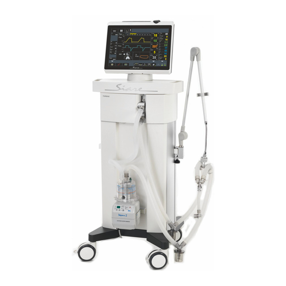
Siaretron 4000 ICU lung ventilator. Main features The Siaretron 4000 lung ventilator is composed of two main blocks: the trolley and the ventilator block. In turn, the lung ventilator block is divided in two parts: the upper part that includes a 12” TFT colour monitor, the board for the elaboration of all data and information (CPU) that supervises the operation and display of patient parameters. - Page 17 (see chapter 2). The Siaretron 4000 lung ventilator doesn’t require any high pressure air supply as it is equipped with an internal turbine. The lung ventilator incorporate a series of sensors for continuous patient monitoring, the most important of which are: •...
-
Page 18: Service
Service To ensure regular functioning of Siaretron 4000 intensive care lung ventilator (equipped with a turbine and with a 12” TFT display), adequately carry out all necessary interventions for the procedures and protocols in force in the individual structures. -
Page 19: Description
DESCRIPTION This chapter describes the Siaretron 4000 lung ventilator equipped with a turbine and with a 12” TFT display; the main parts and modules of whose it is composed are specially considered. Overall view WARNING!! All the pictures and the examples shown in the present chapter have the mere purpose of being an example and they do not make any reference to real clinical cases. - Page 20 The ventilator block can be used as a stand-alone part being detachable from the trolley, by positioning it on a flat surface.
- Page 21 Front view 12” LED monitor cfr. 2.4 Support for patient circuit supporting arm Support for humidifier Wheels diameter 10 cm (2 wheels with brakes) cfr. 2.4.1 Keyboard with soft key and encoder knob Transport handle cfr. 2.3 Attachments for patient circuit connection For the description of above listed parts make reference to the paragraphs beside highlighted.
-
Page 22: Lung Ventilator Front View
Lung ventilator front view Instruction label Refer to instruction manual/booklet O 2 SENSOR Oxygen cell O 2 SENSOR INLET Cable end RJ connector for O 2 cell connection EXP. VALVE Expiratory Valve EXP. FLOW RJ connector for flow sensor connection SENSOR INLET NEBULIZER Nebulizer circuit outlet (6 l/min) - Page 23 AIR SAFETY Safety air valve VALVE Specific inlet allowing inspiration of ambient air by the patient when the volume of fresh gas and/or gas for inspiration is insufficient. INSP. TO PATIENT Inspiration connector for patient circuit EXP. FROM Expiration connector for patient circuit PATIENT EXP.
-
Page 24: Electric Connections Side
2.3.1 Electric connections side Instruction label for connections General warning sign Instruction label: refer to instruction manual/booklet ON-OFF I / O switch for ventilator powering FUSE 2x1 AT Protection fuses for main power supply circuit at 220 Vac ( 2 x 1AT - 250V 100 - 240 VAC Plug for main power supply connection at 100 - 240 VAC (50 - 60 Hz / 50 W) - Page 25 Equipotential node This is used for connection to the equipotential node of the electrical system. EXT. ALARM Connection for external remote alarm Connector for external power supply at 12 Vdc - 7 A. 12 VDC IN (7 A) The external supply voltage can be through a battery or a continuous energy source with above mentioned features.
-
Page 26: Gas Supply Side
2.3.2 Gas supply side Instruction label for connections Instruction label: refer to instruction manual/booklet O 2 INLET Connector for O 2 hose connection from gas distribution system. LOW PRESSURE : the medical O 2 low pressure source should have a maximum flow of 15 l/min. HIGH PRESSURE : the medical O 2 high pressure source should be between 280 kPa and 600 kPa (2,8 - 6 bar / 40 - 86 psi). -
Page 27: 12'' Led Display
12’’ LED display On the upper side of the ventilator is a 12” LED display that will show all information necessary for patient ventilation. Operating mode selection, respiratory parameters setup and display, visual and acoustic alarm warnings are the main featured information visualized. By the use of the control keyboard and the encoder knob on the side of the ventilator to interact directly with the display: this system is defined as GUI (graphical user interface). -
Page 28: Keyboard With Soft Key And Encoder Knob
2.4.1 Keyboard with soft key and encoder knob ▪ ventilator A control keyboard and an encoder knob are available on the right side of the ▪ These components allow a rapid interaction between the User and the ventilator. Soft key to silence an active alarm ( ALARM RESET ). ESC soft key for rapid escape from MENÙ... - Page 29 The multifunction encoder knob is used to select, modify and confirm all the functions shown on display. The encoder knob is used to access the MENU function and then to function modes, parameters, alarms, parameters’ values and all is concerned to the normal operation of ventilator.
-
Page 30: Igu Setting
IGU setting For more details about : • Graphic setting and operative functions • MAIN MENU • Setting of breathing parameters - SET • Operative Mode • Graphs display • Ventilation monitoring : lungs icon • Monitoring of ventilatory parameters •... -
Page 31: Rear View
Rear view 12” LED monitor cfr. 2.4 Note! 15 poles connector to program CPU board by RENESAS programmer (see instruction on Service Manual, chapter 4) cfr. 3.3 Gas supply connection (O 2 ) Electric power supply block ON-OFF I / O switch for ventilator power supply FUSE Protection fuses for 220 Vac power supply circuit ( 2 x 3,15 AT - 250V without air compressor) -
Page 32: Product Identification Label
Product identification label The product identification label mentions the following information. • Manufacturer • Model name • Main power supply • Battery’s features • Fuses features • Regulation (CE mark) • Serial number • Symbols (see description) The mark identifies the protection level against electric shock (category of protection type B). -
Page 33: Procedures: Maintenance And Service
PROCEDURES: MAINTENANCE AND SERVICE This chapter describes the maintenance and service procedures for Siaretron 4000 lung ventilator equipped with a turbine and with a 12” TFT display in detail. This chapter describes the following operation. Introduction Maintenance procedures Daily maintenance... -
Page 34: Necessary Material
3.1.1 Necessary material WARNING! Personal injury hazard - physical This symbol appears where an operation is particularly important for product safety. For Siaretron 4000 service procedures you need the following equipment: • Electrical power supply cable • Medical gas •... -
Page 35: Maintenance Procedures
Maintenance procedures This paragraph describes the maintenance and service procedures for Siaretron 4000 lung ventilator in detail. The topics covered are the following: Maintenance procedures Daily maintenance Weekly maintenance Six-month maintenance ( 1000 hours ) 3.5.1 Necessary equipment 3.5.2 Oxygen Coupling 3.5.3 Exhalation valve block... -
Page 36: Daily Maintenance
Daily maintenance CAUTION Maintenance operations that should be carried out several times a day or according to the local procedures and reference standards. For more details see on chapter 7 Maintenance. • Gas supply “ OFF “ • Power supply “ OFF “ Cooling fan filter •... -
Page 37: Weekly Maintenance
CAUTION The O-Ring, code: M10003193, have to replaced 1 time to six month. • Remove the turbine air filters. • Replace with a new turbine air filters ( code, M53553009 ). • Reassemble the cover and filters on Siaretron 4000. -
Page 38: Six-Month Maintenance ( 1000 Hours )
Six-month maintenance ( 1000 hours ) Ref. Description Order Data Months Code Qty. OR 2056 M10002056 CONICAL SILENC. FILTER 1/8 P09900209 TURBINE AIR FILTER M53553009 OR 3193 M10003193 OR 2075 M10002075 OR 2015 M10002015 GREEN ONE-WAY VALVE A36.049030 OR 2087 M10002087 BLACK MEMBRANE D=15mm M55110009... - Page 39 Gas supply side SIARETRON Gas supply “ OFF “ • Remove the 90° oxygen couplings (20 mm hex key). CAUTION For more details about turbine air filters maintenance ( filters and O-Ring see on paragraph 3.4.
-
Page 40: Oxygen Coupling
Loosen the AIR coupling anticlockwise ( 6mm Allen wrench). • Replace O-Ring, code: M10002056. • Loosen the filter installed on Siaretron 4000 using a slotted screwdriver. • Replace the filter, code: P09900209. Pay utmost attention when mounting the filter, carefully screw it in. - Page 41 Front side Gas supply “ OFF “ Power supply “ OFF “ • Open the front doors of the trolley...
-
Page 42: Exhalation Valve Block
3.5.3 Exhalation valve block • Remove the cover of the valves unit. • Disconnect the RJ connector of the flow sensor power cable (EXP. FLOW SENSOR INLET) • Remove the unit from its seat: valve block and EXP. line rotary coupling •... - Page 43 • Replace O-Ring, code: M10002015. • Replace the membrane, code: A36.049030. The membrane must be placed correctly and the message SIDE UP should face upwards. • Open the block restoring the cover's position and tighten the 6 hex head screws (2.5mm Allen wrench).
-
Page 44: Exp And Insp Line Rotary Coupling
3.5.4 EXP and INSP line rotary coupling • INSP rotary coupling, removed from the inspiratory line. • Replace the 2 O-Ring placed inside the rotary coupling, code: M10002087. Replace the O-Ring on both rotary couplings. • Remove the one-way valve from the inspiratory line (use a nose plier). - Page 45 • Remount the one-way valve inside the inspiratory line. • Remount both rotary couplings on the INSP and EXP line.
-
Page 46: Air Safety Valve
3.5.5 Air safety valve • Remove the Air safety valve from the inspiratory block (use a nose plier or a slotted screwdriver). • Replace the green one-way rubber membrane, code P16000009. • Replace OR 128, code M10000128. • Remount the air safety valve inside the inspiratory block •... -
Page 47: Annual Maintenance
Description Order Data Months Code TRANSDUCER O2 SIARE M20 G95001000 SILICON PATIENT CIRCUIT 001562/SLR - /SLRP 3.6.1 Transducer O2 SIARE M20 • Disconnect the JACK of the oxygen sensor connection cable. • Unscrew it (anticlockwise) to remove the oxygen cell. - Page 48 • Replace the oxygen cell, code G95001000. • Turn the O 2 sensor clockwise to fasten it inside its seat paying attention not to damage its thread. • Insert the JACK of the connection cable in the suitable conector of the O 2 sensor WARNING! Patient injury hazard Make sure that the pin and the RJ connector are properly inserted in the dedicated socket inside the ventilator (O 2 SENSOR INLET)
-
Page 49: Final Checks
Final checks Follow the start-up procedures described in the User Manual. Follow the TEST and PRELIMINARY CHECKS procedures described in the User Manual. WARNING! Patient injury hazard After connecting the supply gas make sure that there are no losses. Make sure that the ventilator works properly. -
Page 50: Service Procedures
Service procedures WARNING! Patient injury hazard The procedures described are critical operations and must be carried out only by authorised staff as they might affect the equipment's safety and proper operation. WARNING! Clinician injury hazard Please turn off the ventilator and disconnect it from the mains and from the medical gas distribution line before carrying out any service procedure. -
Page 51: Replacing The Batteries
3.8.2 Replacing the batteries WARNING! Clinician injury hazard Make sure that the ventilator is disconnected from the mains. • Turn the screen at 45° • Unscrew the screws locking the fastening bracket of the two batteries • Remove the bracket; lift the battery from its seat; disconnect the connectors;... -
Page 52: Replacing The Turbine Module
3.8.3 Replacing the turbine module The turbine module represents the core of the ventilator pneumatic operation. WARNING! Breakage hazard The turbine module should not be open and in case of malfunction; please replace the entire module. • Disconnect the wirings connector •... - Page 53 • Push the turbine module inwards and remove it from the rear side of the ventilator • Pay utmost attention when removing the turbine module • Disconnect the pneumatic circuit tubes. 1. Yellow tube ( Di=2,5mm 2 ) 2. Transparent tube ( Di=4mm 2 ) 3.
- Page 54 WARNING! Patient / clinician injury hazard. Make sure that all parts are properly connected WARNING! Patient injury hazard After connecting the medical gas make sure that there are no losses NOTE 1. Yellow tube ( Di=2,5mm 2 ) – Nebulizer connection 2.
-
Page 55: Codes Of Supplied Accessories
Codes of supplied accessories G60005104 O 2 tube with 90° coupling (4mt) 600100 Nebulisation Set 001562/SLR Silicone Patient Circuit for Adults A36.049036 Antibacterial 22mm Filter G30105100 SHUKO-VDE supply cable G30104000 Supply cable ( 250V/10A L=2mt) G95001000 O2 cell... -
Page 56: Programming The Boards
Siaretron 4000. The specialist SIARE personnel or qualified technical personnel, formally authorised by SIARE, must be aware of the full contents of this manual before carrying out the operations described below. Authorised SIARE technicians have the appropriate tools and spare parts and are trained to operate while ensuring product and patient safety. -
Page 57: Siaretron 4000
Siaretron 4000 4.1.1 Equipment needed To program the boards mounted on Siaretron 4000 (in addition to a personal computer and the dedicated programming software), the following equipment is required: • Programmer: E8a RENESAS • USB cable to connect the PC and the programmer •... -
Page 58: Programming The Cpu Board (Cod. G3020204X)
4.1.2 Programming the CPU board (cod. G3020204x) Step Description Figure Siaretron 4000 OFF (not powered). Programmer + USB cable for connection to the PC – 4.1.2.1.1.1.1.1.1 Programmer + flat cable for connection to the CPU board programming connector. • Connect the USB plug to the PC port. - Page 59 Select the programming software icon on the PC desktop and launch the program. 4.1.2.1.1.1.1.1.3 Check: • Device: Flash memory code • Port: E8a 4.1.2.1.1.1.1.1.4 • Download File: checked • User/Data Area M30878FJ Device: Main CPU flash memory code User/Data Area: indicates the name of the programming file See paragraph 4.2 (How to change the MICRO - RENESAS device) M30878FJ if the Device: flash memory code...
- Page 60 Select the folder where the updated programming file is 4.1.2.1.1.1.1.1.5 .mot stored: GE245_Rev_xx • Select the updated file. 4.1.2.1.1.1.1.1.6 • Press Open: the file is ready to be downloaded.
- Page 61 User/Data Area: indicates the name of the updated programming file 4.1.2.1.1.1.1.1.7 The system is ready for programming. 4.1.2.1.1.1.1.1.8 Switch Siaretron 4000 ON. Both LEDs are lights on the programmer.
- Page 62 Press Program Flash. 4.1.2.1.1.1.1.1.9 Starts the programming procedure. Press OK 4.1.2.1.1.1.1.1.10 Do not select Power Supply, power is supplied to the memory by the CPU board.
- Page 63 Press OK 4.1.2.1.1.1.1.1.11 Defines the USB data transmission port. Starts the programming stage. 4.1.2.1.1.1.1.1.12 0% …… 100%.
- Page 64 • Press OK 4.1.2.1.1.1.1.1.13 Defines the software blocks to be erased before programming. • Erase complete. 4.1.2.1.1.1.1.1.14 • Programming in progress. 0% …… 100%.
- Page 65 • Program written successfully. • 4.1.2.1.1.1.1.1.15 Press Disconnect • Press OK 4.1.2.1.1.1.1.1.16 Defines system locking/unlocking - leave it checked: Do Nothing.
- Page 66 • Disconnect power to Siaretron 4000 4.1.2.1.1.1.1.1.18 • Disconnect the flat-cable programmer from the CPU board carefully The CPU board micro programming stage is complete. Disconnect the programmer carefully and correctly and switch off Siaretron 4000 to prevent future malfunctioning.
-
Page 67: How To Change The Micro - Renesas Device
How to change the MICRO - RENESAS device This operation is necessary when it is necessary to modify the Flash memory code to be programmed: M30878FJ Device: main CPU code R5F21238 Device: electrovalve board code By way of example only, the procedure below shows how to set the R5F21238 programming code for the electrovalves on the device. - Page 68 4.2.1.1.1.1.1.1.2 In Option select New Settings. Enter the device code (Flash memory) in question in Filter. 4.2.1.1.1.1.1.1.3 The program displays a list of Flash devices supported by the programmer.
- Page 69 Select the type of Flash memory entered. 4.2.1.1.1.1.1.1.4 > Next Check that the type of communication port (USB or serial) selected is correct: 4.2.1.1.1.1.1.1.5 > Next...
- Page 70 This specifies the type of connection. Leave the Default setting: Use Default. 4.2.1.1.1.1.1.1.6 > Next This specifies the type of programming options: it indicates the type and level of importance of the message that is displayed during the programming stage 4.2.1.1.1.1.1.1.7 •...
-
Page 71: Programming Summary
The display shows that the device has been modified and the system 4.2.1.1.1.1.1.1.8 is ready for programming. Select Program Flash. For programming procedures, proceed as outlined in previous chapters. The descriptions given are by way of example only and may vary depending on the software and hardware used. -
Page 72: Testing Procedures
The SIARE authorised technician avails of suitable tools and spare parts and is trained to work in compliance with product safety. This chapter provides an in-depth description of the Siaretron 4000 series equipment TESTING procedures. This chapter describes the following operation. -
Page 73: Necessary Equipment
• Patient circuit • A patient simulator fixed to the provided patient circuit terminal • Flow analyser For tests and checks, please use the patient simulator SIARE cod. LS.AB.001 that is equipped with variable resistance and compliance. Preliminary phase WARNING! All figures and examples featured in this chapter are purely informative and do not refer to real clinical cases. -
Page 74: Pre-Testing Phase
5.2.2 Pre-testing phase The clinician must follow the instructions in the User Manual. • Starting the ventilator and exceeding the “ SELF TEST “ phase • “ TEST ON DEMAND ” - Leak test • “ TEST ON DEMAND ” - O2 sensor calibration •... -
Page 75: Test Procedure
Test procedure For the tables summarising the test procedures please see 5.4. Before starting the test procedure, please make sure that the instructions in the previous chapters were properly followed. 5.3.1 Aesthetics - Mechanical checks Make sure that: the equipment is not deteriorated and has no damages (power cable, gas supply tubes, etc..). -
Page 76: Patient Circuit Loss (Test)
5.3.5 Patient circuit loss (TEST) Follow the indications in chapter 6 : Calibration 5.3.6 O2 Sensor calibration (TEST) Follow the indications in chapter 6 : Calibration • Patient circuit installed and plugged • Flow sensor and oxygen sensor installed At the end of the “ SELF TEST “ press the ESC key to go to TEST ON DEMAND - O2 sensor calibration. -
Page 77: Turbine Calibration
5.3.8 Turbine calibration Follow the indications in chapter 6 : Calibration • Siaretron 4000 OFF • Patient circuit installed and plugged • Flow sensor and oxygen sensor installed Press the soft keys on the ventilator keyboard at the same time : ALARM RESET and ON-OFF keys. -
Page 78: Respiratory Rates Check
Flow TRIGGER Select SET and configure the parameter Tr. I = 0.3 l/min • generate a vacuum in the patient simulator • check if the Tr. I activates and initiates a breath • make sure that the device does not activate the trigger automatically Set PEEP to 5 cmH •... -
Page 79: Low Pressure Circuit Loss
5.3.12 Low pressure circuit loss Select SET and configure the values below: • Pause = 50% • = 21% - 100% Make sure that the pressure generated (with FiO = 21% and 100%) during the breath, remains displayed on the pressure gauge of the patient simulator and on the PAW, for the entire time set for Pause. -
Page 80: Neb. Function
5.3.17 NEB. Function Operating Mode : VC/VAC Make sure that when the SET - NEB is selected, the ventilator generates an flow of 6 l/min at the nebulizer output for the duration of the inspiratory time. Green Led on. Make sure that the monitored parameters are consistent with the set parameters. 5.3.18 100% O2 function Operating Mode : VC/VAC Make sure that when the SET - O2 100% function is selected, the device keeps... -
Page 81: Apcv (Assisted Pressure Control Ventilation) Operating Mode
High / Low Note! Operations to be carried out during FiO (%) check FiO 2 Alarm Use the encoder knob and select - MENU - SETUP - ALARMS. Set the values for Low alarm (e.g. 30% ) and High alarm (e.g. FiO 2 FiO 2 70% ) so as to activate the visual and acoustic signals during O... -
Page 82: Vc/Vac Operating Mode
5.3.21 VC/VAC operating mode Volume Press the START key and make sure that the device operates as intended (according to the relative operating mode). Monitored parameters check. Set the following Current Volume (Vti) values and the corresponding Respiratory Rate values (RR), as shown in the table. Make sure that the Current Volume values displayed on the flow analyser ( Vti ) and on the ventilator monitored parameters ( Vte ) fall within the corresponding acceptance limits (+/- 10%). -
Page 83: Vc/Vac Baby Operating Mode
5.3.22 VC/VAC BABY operating mode Press the START key and make sure that the device operates as intended (according to the relative operating mode). Set the following Current Volume (Vte) values and the corresponding Respiratory Rate values (RR), as shown in the table. Vte (ml) RR (bpm) Lower acceptance... -
Page 84: I:e Ratio Check
5.3.24 I:E ratio check Operating Mode : VC/VAC Change the I:E ratios on the ventilator and check the correspondence on the analyser. Go to additional ventilator monitored parameters and check if the T. INSP and T. EXP. values are aligned with I:E. 5.3.25 SIGH function Operating Mode : VC/VAC •... -
Page 85: Apcv-Tv (Volume Targeted Assisted Pressure Control Ventilation)
Low/high Note! Operations to be carried out during PEEP check PEEP alarm Use the encoder knob and select - MENU - SETUP - ALARMS. Set the values for Low PEEP alarm (e.g. 7 cmH 2 O ) and High PEEP alarm(e.g. -
Page 86: Psv (Pressure Support Ventilation)
5.3.28 PSV (Pressure Support Ventilation) Press the START key and make sure that the device operates as intended (according to the relative operating mode). Monitored parameters check. Based on the time set in parameter MENU – SETUP – APNOEA TIME (sec), Apnoea Back check the proper mode activation. -
Page 87: Man Function
5.3.30 MAN Function Operating Mode : PSV-TV Make sure that when the SET - MAN function is selected, the device activates a breath with the same features as the selected operating mode. Green Led on. 5.3.31 V-SIMV (Volume-Synchronised Intermittent Mandatory Ventilation) Set the following parameters: •... -
Page 88: P-Simv (Pressure-Synchronised Intermittent Mandatory Ventilation)
5.3.32 P-SIMV (Pressure-Synchronised Intermittent Mandatory Ventilation) Set the following parameters: • Tr. I : 0.3 L/min • Tr.E : 25% • PS : 20 cmH 2 O • RRsimv : 6 bpm • PINSP : 15 cmH 2 O • PEEP : OFF Press the START key and make sure that the ventilator generates MANDATORY breaths based on the set parameters (PINSP set). -
Page 89: Cpap (Continuous Positive Airway Pressure) Operating Mode
5.3.33 CPAP (Continuous Positive Airway Pressure) operating mode Press the START key and make sure that the device operates as intended (according to the relative operating mode). Monitored parameters check. Generate a vacuum in the patient circuit (using the patient simulator) and make sure that: •... -
Page 90: Gas Sensor
5.3.36 Gas Sensor EtCO2 Alarm Use the encoder knob and select - MENU - SETUP - ALARMS. Set the values for Low EtCO2 alarm (e.g. 1.0% ) and High EtCO2 alarm (e.g. 5.0% ) so as to activate the visual and acoustic signals during CO 2 concentrations check phase 5.3.37 Measured respiratory parameters Check the correspondence between the set respiratory values and the time,... -
Page 91: Set Language
5.3.41 Set Language Use the encoder knob and select - MENU - SETUP - LANGUAGE: set the language being used. 5.3.42 Electrical test sheet presence Safety conductor resistance and dispersion currents check • Connect the ventilator supply cable to the SAFETY-TESTER. •... -
Page 92: Test Table
Test table Ref. Check Measured values Result Notes Pos. Neg. Aesthetics Pos. Neg. Presence of markings Pos. Neg. Software version Rel. ________ Pos. Neg. SELF TEST Pos. Neg. Turbine Pos. ... - Page 93 Siaretron Set 21 ________ ________ Set 30 ________ ________ FiO2 Pos. Neg. Set 60 ________ ________ Set 80 ________ ________ Set 100 ________ ________ Pos. Neg. Low/high FiO 2 alarm Operating mode APCV Pos. Neg. 10 cmH 2 O Meas.
- Page 94 Siaretron Pos. Neg. ________ ________ PEEP ________ ________ ________ ________ ________ ________ ________ ________ Pos. Neg. Low/high PEEP alarm Pos. Neg. APCV-TV operating mode Pos. Neg. PSV operating mode Pos. Neg. Apnoea Back Up ...
-
Page 95: Calibration Procedures
CALIBRATION PROCEDURES This chapter describes the calibration procedures for Siaretron 4000 intensive care lung ventilator in detail. This chapter describes the following operation. 6.1 Introduction 6.1.1 Necessary equipment 6.2 Calibration programs 6.2.1 Turbine Characterization 6.2.2 Expiratory flow sensors calibration 6.2.3 VTEc 6.2.4 Neb. -
Page 96: Introduction
Service Manual. ▪ The specialist SIARE staff or qualified technical staff, formally authorised by SIARE, must know the full content of this manual, before carrying out the operations described below. ▪ The SIARE authorised technician avails of suitable tools and spare parts and is trained to work in compliance with product safety. -
Page 97: Necessary Equipment
6.1.1 Necessary equipment CAUTION. Personal injury hazard - physical This symbol appears where an operation is particularly important for product safety. For Siaretron 4000 service procedures you need the following equipment: • Electrical power supply cable • Medical gas •... -
Page 98: Calibration Programs
20% between the set value and the value read for exhaled (Vte) Current Volume (tidal). Step Description Figure Required device configuration: • Siaretron 4000 OFF • gas supply ON • power supply ON • patient circuit connected to INSP. and ESP. couplings with plugged... -
Page 99: Turbine Characterization
WARNING! Patient injury hazard • There are various procedures for device calibration. • Use the Encoder knob to select (turn) and activate (press) the desired procedure. • If there is no CALIBRATION PROGRAMS confirm, the system automatically switches to SELF TEST phase. 6.2.1 Turbine Characterization Turn the knob and select the function: Turbine Characterization... - Page 100 The following information are displayed on ventilator. • Siaretron 4000 – 12-SHA-TA-S-G (HW 1.1 - SW 1.6.x): lung ventilator type, main board ver. HW and SW • Total operating hours Total and partial operating hours (partial ones can be •...
- Page 101 • Turbine speed During the turbine characterization, the characteristic of the turbine is restored associating the pressure measured by the pressure sensor (from 0 to 80 cmH 2 O approx) to the PWM control of the turbine and this last to the turbine number of laps.
-
Page 102: Expiratory Flow Sensors Calibration
6.2.2 Expiratory flow sensors calibration Turn the knob and select the function: Expiratory flow sensors calibration. Siaretron displays the activation screen for flow sensor calibration: • Press START to begin the calibration. • Press ESC to verify the calibration. The activation of the Respiratory Flow Sensors Calibration program is necessary in the following cases: •... - Page 103 The following information are displayed on the screen • Siaretron 4000 – 12-SHA-TA-S-G (HW 1.1 - SW 1.6.x): lung ventilator type, main board ver. HW and SW • Turbine current: current supplied to the turbine • Turbine PWN (%): PWM turbine percentage (%) •...
- Page 104 Calibration Phase (0 …….. 12) : there are 12 calibration phases, corresponding to 12 flow values provided by SIARETRON. During the procedure, the flow generated by the turbine (from 0 to 100 l/min) is measured by the internal inspiration flow sensor and the systen restores the characteristic of the expired flow sensor associating to the ADC value of the outlest pressure the one of the correspondent flow measured by the internal inspiration sensor (ref.sensor).
- Page 105 At the end of the CALIBRATION, SIARETRON automatically switches to SELF TEST phase. At the end of the “ SELF TEST “ phase, there are two options available. • Touch the ESC key to access TEST ON DEMAND • Press the START key to access the STAND-BY page SELF TEST phase : please consult the User’s Manual...
-
Page 106: Vtec
6.2.3 VTEc The VTEc option, once enabled, (VTEc ON) allows to optimize the measure of the volume deriving from an operation of integration of the Fe flow measured by the expired flow sensor. • Turn the encoder knob to select the parameter to be calibrated: the activated message is highlighted. -
Page 107: Neb. ( On - Off )
6.2.4 Neb. ( ON – OFF ) Turn and press the encoder knob to enable (disable) the Neb function ( Nebulizer ON- Nebulizer OFF) • Select Exit to go to the “ SELF TEST “ phase and escape from “ CALIBRATION PROGRAMS “... -
Page 108: Irma / Isa - Trend And Events
6.2.5 IRMA / ISA - Trend and Events From software version sw 1.6.6 it is available a string for: • IRMA / ISA EtCO 2 Sensor • Trends and Events Both functions are not active during the using in hyperbaric chamber. In order to be able to use these functions it is necessary an interface cable for the connection of the RS 232 port to the IRMA/ISA sensors or for the connections to a PC serial port to download the data. -
Page 109: Exit
6.2.6 Exit Turn the knob and select the option: Exit. SIARETRON switches to SELF TEST phase. At the end of the “ SELF TEST “ phase, there are two options available. • Touch the ESC key to access TEST ON DEMAND. •... -
Page 110: Peep Calibration
• Lung ventilator ready for use: medical gas and power supply ON. • Connect the patient circuit to a simulator. • Turn Siaretron 4000 ON (please see the user manual). • Set a PEEP value equal to 0 cmH 2 O and make sure that the operating mode is VC/VAC. - Page 111 Set a PEEP value equal to 10 cmH 2 O and make sure that in VAC Always check only the first act. operating mode, the system detects a value equal to the one set. If the monitored values go back to the conditions specified at the beginning (that should be changed), please use the PEEP regulator.
-
Page 112: Zeroing Of "Partial Operating Hours
Zeroing of “partial operating hours” To zero the partial operating hours of the ventilator, it’s necessary to enter the Turbine characterization screen (see on cfr. 6.2.1 Turbine characterization). • Press in sequence the key: ALARM RESET - STAND-BY/ON-OFF • Repeat the sequence twice. ALARM RESET - STAND-BY/ON-OFF... - Page 113 • Make sure that the partial operating hours have been effectively zeroed • Total operating hours : 00007 • Partial operating hours : 00000 • Exit from Turbine characterization screen pressing first START and immediately after press ESC. • The ventilator immediately switches to the CALIBRATION PROGRAMS screen. •...
-
Page 114: Calibrations On Board
Calibrations on board The CPU / G3020204x board features several regulation trimmers. The trimmers were pre-calibrated at factory premises. 6.5.1 CPU / G3020204x Board Trimmer calibration GAIN pressure MPX2010 Trimmer calibration OFFSET = 0 pressure MPX2010 Trimmer calibration OFFSET = 0 sensor O 2 Trimmer calibration GAIN sensor O 2 10.00Vdc ±... -
Page 115: Additional Tests And Checks
CAUTION. Personal injury hazard - physical After carrying out the maintenance and service operations necessary for the device, proceed with a series of checks before using Siaretron 4000 on a patient. The lung ventilator must be ON, in STAND-BY mode, and the checks below should be carried out. -
Page 116: Conclusions
Change the alarms setup based on the clinical situation. WARNING! Operator and patient injury hazard The intensive care lung ventilator Siaretron 4000 must be inspected and serviced once it reaches 1000 hours of operation or, in case of limited use, at least once every 6 months. -
Page 117: Maintenance
MAINTENANCE To guarantee the regular ventilator operation of the Siaretron 4000 lung ventilator for intensive care (hereinafter called ventilator), perform the following maintenance interventions with the recommended frequency. All interventions must be conform to the practice and protocols in force in each facility. - Page 118 All maintenance and/or repair operations require perfect knowledge of the ventilator and must therefore only be carried out by highly qualified personnel, specifically trained and formally authorised by SIARE. Inappropriate intervention or unauthorised modifications can compromise safety and cause danger to the patient.
- Page 119 ▪ Siare is aware that working procedures can differ considerably from one health structure to another: it is therefore impossible to indicate specific procedures that are suitable for all requirements.
-
Page 120: General Indications
• Rinse the parts well with clean hot water (tap water can be used) and leave to dry. • Siare recommends that the components should be checked every time they are cleaned and any damaged parts should be replaced. •... -
Page 121: Disinfection By Immersion (Chemical)
• Do not disinfect, sterilize or re-use disposable products. • Disinfect and sterilize every time an infected patient is ventilated. • In normal conditions, disinfect and sterilize according to how often the ventilator is used and in any case at least once a month. •... -
Page 122: Cleaning, Disinfection And Sterilization Table
7.3.4 Cleaning, disinfection and sterilization table Component Procedure Notes Outer casing Use a moistened disposable cloth with Make sure that no sprays neutral detergent or a chemical substance or liquids penetrate inside or the like. Use water to remove any the equipment and the remaining traces of chemical. - Page 123 The patient circuit can be sterilized by means of steam but this can lead to early wear of the tubes. Yellowing and reduced flexibility are side effects caused by sterilization using steam. Turbine air Dismantle and clean with hot water and a Before mounting the filter filters neutral detergent solution.
- Page 124 following the instructions of the instructions responsible doctors or recommended by the Manufacturer. Hang up the clean mask to provide that it is completely dry before use. Always clean the mask and the hoses or use a new mask in case the lung ventilator must be used with a different patient.
-
Page 125: Periodic Maintenance
When you require service, please indicate the serial number of the unit and the problem to SIARE or to your authorised technicians. • SIARE assumes responsibility for all provisions foreseen by the law, if the equipment is used and maintained as per the instructions in this manual and the technical manual •... - Page 126 Frequency Component Procedure / Action Condensation trap Check for any water collection, drain and clean filter when necessary. Lung ventilator General cleaning and checks. Turbine air filters Sterilize / disinfect according to the procedure EXP. V. Monoblock described in this manual and according to local standards.
-
Page 127: Cleaning, Disinfection And Sterilization Before Use With Another Patient
All maintenance and/or repair operations require perfect knowledge of the ventilator and must therefore only be carried out by highly qualified personnel, specifically trained and formally authorised by SIARE. Inappropriate intervention or unauthorised modifications can compromise safety and cause danger to the patient. -
Page 128: Repairs And Spare Parts
3/6 months, depending on the storage temperature. See the technical sheet in the Appendix A. Repackaging and shipment If it is necessary to return the equipment to SIARE for any reason, we suggest using the original packaging to prevent damage to the equipment during shipment. -
Page 129: Disposal
Disposal Batteries, accumulators, oxygen cells and electronic parts in general: • do not put them in the fire, explosion risk • do not open them, corrosion danger • do not recharge batteries • do not throw them away with normal waste. The batteries and the accumulators are special waste materials and they must be disposed of in appropriate containers in accordance with local regulations for the disposal of such waste materials. -
Page 130: Diagrams
DIAGRAMS This chapter collects all the information and data for complete know-how and interpretation of the Service Manual for Siaretron 4000 intensive care lung ventilators. This chapter describes the following operation. Boards blocks diagram 8.1.1 Ventilator connections and supplies diagram Electronic boards 8.2.1 Description... - Page 131 Boards blocks diagram...
- Page 132 8.1.1 Ventilator connections and supplies diagram...
-
Page 133: Electronic Boards
Electronic boards 8.2.1 Description You can see below the boards layout along with a short description of their role and logic of operation. • Main Board - CPU / G30202041 • Inverter Board - G30221000 • Turbine Unit Board - G80412000 •... -
Page 134: Board Cpu / G30202041
8.2.3 Board CPU / G30202041 CPU Programming Not used Inhaled flow sensor Not used LCD monitor Not used Exhaled flow sensor Not used Oxygen Cell Valves unit board supply confirmation Not used (5.7” Inverter monitor ) CN10 CN11 RS232 / LAN connections board CN13 Encoder Board CAN connection... - Page 135 Trimmer calibration GAIN pressure MPX2010 Trimmer calibration OFFSET = 0 pressure MPX2010 Trimmer calibration OFFSET = 0 sensor O 2 Trimmer calibration GAIN sensor O 2 10.00Vdc ± 0.01Vdc supply voltage calibration trimmer...
-
Page 136: Pneumatic Diagrams
Pneumatic diagram... -
Page 137: Pneumatic Diagram Description
8.3.1 Pneumatic diagram description The mechanical study and diagram of the pneumatic system for gas delivery and dosage is given in the attached illustrations. The system is designed to safely administer the correct amount of respiratory gas to the patient, and is completely controlled by the electronic system. The device can be configured to use either a single or dual limb patient circuit (see the two pneumatic diagrams attached). - Page 138 EV1-NA 12 V pilot electro-valve, normally open, controlled by microprocessor, it is closed when the PEEP value is set on 0 or in case the high pressure alarm limit is reached. EV2-NA 12 V pilot electro-valve, normally open, controlled by microprocessor, it has the function to regulate the necessary flow to drive the expiratory valve.
- Page 139 ANNEX This chapter collects all the information and data for complete know-how and interpretation of the Service Manual for Siaretron 4000 lung ventilator equipped with a turbine and with a 12” TFT display This chapter describes the following operation. Equipment 9.1.1 Measuring instruments...
- Page 140 Equipment This paragraph illustrates what specific equipment is necessary to correctly and safely carry out the maintenance and service procedures planned for Siaretron 4000 lung ventilator. 9.1.1 Measuring instruments • Electrical safety analyser • Digital multimeter • Electronic test for lung ventilators to measure: Pressure, Flow, Volume, Respiratory rate, Concentration of O 2 •...
-
Page 141: Technical Data Sheet
Technical data sheet Siaretron 4000 code 960402 TECHNICAL DATA SHEET See User Manual. -
Page 142: Medical Gas Identification Colours
Medical gas identification colours SYMBOL ISO & UK GERMANY OXYGEN White Green Blue NITROUS OXIDE Blue Blue Grey CARBON DIOXIDE Grey Grey CYCLOPROPANE Orange Orange MEDICAL AIR White and Yellow Yellow Black ENTONOX 50/50 N O + O Blue and White VACUUM Yellow... -
Page 143: Glossary
Glossary Ampere (unit of measurement for current intensity) Clinical alarm An alarm that can indicate an anomalous physiological condition. High priority alarm As defined by the international standards organisations, it is an alarm that requires immediate intervention to ensure the patient’s health. During a high priority alarm, the corresponding red signal flashes rapidly and an acoustic signal for high priority is emitted (a series of five tones repeated twice, followed by a pause, then repeated again) - Page 144 DISS Diameter Index Safety Standard: a standard for high pressure gas input connectors. Electro-magnetic compatibility. European standard that refers to the European Common Market. Error Category of conditions detected during system functioning that leads to open safety status. A ventilator that has a FAULT cannot be clinically used and requires immediate maintenance.
- Page 145 Alarm message A message that appears together with alarm signalling; it consists of a basic message that identifies the alarm type. Minute (unit of time). Millilitre (unit of volume). mode Ventilation mode, algorithm that determines the ventilation type and sequence: the system offers a series of possible choices, including the possibility to choose between assisted, controlled, spontaneous or synchronised ventilation.
- Page 146 TREND Monitoring over medium to long period of respiratory parameters. Pressure trigger Method of recognising a patient's inspiratory force, where the ventilator controls the pressure in the patient's circuit. The ventilator activates ventilation when the pressure in the airways decreases by a quantity at least equal to the threshold value selected in a set time.
-
Page 147: Test Procedure Table
Test procedure table Ref. Check Measured values Result Notes Pos. Neg. Aesthetics Pos. Neg. Presence of markings Pos. Neg. Software version Rel. ________ Pos. Neg. SELF TEST Pos. Neg. Turbine ... - Page 148 Siaretron Set 21 ________ ________ Set 30 ________ ________ FiO2 Pos. Neg. Set 60 ________ ________ Set 80 ________ ________ Set 100 ________ ________ Pos. Neg. Low/high FiO 2 alarm Operating mode APCV Pos. Neg. 10 cmH 2 O Meas.
- Page 149 Siaretron Pos. Neg. ________ ________ PEEP ________ ________ ________ ________ ________ ________ ________ ________ Pos. Neg. Low/high PEEP alarm Pos. Neg. APCV-TV operating mode Pos. Neg. PSV operating mode Pos. Neg. Apnoea Back Up ...
- Page 150 Siaretron 4000 ICU Ventilator Turbine-driven ventilation Service Manual SIARE ENGINEERING INTERNATIONAL GROUP s.r.l. Via Giulio Pastore, 18 Località Crespellano, 40053 Valsamoggia (BO), ITALY Tel.: +39 051 969802 - Fax: +39 051 969366 E-mail: mail@siare.it Web: www.siare.it...
Need help?
Do you have a question about the Siaretron 4000 and is the answer not in the manual?
Questions and answers