Lightware UMX-HDMI-140 Series User Manual
Universal multimedia switcher
Hide thumbs
Also See for UMX-HDMI-140 Series:
- User manual (161 pages) ,
- Quick start manual (2 pages) ,
- User manual (93 pages)

Related Manuals for Lightware UMX-HDMI-140 Series


Summary of Contents for Lightware UMX-HDMI-140 Series
- Page 1 User’s Manual UMX-HDMI-140 UMX-HDMI-140-Plus Universal Multimedia Switcher v3.0 27-10-2020 ...
- Page 2 UMX-HDMI-140 series– User's Manual Important Safety Instructions Waste Electrical & Electronic Equipment Common Safety Symbols WEEE Class II apparatus construction. Symbol Description This marking shown on the product or its literature, The equipment should be operated only from the power source indicates that it should not be disposed with other indicated on the product.
- Page 3 #dhcp This keyword is placed at the DHCP (dynamic IP address) setting in the front panel operation, the Lightware Device Controller (LDC) and the LW3 programmer's reference section. See the list of all hashtag keywords of the document in the...
-
Page 4: Table Of Contents
5.12. Backup (Configuration Cloning) ..........56 2.4.3. Enable DHCP IP Address ............... 16 5.12.1. Steps in a Nutshell ............... 56 5. SOFTWARE CONTROL - LIGHTWARE DEVICE CONTROLLER ..31 2.4.4. Reset to Factory Default Settings ..........16 5.12.2. Save the Settings of a Device (Backup) ........56 5.1. Install and Upgrade ..............32... - Page 5 UMX-HDMI-140 series– User's Manual Table of Contents 6.4.6. View Connection State on the Output ........... 63 7.4.6. Restore the Factory Default Settings ..........76 7.6.13. Mute Audio Output ............... 86 6.4.7. View Crosspoint Size ..............64 7.4.7. Lock the Front Panel Buttons ............77 7.6.14. Unmute Audio Output ..............
- Page 6 UMX-HDMI-140 series– User's Manual Table of Contents 7.12.5. Sending a TCP Text (ASCII-format) via TCP Port ....... 94 10.2. HDCP Management ..............113 7.12.6. Sending a UDP Binary Message (HEX-format) via TCP Port ..94 10.2.1. Protected and Unprotected Content ......... 113 7.12.7. Sending a Message (ASCII-format) via Serial Port ....
-
Page 7: Introduction
1. Introduction UMX-HDMI-140 series– User's Manual I ntroduction Thank you for choosing Lightware’s UMX-HDMI-140 series switcher family. In the first chapter we would like to introduce the device highlighting the most important features in the below listed sections: Description Î... -
Page 8: Description
UMX-HDMI-140 UMX-HDMI-140-Plus Video Ports About the Serial Number VGA input Lightware devices contain a label indicating the unique serial number of the product. The structure is the HDMI input following: DisplayPort input ... -
Page 9: Features
1. Introduction UMX-HDMI-140 series– User's Manual 1.4. Features Advanced Control Features (Only for UMX-HDMI-140-Plus) Consumer Electronic Control 3D and 4K Support High bandwidth allows extension of resolutions up to 4K and even 3D sources and displays are Supports transmitting standard CEC commands in order to remote control the source or sink supported. -
Page 10: Typical Applications
Electrical Connections section. UMX-HDMI-140 transmits HDMI audio/video signal toward the sink devices. The Lightware HDMI-4K De-embedder de-embeds the audio signal and transmits it to the Active speakers. The De-embedder does not need local powering because it can be supplied via the HDMI cable by the source and the cable extensions... - Page 11 VC. The Switcher can be controlled easily via LAN network using our controller software (LDC); see the details in the Software Control - Lightware Device Controller chapter. The HDMI cable between the Switcher and the codec can be up to 20 meters thanks to the built-in...
- Page 12 The Collaboration Room is built with a ceiling mounted projector and a projection screen. The output of UMX-HDMI-140 is connected to the projector by HDMI cable which can be extended up to 40 meters using a Lightware HDMI-Extender device. The HDMI-Extender does not need local powering because it can be supplied via the HDMI cable.
-
Page 13: Product Overview
2. Product Overview UMX-HDMI-140 series– User's Manual P roduct Overview The following sections are about the physical structure of the device, input/ output ports and connectors: Front View Î Rear View Î Front Panel Operation - AV Functions Î... -
Page 14: Front View
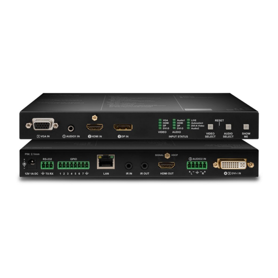
2. Product Overview UMX-HDMI-140 series– User's Manual 2.1. Front View Status LEDs Input Status LEDs OFF: Input is not selected. BLINKING: Input is selected, and signal is not detected. Input is selected and signal is present. VGA input D-SUB connector for analog video signal. -
Page 15: Rear View
Ethernet Locking RJ-45 connector for configuring the device using Lightware Device Controller (LDC), or upgrading it using Lightware Device Updater (LDU). Any third-party control system can use this port to control the device. IR IN and OUT 3-pole TRS connector, also known as 3.5 mm (1/8”) jack plug for optional IR receiver (IR IN) and transmitter (IR OUT) connection. -
Page 16: Front Panel Operation - Av Functions
2.4.2. Customize Button Function HDMI DVI-D The audio and input select function can be disabled by Lightware Device Controller (LDC) software or LW3 AUTOSELECT DVI-A protocol command and the buttons can configured for any function in the Event Manager. You can find more details about Autoselect feature in the The Autoselect Feature section. -
Page 17: Control Lock
2. Product Overview UMX-HDMI-140 series– User's Manual 2.4.5. Control Lock Press the Audio Select and Show Me buttons together (within 100 ms) to disable/enable front panel buttons; front panel LEDs blink 3 times when locking/unlocking. If the control lock is enabled and a button is pressed, front panel LEDs blink 3 times. -
Page 18: Installation
3. Installation UMX-HDMI-140 series– User's Manual I nstallation The chapter is about the installation of the device and connecting to other appliances, presenting also the mounting options and further assembly steps: Mounting Options Î Electrical Connections Î... -
Page 19: Mounting Options
The UD-kit double makes it easy to mount a single switcher on any flat surface (e.g. furniture). To mount the switcher Lightware supplies optional accessories for different usage. There are two kinds of mounting kits with similar fixing method. The switcher has two mounting holes with inner thread on the bottom side;... -
Page 20: Vga Connector
3. Installation UMX-HDMI-140 series– User's Manual 3.2.2. VGA Connector 3.2.4. HDMI Connector The switcher provides a standard 15-pole D-SUB female connector for connecting The extender provides standard 19 pole HDMI connector for output. Always use high quality VGA devices. Always use high-quality VGA cable for connecting sources and displays;... -
Page 21: Ethernet Connector (Lan Port)
The pin assignments are the following for the detector and the emitter: Wiring of TPS and LAN Cables Lightware recommends the termination of LAN cables on the basis of TIA/EIA T 568 A or TIA/EIA T 568 B standards. -
Page 22: Connecting Steps
3. Installation UMX-HDMI-140 series– User's Manual 3.3. Connecting Steps Connect the switcher and the sources using the inputs and VGA / DVI-I / HDMI / DisplayPort cables. HDMI Audio Optionally connect an audio device (e.g. the VGA laptop) to the audio input port. -
Page 23: Device Concept
4. Device Concept UMX-HDMI-140 series– User's Manual D evice Concept The following chapter describes the features of the device with few real-life examples. The topics that are described Universal Switcher Concept Î Port Diagram Î Audio Interface Î... -
Page 24: Universal Switcher Concept
UMX-HDMI-140 is a universal audio/video switcher with analog/digital conversion and audio embedding The following figure describes the port diagram of the UMX-HDMI-140 series switcher: functions. The device receives analog (VGA, DVI-A) and digital (DP, HDMI, DVI-D) video signals and transmits HDMI. -
Page 25: Audio Interface
4. Device Concept UMX-HDMI-140 series– User's Manual 4.3. Audio Interface 4.3.2. Audio Options - Example 4.3.1. Audio Input Modes The device can receive embedded digital audio signal on the HDMI, DisplayPort, and DVI-D input ports and analog audio signal on the Jack and the Phoenix input ports. -
Page 26: Video Interface
Laptop VGA IN Port with Port with priority priority 1 has a 1 is selected Priorities can be set in Lightware Device Controller software, see related settings in the Video Output section. valid signal? Port with Port with priority priority 2 has a... -
Page 27: Control Features
4. Device Concept UMX-HDMI-140 series– User's Manual 4.5. Control Features Event Manager Mode Third-party devices can be controlled from Event Manager in this mode. ASCII characters and binary data in 4.5.1. Serial Interface hexadecimal format can be used in this case. -
Page 28: Recognizer
This feature is available only in UMX-HDMI-140-Plus model. ATTENTION! For the complete usage attach the IR emitter unit to the IR OUT and the IR detector unit to the IR IN connectors. To order IR receiver and transmitter units please contact sales@lightware.com. RS-232 Recognizer Example Technical Background... -
Page 29: Ethernet Control Interface
LW2 and LW3 command protocols. in the Event Manager section. The interface can be used to configure the device with Lightware Device Controller and establish the connection to Lightware Device Updater software and perform firmware upgrade. Applied firmware package: v1.2.0 | LDC software: v2.4.1b7... -
Page 30: Consumer Electronics Control (Cec) Interface
A/V system. ▪ Lightware Device Controller (LDC) - you can connect to the device via our control software using Ethernet or RS-232 interface and control or configure the device as you wish. For the details see the... -
Page 31: Software Control - Lightware Device Controller
S oftware Control - Lightware Device Controller The device can be controlled by a computer through the Ethernet and RS-232 port using Lightware Device Controller (LDC). The software can be installed on a Windows PC or macOS. The application and the User’s manual can be downloaded from www.lightware.com. -
Page 32: Install And Upgrade
The Device Discovery window appears automatically and the program checks the available updates on Connecting to a Device via a Serial Port Lightware’s website and opens the update window if the LDC found updates. Format: LightwareDeviceController -c <COM_port>:<Baud> The current and the update version number can be seen at the top of the window and they are shown in this Example: LightwareDeviceController -c COM1:57600 window even with the snapshot install. -
Page 33: Establishing The Connection
5. Software Control - Lightware Device Controller UMX-HDMI-140 series– User's Manual 5.3. Establishing the Connection Change IP Address To modify IP address settings quickly it is not necessary to enter the device's Step 1. Connect the device to a computer via Ethernet or RS-232. -
Page 34: Crosspoint Menu
5. Software Control - Lightware Device Controller UMX-HDMI-140 series– User's Manual 5.4. Crosspoint Menu When LDC finds the hardware, it determines the product type, and the LDC starts with the default page, showing the Crosspoint menu. #crosspoint #switch Main menu The available menu items are displayed. -
Page 35: Port Properties Windows
5. Software Control - Lightware Device Controller UMX-HDMI-140 series– User's Manual 5.5. Port Properties Windows Port Tiles The colors of the port tiles and the displayed icons represent different states and information: Clicking on the port tile opens the Port properties window. This section shows the available settings and status information by port types. -
Page 36: Digital Video Inputs
5. Software Control - Lightware Device Controller UMX-HDMI-140 series– User's Manual 5.5.2. Digital Video Inputs Available settings: ▪ Mute/unmute the port; Clicking on the HDMI, DisplayPort, or DVI-D input port icon results opening the Port properties window. The Lock/unlock the port;... -
Page 37: Cec (On Hdmi Ports)
Sending CEC Commands section. Both the layout and functionality are similar to the design of a remote control. Layout of CEC panel in Lightware Device Contoller ATTENTION! Make sure that the controlled unit is CEC-capable and this function is enabled. -
Page 38: Analog Audio Inputs
5. Software Control - Lightware Device Controller UMX-HDMI-140 series– User's Manual 5.5.4. Analog Audio Inputs 5.5.5. Digital Audio Inputs Port properties window of the AUDIO2 (Phoenix) input Port properties window of HDMI audio input Certain parameters of the analog audio input signal can be set as follows:... -
Page 39: Video Output
5. Software Control - Lightware Device Controller UMX-HDMI-140 series– User's Manual 5.5.6. Video Output Available settings: ▪ Mute/unmute the port; Click on the output port to display its properties. The most important information and settings are available from the panel. -
Page 40: Audio Output
#diagnostic framedetector Frame detector window Lightware’s Frame Detector function works like a signal analyzer and makes possible to determine the exact Port properties window of the HDMI audio output video format that is present on the port, thus helps to identify many problems. E.g. actual timing parameters may differ from the expected and this may cause some displays to drop the picture. -
Page 41: Test Pattern
5. Software Control - Lightware Device Controller UMX-HDMI-140 series– User's Manual 5.6.2. Test Pattern Test Pattern Configuration on Testpattern Port (I6) The port generates an image which can be displayed when there is no incoming signal on the port. Each port... -
Page 42: Edid Menu
5. Software Control - Lightware Device Controller UMX-HDMI-140 series– User's Manual 5.7. EDID Menu 5.7.1. EDID Operations Advanced EDID Management can be accessed by selecting the EDID menu. There are two panels: left one Changing Emulated EDID contains Source EDIDs, right one contains Destination places where the EDIDs can be emulated or copied. -
Page 43: Edid Summary Window
The software resolves the raw EDID and displays it as readable information to the user. All descriptors can be edited, and saved in an EDID file, or uploaded to the User memory. For more details about EDID Editor please visit our website (https://lightware.com/support/guides-and-white-papers) and download EDID Editor user's manual. -
Page 44: Creating An Edid - Easy Edid Creator
Since above mentioned Advanced EDID Editor needs more complex knowledge about EDID, 5.8.1. RS-232 Lightware introduced a wizard-like interface for fast and easy EDID creation. With Easy EDID Creator it is possible to create custom EDIDs in four simple steps. By clicking on the Create button below Source panel, Easy EDID Creator is opened in a new window. -
Page 45: Message Recognizer
5. Software Control - Lightware Device Controller UMX-HDMI-140 series– User's Manual 5.8.2. Message Recognizer INFO: The stored content is the incoming data which arrives before the delimiter or between the two delimiters. DIFFERENCE: This feature is available only in UMX-HDMI-140- Plus model. -
Page 46: Gpio
5. Software Control - Lightware Device Controller UMX-HDMI-140 series– User's Manual 5.8.3. GPIO 5.8.4. Ethernet GPIO tab in Control menu The GPIO port has 7 pins, which operate at TTL digital signal levels and can be controlled by LDC or protocol Ethernet tab in Control menu commands. -
Page 47: Infra
5. Software Control - Lightware Device Controller UMX-HDMI-140 series– User's Manual 5.8.5. Infra Description Function ATTENTION! The device has no built-in Infrared receiver and transmitter. For the complete usage attach Code number. an IR emitter unit to the IR OUT and an IR detector unit to the IR IN connectors. - Page 48 5. Software Control - Lightware Device Controller UMX-HDMI-140 series– User's Manual Ports Tab in UMX-HDMI-140-Plus Sending pronto hex codes (Little-endian format) Copy the raw, little endian-format IR code into the Send Pronto Hex entry field and click the Send button.
-
Page 49: Event Manager
HDCP active) are necessary to display but it is not easy when the device is hard to access (e.g. built under the desk). For more details and examples about Event Manager please visit our website (https://lightware.com/support/guides-and-white-papers) and download Event Manager user's guide in the Downloads section. -
Page 50: Create Or Modify An Event
5. Software Control - Lightware Device Controller UMX-HDMI-140 series– User's Manual 5.9.2. Create or Modify an Event 5.9.3. Special Tools and Accessories Wizard Mode The Name of the Event The wizard mode lists the most common conditions and actions, so the The name of a port can be changed by typing the new name and clicking the Set button. -
Page 51: Clear One Or More Event(S)
5. Software Control - Lightware Device Controller UMX-HDMI-140 series– User's Manual 5.9.4. Clear One or More Event(s) Setting the Event You can create the Event in the Wizard in few simple Clear an Event steps: Press the Clear button in the Event list or in the header section in the Event editor. -
Page 52: Settings Menu
5. Software Control - Lightware Device Controller UMX-HDMI-140 series– User's Manual 5.10. Settings Menu 5.10.2. Network 5.10.1. Status Network tab in Settings menu Status tab in Settings menu IP address and DHCP settings can be set on this tab. Always press the Apply settings button to save changes. -
Page 53: Front Panel
5. Software Control - Lightware Device Controller UMX-HDMI-140 series– User's Manual 5.10.3. Front Panel 5.10.4. System System tab in Settings menu Front panel tab in Settings menu Three functions are available under System tab: Front panel operation LEDs and buttons can be configure in this tab. -
Page 54: The Built-In Miniweb
5. Software Control - Lightware Device Controller UMX-HDMI-140 series– User's Manual 5.11. The Built-in Miniweb The default control page allows the followings: ▪ Source selection: This block can be used to select an input or enable/disable the Autoselect remotely e.g. from a mobile device. -
Page 55: Customization
5. Software Control - Lightware Device Controller UMX-HDMI-140 series– User's Manual 5.11.2. Customization The buttons of Action triggers section are linked to Actions of certain Events in the Event Manager. These buttons are displayed only for specific events: ▪... -
Page 56: Backup (Configuration Cloning)
Backup tab in Settings menu The Restoring Process Configuration cloning of Lightware LW3 devices is a simple method that eliminates the need to repeatedly Step 1. Select the Settings / Backup tab from the menu. configure certain devices to have identical (non-factory) settings. If the devices are installed in the same Step 2. -
Page 57: Advanced View Window
5. Software Control - Lightware Device Controller UMX-HDMI-140 series– User's Manual 5.13. Advanced View Window #terminal #advancedview LW3 protocol help Pushing the button results a help window opening which describes the most important information about LW3 protocol commands in HTML format. -
Page 58: Lw2 Programmer's Reference
UMX-HDMI-140 series– User's Manual L W2 Programmer' s Reference The device can be controlled through a reduced command set of LW2 protocol commands to ensure the compatibility with other Lightware products. The supported LW2 commands are described in this chapter. Protocol Description Î... -
Page 59: Protocol Description
UMX-HDMI-140 series– User's Manual 6.1. Protocol Description 6.2. Instructions for the Terminal Application Usage The protocol description hereinafter stands for Lightware protocol. The below listed commands can be sent Terminal Application to the device in RAW format via the TCP/IP port no. 10001. -
Page 60: General Lw2 Commands
6. LW2 Programmer's Reference UMX-HDMI-140 series– User's Manual 6.3. General LW2 Commands 6.3.4. Firmware Version Query Command and Response #firmwareversion 6.3.1. List of All Available LW2 Commands ȩ {f} Command and Response Ȩ (FW:<firmware_version>)CrLf ȩ {lcmd} Example Ȩ (LCMD# LCMD: List all commands)CrLf ȩ... -
Page 61: Device Label Query
6. LW2 Programmer's Reference UMX-HDMI-140 series– User's Manual 6.3.7. Device Label Query 6.3.10. Restarting of the Device Command and Response #label #devicelabel The device can be restarted without unplugging power. #restart #reboot #reset ȩ {label} Command and Response Ȩ... -
Page 62: Crosspoint And Port Settings
6. LW2 Programmer's Reference UMX-HDMI-140 series– User's Manual 6.4. Crosspoint and Port Settings 6.4.2. Mute Output Command and Response #mute Port Numbering ȩ {#<out>·<layer>} Applicable media layers Port Ȩ (1MT<out>·<layer>)CrLf Port LW2 port number type Audio Video Audio + Video... -
Page 63: Lock Output
6. LW2 Programmer's Reference UMX-HDMI-140 series– User's Manual 6.4.4. Lock Output 6.4.6. View Connection State on the Output Lock an output port. The state of the output cannot be changed until unlocking. Command and Response #portstatus Command and Response #lock ȩ... -
Page 64: View Crosspoint Size
6. LW2 Programmer's Reference UMX-HDMI-140 series– User's Manual 6.4.7. View Crosspoint Size 6.4.8. Autoselect Mode Query Shows the physical crosspoint size. The autoselect mode of the audio or video outputs can be changed. Command and Response Command and Response #autoselect ȩ... -
Page 65: Autoselect - Input Priority Query
6. LW2 Programmer's Reference UMX-HDMI-140 series– User's Manual 6.4.10. Autoselect - Input Priority Query 6.5. Network Configuration The settings of audio or video autoselect input priority can be queried as follows. 6.5.1. IP Status Query Command and Response The network configuration of the device can be queried as follows. -
Page 66: Ip Address Query
6. LW2 Programmer's Reference UMX-HDMI-140 series– User's Manual 6.5.2. IP Address Query 6.5.4. Subnet Mask Query IP address can be queried as follows. IP address can be queried as follows. Command and Response Command and Response ȩ {IP_ADDRESS=?} ȩ... -
Page 67: Gateway Address Query
6. LW2 Programmer's Reference UMX-HDMI-140 series– User's Manual 6.5.6. Gateway Address Query 6.5.8. Apply Network Settings Gateway address can be queried as follows. Applying the network settings and restart the network interface. Command and Response ATTENTION! The command is always requires as the last step for applying the modified network settings. -
Page 68: Parameters Settings
6. LW2 Programmer's Reference UMX-HDMI-140 series– User's Manual 6.6.2. RS-232 Parameters Settings 6.6.3. RS-232 Control Protocol Port Setting The parameters of local RS -232 port can be set as follows. The control protocol of local RS -232 port can be set as follows. -
Page 69: Setting Of Level And Direction For Each Pins
6. LW2 Programmer's Reference UMX-HDMI-140 series– User's Manual 6.7.2. Setting of Level and Direction for Each Pins GPIO pins can be configured as follows. See more details about GPIO connector in the GPIO - General Purpose Input/Output Ports... -
Page 70: Lw2 Commands - Quick Summary
6. LW2 Programmer's Reference UMX-HDMI-140 series– User's Manual 6.8. LW2 Commands – Quick Summary General LW2 Commands Crosspoint and Port Settings List of All Available LW2 Commands Switch an Input to the Output ȩ {lcmd} ȩ {<in>@<out>·<layer>}... - Page 71 6. LW2 Programmer's Reference UMX-HDMI-140 series– User's Manual Network Configuration IP Status Query ȩ {IP_STAT=?} IP Address Query ȩ {IP_ADDRESS=?} IP Address Setting ȩ {IP_ADDRESS=<mode>;<ip_address>} Subnet Mask Query ȩ {IP_NETMASK=?} Subnet Mask Setting ȩ {IP_NETMASK=<subnet_mask>} Gateway Address Query ȩ...
-
Page 72: Lw3 Programmers' Reference
7. LW3 Programmers’ Reference UMX-HDMI-140 series– User's Manual L W3 Programmers’ Reference The device can be controlled through Lightware 3 (LW3) protocol commands to ensure the compatibility with other Lightware products. The supported LW3 commands are described in this chapter. Overview Î... -
Page 73: Overview
‘nodes’, ‘properties’ and ‘methods’. The VIDEO Advanced View of the Lightware Device Controller software is the perfect tool for browsing and learning how XP the LW3 protocol can be used in practice. -
Page 74: Command Types
7. LW3 Programmers’ Reference UMX-HDMI-140 series– User's Manual 7.3.3. Command Types 7.3.4. Prefix Summary DEFINITION: The prefix is a 2-character long code that describes the type of the response. GET command The following prefixes are defined in the LW3 protocol: The GET command can be used to get the child nodes, properties and methods of a specific node. -
Page 75: Signature
7. LW3 Programmers’ Reference UMX-HDMI-140 series– User's Manual 7.3.7. Signature 7.3.9. Notifications about the Changes of the Properties DEFINITION: The signature is a four-digit-long hexadecimal value that can be optionally placed before When the value of a property is changed and the user is subscribed to the node, which the property belongs every command to keep a command and the corresponding responses together as a group. -
Page 76: System Commands
7. LW3 Programmers’ Reference UMX-HDMI-140 series– User's Manual 7.4. System Commands 7.4.4. Query the Firmware Version 7.4.1. Query the Product Name Command and Response #firmwareversion ç GET·/SYS/MB.FirmwareVersion The name of the product is a read-only parameter and cannot be modified. -
Page 77: Lock The Front Panel Buttons
7. LW3 Programmers’ Reference UMX-HDMI-140 series– User's Manual 7.4.7. Lock the Front Panel Buttons 7.4.9. Identify the Device Calling the method results the blinking of the status LEDs for 10 seconds. The feature helps to identify the Command and Response #controllock #buttonlock #lockbutton device itself in the rack shelf. -
Page 78: Video Port Settings
7. LW3 Programmers’ Reference UMX-HDMI-140 series– User's Manual 7.5. Video Port Settings The Most Common Received Port Status Responses INFO: Video port numbering can be found in the Input/Output Port Numbering section. 7.5.1. Query the Status of Source Ports... -
Page 79: Query The Status Of Destination Port
7. LW3 Programmers’ Reference UMX-HDMI-140 series– User's Manual 7.5.2. Query the Status of Destination Port 7.5.5. Query the Video Autoselect Settings Command and Response #portstatus Command and Response #autoselect ç GET·/MEDIA/VIDEO/XP.DestinationPortStatus ç GET·/MEDIA/VIDEO/XP.DestinationPortAutoselect pr·/MEDIA/VIDEO/XP.DestinationPortStatus=<out1_state>;<out2_state>;<…>;<out#_state> pr·/MEDIA/VIDEO/XP.DestinationPortAutoselect=<out1_set>;<out2_set>;<…>;<out#_set> æ æ The response contains 5 ASCII characters for each port. The first character indicates the mute/lock state, The response shows the settings of each output one by one. -
Page 80: Query The Input Port Priority
7. LW3 Programmers’ Reference UMX-HDMI-140 series– User's Manual 7.5.7. Query the Input Port Priority 7.5.8. Change the Input Port Priority Command and Response Command and Response ç GET·/MEDIA/VIDEO/XP.PortPriorityList ç CALL·/MEDIA/VIDEO/XP:setAutoselectionPriority(<in>(<out>):<prio>);(<in>(<out>):<prio>) æ pr·/MEDIA/VIDEO/XP.PortPrioirtyList= <out1_list>;<out2_list>;<…>;<out#_list> æ mO·/MEDIA/VIDEO/XP:setAutoselectionPrioirty The response shows the priority of each output one after another. The priority number can be from 0 to 31;... -
Page 81: Lock An Input Port
7. LW3 Programmers’ Reference UMX-HDMI-140 series– User's Manual 7.5.11. Lock an Input Port 7.5.15. Lock Output Command and Response #lock Command and Response #lock ç CALL·/MEDIA/VIDEO/XP:lockSource(<in>) ç CALL·/MEDIA/VIDEO/XP:lockDestination(<out>) æ mO·/MEDIA/VIDEO/XP:lockSource æ mO·/MEDIA/VIDEO/XP:lockDestination Example Example ç CALL /MEDIA/VIDEO/XP:lockSource(I1) ç CALL /MEDIA/VIDEO/XP:lockDestination(O1) æ... -
Page 82: Hdcp Setting (Output Port)
7. LW3 Programmers’ Reference UMX-HDMI-140 series– User's Manual 7.5.18. HDCP Setting (Output Port) 7.5.20. Test Pattern Resolution HDCP capability can be set to Auto/Always on the output ports, thus, non-encrypted content can be Command and Response transmitted to a non-HDCP compliant display. See more information in the HDCP Management section. -
Page 83: Hdmi Mode Settings (Output Port)
7. LW3 Programmers’ Reference UMX-HDMI-140 series– User's Manual 7.5.22. HDMI Mode Settings (Output Port) 7.6. Audio Port Settings Command and Response #signaltype INFO: Audio port numbering can be found in the Input/Output Port Numbering section. SET·/MEDIA/VIDEO/<out>.HdmiModeSetting=<mode> 7.6.1. Query the Status of Source Port ç... -
Page 84: Query The Status Of Destination Port
7. LW3 Programmers’ Reference UMX-HDMI-140 series– User's Manual The Most Common Received Port Status Responses Example and Explanation (M000F) T000A Unlocked, Unlocked, Signal Unmuted Muted Reserved Reserved Reserved Reserved Reserved Reserved No signal Not connected Reserved... -
Page 85: Query The Audio Autoselect Settings
7. LW3 Programmers’ Reference UMX-HDMI-140 series– User's Manual 7.6.5. Query the Audio Autoselect Settings 7.6.6. Change the Autoselect Mode Command and Response #autoselect Command and Response ç GET·/MEDIA/AUDIO/XP.DestinationPortAutoselect ç CALL·/MEDIA/AUDIO/XP:setDestinationPortAutoselect(<out>:<out_set>) pr·/MEDIA/AUDIO/XP.DestinationPortAutoselect=<out_set> æ mO·/MEDIA/AUDIO/XP:setDestinationPortAutoselect æ The response shows the settings of each output one by one. -
Page 86: Changing The Input Port Priority
7. LW3 Programmers’ Reference UMX-HDMI-140 series– User's Manual 7.6.8. Changing the Input Port Priority 7.6.11. Lock Audio Input Command and Response Command and Response #lock ç CALL·/MEDIA/AUDIO/XP:setAutoselectionPriority(<in>(<out>):<prio>) ç CALL·/MEDIA/AUDIO/XP:lockSource(<in>) æ mO·/MEDIA/AUDIO/XP:setAutoselectionPrioirty æ mO·/MEDIA/AUDIO/XP:lockSource Legend Example ç CALL /MEDIA/AUDIO/XP:muteSource(I1) -
Page 87: Lock Audio Output
7. LW3 Programmers’ Reference UMX-HDMI-140 series– User's Manual 7.6.15. Lock Audio Output 7.7.2. Balance Command and Response #lock Command and Response ç CALL·/MEDIA/AUDIO/XP:lockDestination(<out>) SET·/MEDIA/AUDIO/<in>.Balance=<level> ç æ mO·/MEDIA/AUDIO/XP:lockDestination pw·/MEDIA/AUDIO/<in>.Balance=<level> æ Example Parameters ç CALL /MEDIA/AUDIO/XP:muteDestination(O1) <level> Sets the balance; 0 means left balance, 100 means right balance, step is 1. Center is 50 æ... -
Page 88: Change The Dhcp State
7. LW3 Programmers’ Reference UMX-HDMI-140 series– User's Manual 7.8.2. Change the DHCP State 7.8.6. Change the Subnet Mask (Static) Command and Response Command and Response SET·/MANAGEMENT/NETWORK.DhcpEnabled=<logical_value> SET·/MANAGEMENT/NETWORK.StaticNetworkMask=<netmask> ç ç pw·/MANAGEMENT/NETWORK.DhcpEnabled=<logical_value> pw·/MANAGEMENT/NETWORK.StaticNetworkMask=<netmask> æ æ Parameters Example See the previous section. -
Page 89: Apply Network Settings
7. LW3 Programmers’ Reference UMX-HDMI-140 series– User's Manual 7.8.10. Apply Network Settings 7.9.2. RS-232 Operation Mode Calling the method results all network settings are applied in the device. Command and Response ATTENTION! The command is always requires as the last step for applying the modified network settings. -
Page 90: Databits Setting
7. LW3 Programmers’ Reference UMX-HDMI-140 series– User's Manual 7.9.4. Databits Setting 7.9.6. Parity Setting Command and Response Command and Response SET·/MEDIA/UART/P1.Parity=<parity> SET·/MEDIA/UART/P1.DataBits=<databits> ç ç pw·/MEDIA/UART/P1.Parity=<parity> pw·/MEDIA/UART/P1.DataBits=<databits> æ æ Parameters Parameters Parameter Parameter description Value Parameter value Parameter Parameter description... -
Page 91: Recognizer
7. LW3 Programmers’ Reference UMX-HDMI-140 series– User's Manual 7.10. RS-232 Recognizer 7.10.3. Set the Timeout When the set time is elapsed after the last received message, the device saves the data. It can be applied, DIFFERENCE: This feature is available only in UMX-HDMI-140-Plus model. -
Page 92: Query The Last Recognized Serial Message In String Format
7. LW3 Programmers’ Reference UMX-HDMI-140 series– User's Manual 7.10.5. Query the Last Recognized Serial Message in String Format 7.10.7. Set the Active Timeout The recognized data is stored in string, hex and hash format in a temporary storage. They are erased when This property is responsible for erasing the temporary storage (ActiveRx, ActiveRxHex, ActiveHash) after the the Active Timeout elapsed. -
Page 93: Enable/Disable Output Signal Modulation
7. LW3 Programmers’ Reference UMX-HDMI-140 series– User's Manual 7.11.3. Enable/Disable Output Signal Modulation 7.12.2. Sending a TCP Text (ASCII-format) via TCP Port The command is for sending a text message in ASCII-format. This method does not allow sending message Command and Response with control and non-printable characters. -
Page 94: Sending Udp Message (Ascii-Format) Via Tcp Port
7. LW3 Programmers’ Reference UMX-HDMI-140 series– User's Manual 7.12.4. Sending UDP Message (ASCII-format) via TCP Port 7.12.6. Sending a UDP Binary Message (HEX-format) via TCP Port The command is for sending a UDP message in ASCII-format. This method allows escaping the control The command is for sending a binary message in Hexadecimal format via UDP protocol. -
Page 95: Sending A Binary Message (Hex-Format) Via Serial Port
7. LW3 Programmers’ Reference UMX-HDMI-140 series– User's Manual 7.12.9. Sending a Binary Message (HEX-format) via Serial Port 7.12.11. Sending Pronto Hex Codes in Little-endian Format via IR Port The command is for sending a command message in Hexadecimal-format. This method does not require DIFFERENCE: This feature is available only in UMX-HDMI-140-Plus model. -
Page 96: Sending Pronto Hex Codes In Big-Endian Format Via Ir Port
Step 2. Push the desired button of the remote control to scan the raw IR code. æ mO /MEDIA/CEC/I1:send Step 3. Remove all the non-hexadecimal characters (e.g. spaces, h characters etc.) from the code. The pronto hex code which learned by a Lightware device is big-endian format. Applied firmware package: v1.2.0 | LDC software: v2.4.1b7... -
Page 97: Sending A Cec Command In Text Format
7. LW3 Programmers’ Reference UMX-HDMI-140 series– User's Manual 7.13.2. Sending a CEC Command in Text Format 7.14. EDID Management Command and Response Parameters ç CALL·/MEDIA/CEC/<port>:send(<command>) Parameter Description æ mO·/MEDIA/CEC/<port>:send <emulated> The emulated EDID memory of the desired input port. Example: E1. -
Page 98: Query The Preferred Resolution Of An User Edid
7. LW3 Programmers’ Reference UMX-HDMI-140 series– User's Manual 7.14.3. Query the Preferred Resolution of an User EDID 7.14.7. Deleting an EDID from User Memory Command and Response Command and Response ç GET·/EDID/U/<user>.PreferredResolution ç CALL·/EDID:delete(<user>) pr·/EDID/U/<user>.PreferredResolution=<resolution> æ mO·/EDID:delete æ... -
Page 99: Set The Output Level Of A Gpio Pin
7. LW3 Programmers’ Reference UMX-HDMI-140 series– User's Manual 7.15.2. Set the Output Level of a GPIO Pin Command and Response SET·/MEDIA/GPIO/<GPIO_port>.Output=<level> ç pw·/MEDIA/GPIO/<GPIO_port>.Output=<level> æ Parameters Parameter Parameter description Value Parameter value <GPIO_port> GPIO pin number 0 ...8 GPIO pin number 1 to 8 <level>... -
Page 100: Lw3 Commands - Quick Summary
7. LW3 Programmers’ Reference UMX-HDMI-140 series– User's Manual 7.16. LW3 Commands - Quick Summary Switching Video Input CALL·/MEDIA/VIDEO/XP:switch(<in>:<out>) System Commands Query the Video Autoselect Settings Query the Product Name GET·/MEDIA/VIDEO/XP.DestinationPortAutoselect GET·/.ProductName Change the Autoselect Mode Set the Device Label ... - Page 101 7. LW3 Programmers’ Reference UMX-HDMI-140 series– User's Manual Test Pattern Resolution Unlock Audio Input SET·/MEDIA/VIDEO/<in>.FreeRunResolution=<tpg_resolution> CALL·/MEDIA/AUDIO/XP:unlockSource(<in>) Test Pattern Color Mute Audio Output SET·/MEDIA/VIDEO/<in>.FreeRunColor=<RGB_code> CALL·/MEDIA/AUDIO/XP:muteDestination(<out>) HDMI Mode Settings (Output Port) Unmute Audio Output SET·/MEDIA/VIDEO/<out>.HdmiModeSetting=<mode>...
- Page 102 7. LW3 Programmers’ Reference UMX-HDMI-140 series– User's Manual Query the MAC Address Set the Active Timeout GET·/MANAGEMENT/NETWORK.MacAddress SET·/MEDIA/UART/RECOGNIZER.ActivePropertyTimeout=<a_timeout> Apply Network Settings Infrared Port Configuration CALL·/MANAGEMENT/NETWORK:ApplySettings() Enable Command Injection Mode RS-232 Port Configuration SET·/MEDIA/IR/<ir_port>.CommandInjectionEnable=<ci_status>...
- Page 103 7. LW3 Programmers’ Reference UMX-HDMI-140 series– User's Manual Sending CEC Commands Sending an OSD String SET·/MEDIA/CEC/<port>.OsdString=<text> CALL·/MEDIA/CEC/<port>:send(set_osd) Sending a CEC Command in Text Format CALL·/MEDIA/CEC/<port>:send(<command>) Sending a CEC Command in Hexadecimal Format CALL·/MEDIA/CEC/<port>:sendHex(<hex_code>)
-
Page 104: Firmware Upgrade
This chapter is meant to help customers perform firmware upgrades on our products by giving a few tips on how to start and by explaining the features of the Lightware Device Updater v2 (LDU2) software. To get the latest software and firmware pack can be downloaded from www.lightware.com. -
Page 105: About The Firmware Package (Lfp2 File)
The descriptor is displayed after loading the LFP2 file in the LDU2. Step 1. Connect the computer to the same network as the UMX-HDMI-140 series device is located. Run the LDU2 software. The discovered and known devices are being loaded. - Page 106 8. Firmware Upgrade UMX-HDMI-140 series– User's Manual Legend of the Icons Step 4. Parameters button opens a window, where the location of the backup file can be set and factory default restore can be chosen after the firmware upgrade. Press Apply to accept.
-
Page 107: Keeping The Configuration Settings
In the case of factory reset you can save the settings of the device in the Lightware Device Controller software and restore it later. See the details in the Backup (Configuration Cloning) section. -
Page 108: Troubleshooting
9. Troubleshooting UMX-HDMI-140 series– User's Manual T roubleshooting Usually, if the system seems not to transport the signal as expected, the best strategy for troubleshooting is to check signal integrity through the whole signal chain starting from source side and moving forward to switcher end. -
Page 109: Use Case Studies
9. Troubleshooting UMX-HDMI-140 series– User's Manual 9.1. Use Case Studies At first, check front panel LEDs and take the necessary steps according to their states. For more information about status, LEDs refer to Front View Rear View sections. -
Page 110: How To Speed Up The Troubleshooting Process
In the case of Event Manager issue the event file and/or backup file from the Device Controller ▪ software. The more of the above information you can give us the better. Please send these information to the Lightware Support Team (support@lightware.com) to speed up the troubleshooting process. Applied firmware package: v1.2.0 | LDC software: v2.4.1b7... -
Page 111: Technologies
10. Technologies UMX-HDMI-140 series– User's Manual Technologies The following sections contain descriptions and useful technical information how the devices work in the background. The content is based on experiences and cases we met in the practice. These sections help to understand features... -
Page 112: Edid Management
(in this case SXGA), otherwise the smaller display may not show the higher resolution image. Problem: “I have changed to a different EDID on an input port of the Lightware device to have a different resolution but nothing happens.” Solution: Some graphics cards and video sources read out the EDID only after power-up and later they do not sense that EDID has been changed. -
Page 113: Hdcp Management
To avoid unnecessary HDCP encryption, Lightware introduced the HDCP enabling/disabling function: the Not HDCP-compliant Sink 2. HDCP capability can be disabled in the Lightware device. If HDCP is disabled, the connected source will The layout is the same as in the previous case: non-HDCP compliant display device is connected to the detect that the sink is not HDCP capable, and turn off authentication. -
Page 114: Pixel Accurate Reclocking
Without reclocking, sparkles, noise, and jaggies appear on the image. Lightware’s sophisticated Pixel Accurate Reclocking technology fixes more problems than general TMDS reclocking. It removes not only intra-pair skew but inter-pair skew as well. The Pixel Accurate Reclocking... -
Page 115: Appendix
11. Appendix UMX-HDMI-140 series– User's Manual Appendix Tables, drawings, guides, hashtag keyword list and technical details as follows: Specification Î Content of Backup File Î Input/Output Port Numbering Î Mechanical Drawings Î Cable Wiring Guide Î... -
Page 116: Specification
11. Appendix UMX-HDMI-140 series– User's Manual 11.1. Specification Video Ports VGA Input General Connector type ....................DE-15F (15-pole D-sub Female) Compliance ..............................CE Supported video signal ..................Analog RGB and YPbPr video EMC compliance (emission) ....................IEC/EN 55032:2015 Color depth ........................Up to 24 bits, 8 bit/color... - Page 117 11. Appendix UMX-HDMI-140 series– User's Manual 3D support ..............................Yes Supported resolutions at 8 bits/color * ..up to 4096x2048@30Hz (4:4:4) or 4096x2048@60Hz (4:2:0) HDCP compliance ..........................HDCP 1.3 ................. up to 3840x2160@30Hz (4:4:4) or 3840x2160@60Hz (4:2:0) ....................
-
Page 118: Content Of Backup File
11. Appendix UMX-HDMI-140 series– User's Manual 11.2. Content of Backup File Control Ports RS-232 The backup file contains numerous settings and parameters saved from the device. When the file is uploaded to a device, the followings will be overwritten: Connector type ...................... -
Page 119: Input/Output Port Numbering
11. Appendix UMX-HDMI-140 series– User's Manual 11.3. Input/Output Port Numbering Front View The following table contains the input and output ports with their ID numbers which shall be used in protocol Audio1 LIVE RESET commands. HDMI HDMI... -
Page 120: Cable Wiring Guide
11. Appendix UMX-HDMI-140 series– User's Manual 11.5. Cable Wiring Guide From Unbalanced Output to Balanced Input Inputs and outputs of audio devices are symmetric or asymmetric. The main advantage of the symmetric 2 x 6.3 (1/4") TS - Phoenix 2 x RCA - Phoenix 3.5 (1/8") TRS - Phoenix... -
Page 121: Factory Default Settings
11. Appendix UMX-HDMI-140 series– User's Manual 11.6. Factory Default Settings Parameter Setting/Value RS-232 settings Parameter Setting/Value Control protocol Crosspoint settings Baud rate 57600 Video I6 (Testpattern) Databits Audio I1 (Analog audio in 1) Parity Video port settings... -
Page 122: Factory Edid List
11. Appendix UMX-HDMI-140 series– User's Manual 11.8. Factory EDID List Mem. Resolution Type Mem. Resolution Type Mem. Resolution Type Mem. Resolution Type 1280 x 720p @ 50.00 Hz 1364 x 768p @ 59.94 Hz F106 1920 x 1200p @ 59.56 Hz... -
Page 123: Release Notes Of The Firmware Packages
11. Appendix UMX-HDMI-140 series– User's Manual 11.9. Release Notes of the Firmware Packages v1.2.0b12 v1.0.5b4 Release date: 2019-04-05 Release date: 2018-06-25 New feature: New feature: ▪ Sending IR codes (SendProntoHex e.g. send max. 200 Byte IR code with Event Actions) for UMX-HDMI- ▪... -
Page 124: Hashtag Keyword List
GPIO related settings #dhcp #hdcp HDCP-encryption related setting This keyword is placed at the DHCP (dynamic IP address) setting in the front panel operation, the Lightware Device Controller (LDC) and the LW3 programmer's reference section. #identifyme Identify me (identify the device) feature... - Page 125 11. Appendix UMX-HDMI-140 series– User's Manual Hashtag Keyword Description #restart Restarting the device #rs232 RS-232 related settings #rs-232 RS-232 related settings #rs232recognizer RS-232 recognizer related settings #rs-232recognizer RS-232 recognizer related settings #serial RS-232 related settings...
-
Page 126: Further Information
1.4. Product failures from six (6) months to the end of the warranty firmware. Barsony period will either be repaired or replaced at the discretion of Lightware. Add UMX-HDMI-140-Plus model Judit If Lightware chooses to replace the product then the replacement will...
Need help?
Do you have a question about the UMX-HDMI-140 Series and is the answer not in the manual?
Questions and answers