Lightware UMX-HDMI-140 User Manual
Universal multimedia switcher
Hide thumbs
Also See for UMX-HDMI-140:
- User manual (161 pages) ,
- Quick start manual (2 pages) ,
- User manual (87 pages)
Table of Contents
Advertisement
Quick Links
Advertisement
Table of Contents

Related Manuals for Lightware UMX-HDMI-140


Summary of Contents for Lightware UMX-HDMI-140
- Page 1 User’s Manual UMX-HDMI-140 UMX-HDMI-140-Plus Universal Multimedia Switcher...
- Page 2 UMX-HDMI-140 series– User's Manual Important Safety Instructions Waste Electrical & Electronic Equipment Common Safety Symbols WEEE Class II apparatus construction. Symbol Description This marking shown on the product or its literature, The equipment should be operated only from the power source indicates that it should not be disposed with other indicated on the product.
- Page 3 The following symbols and markings are used in the document: This User’s Manual applies to the following versions of the mentioned Lightware Visual Engineering supports green technologies and software, firmware, and hardware: Eco-friend mentality. Thus, this document is made for digital usage...
-
Page 4: Table Of Contents
6. LW2 PROGRAMMER'S REFERENCE ..........46 2.2. Connecting Steps ...............11 4.3. Software Control Modes ............23 6.1. LW2 Protocol Description............46 3. PRODUCT OVERVIEW ..............12 5. SOFTWARE CONTROL - LIGHTWARE DEVICE CONTROLLER ..24 6.2. General LW2 Commands .............46 3.1. Front View ..................12 6.2.1. View Product Type ................46 5.1. Install and Upgrade ..............24 3.2. Rear View ..................13... - Page 5 UMX-HDMI-140 series– User's Manual Table of Contents 7.4.18. Test Pattern Generator ..............61 7.10.6. Sending Pronto Hex Codes in Little-endian Format via IR Port . 73 7.4.19. HDCP Setting (Output Port) ............62 7.10.7. Sending Pronto Hex Codes in Big-endian Format via IR Port ..73 7.4.20. HDMI Mode Settings (Output Port) ..........
-
Page 6: Introduction
UMX-HDMI-140 series– User's Manual 1.1. Description 1.2. Box Contents UMX-HDMI-140 switches universal 4K video and audio to a HDMI output port. This device was designed for digital and analog video and audio signals: VGA, DVI, HDMI 1.4 and DP 1.1 with analog stereo audio from local inputs or embedded 7.1 HBR audio. -
Page 7: Features
1. Introduction UMX-HDMI-140 series– User's Manual 1.3. Features Advanced Control Features (UMX-HDMI-140-Plus) Consumer Electronic Control 3D and 4K Support High bandwidth allows extension of resolutions up to 4K Supports transmitting standard CEC commands in order and even 3D sources and displays are supported. -
Page 8: Typical Applications
The Concept p l a o r t a y P The huddle room has an HD Display and dedicated audio sink devices. The UMX-HDMI-140 switcher is s p l / D i assembled under the desk in an Under-desk Double Mounting Kit. - Page 9 (LDC); see the details in the Software Control - Lightware Device Controller chapter. the GPIO port of the UMX-HDMI-140 which can roll up and down the projection screen. You can find more information about it in the GPIO Interface section.
-
Page 10: Installation
2.1.2. Under-desk Double Mounting Kit The UD-kit double makes it easy to mount a single switcher on any flat To mount the switcher Lightware supplies optional accessories for surface (e.g. furniture). different usage. There are two kinds of mounting kits with similar fixing method. -
Page 11: Connecting Steps
2. Installation UMX-HDMI-140 series– User's Manual 2.2. Connecting Steps VGA laptop HDMI laptop MacBook HDTV Audio HDMI HDMI RS-232 UMX-HDMI-140 Audio1 LIVE RESET HDMI HDMI Autoselect DVI-A Video DVI-D DVI-D Audio2 VIDEO AUDIO VIDEO AUDIO SHOW VGA IN... -
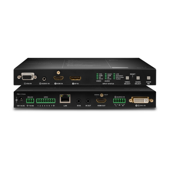
Page 12: Product Overview
Device is powered but not operational. DHCP settings, restore factory default settings, condition launching in Event AUTOSELECT LED Manager). Audio1 LIVE INFO: Both UMX-HDMI-140 and UMX-HDMI-140-Plus have the same HDMI HDMI Autoselect DVI-A Video look and controls on the front panel. DVI-D DVI-D... -
Page 13: Rear View
Connector section. WARNING! Always use the supplied 12V power adaptor. Warranty INFO: Both UMX-HDMI-140 and UMX-HDMI-140-Plus have the same void if damage occurs due to use of a different power source. GPIO 8-pole Phoenix connector for configurable look and controls on the rear panel. -
Page 14: Dvi-I Connector
ATTENTION! Only one (DVI-A or DVI-D) mode is available at a same 1 2 3 Left Lightware recommends the termination of LAN cables on the basis of time. You can use the Video Select button to choose the input Right TIA/EIA T 568 A or TIA/EIA T 568 B standards. -
Page 15: Ir Connector
IR detector and IR emitter can be connected to the receiver with TRS (Tip, Ring, and Sleeve) connectors. UMX-HDMI-140 is a universal audio/video switcher with analog/digital conversion and audio embedding They are also known as (3,5 mm or approx. 1/8”) audio jack, phone jack, phone plug, and mini-jack functions. -
Page 16: Port Diagram
UMX-HDMI-140 series– User's Manual 3.5. Port Diagram 3.6. Audio Interface The following figure describes the port diagram of the UMX-HDMI-140 series switcher: 3.6.1. Audio Input Modes The device can receive embedded digital audio signal on the HDMI, DisplayPort, and DVI-D input ports and Analog video analog audio signal on the Jack and the Phoenix input ports. -
Page 17: Audio Options - Example
3. Product Overview UMX-HDMI-140 series– User's Manual 3.6.2. Audio Options - Example 3.7. Video Interface 3.7.1. Video Input Modes ANALOG AUDIO IN 2 The device can receive digital video signal on the HDMI, DisplayPort, and DVI-D input ports and analog video signal on the VGA and the DVI-A input ports. -
Page 18: Automatic Input Selection - Example
Laptop VGA IN The serial port is in Event Manager mode. Priorities can be set in Lightware Device Controller software, see related settings in the Video Output section. INFO: All settings are available in the LDC software, see details in the RS-232 section. - Page 19 Create the following events in the event manager: E1. When the signal is present on O1 port of the UMX-HDMI-140-Plus, it sends a message 'PING' on P1 port of RS-232 to the VC codec. For more details see Message Sending via RS-232 Serial Port section.
-
Page 20: Ir Interface
HDMI IN HDMI OUT Technical Background DP IN The UMX-HDMI-140 switcher contains dedicated IR I/O connection and is able to transmit/receive IR signal via the IR emitter and detector units. The signal is in pronto HEX format. Audio1 LIVE RESET... -
Page 21: Gpio Interface
A/V system. independently based on needs of the application. UMX-HDMI-140-Plus model is able to send and receive CEC commands, on HDMI IN (I2) port towards the GPIO Options - Example source, on HDMI OUT (O1) port towards the sink. -
Page 22: Operation
UMX-HDMI-140 series– User's Manual 4.1. Front Panel Operation 4.2. Special Functions 4.1.1. Video Select Button 4.2.1. Customize Button Function The audio and input select function can be disabled by Lightware Device Controller (LDC) software or LW3 protocol command and the Audio1 LIVE RESET HDMI... -
Page 23: Control Lock
DVI-D Audio2 VIDEO AUDIO VIDEO AUDIO SHOW ▪ Lightware Device Controller (LDC) - you can connect to the device VGA IN AUDIO1 IN HDMI IN DP IN INPUT STATUS SELECT SELECT via our control software using Ethernet or RS-232 interface and Press the Audio Select and Show Me buttons together (within 100 ms) control or configure the device as you wish. -
Page 24: Software Control - Lightware Device Controller
The device can be controlled by a computer through the Ethernet and RS-232 Normal install Snapshot install port using Lightware Device Controller (LDC). The software can be installed The common way to start the software is double-click on the LDC Available for Windows and macOS Available for Windows on a Windows PC or macOS. -
Page 25: Establishing The Connection
5. Software Control - Lightware Device Controller UMX-HDMI-140 series– User's Manual 5.3. Establishing the Connection Step 3. Select the unit from the discovered Ethernet devices or under Serial devices; when the device is connected through RS-232 click on the Query button next to the desired serial port to display the Step 1. -
Page 26: Crosspoint Menu
5. Software Control - Lightware Device Controller UMX-HDMI-140 series– User's Manual 5.4. Crosspoint Menu When LDC finds the hardware, it determines the product type, and the LDC starts with the default page, showing the Crosspoint menu. Main menu The available menu items are displayed. -
Page 27: Port Properties Windows
5. Software Control - Lightware Device Controller UMX-HDMI-140 series– User's Manual 5.5. Port Properties Windows Port Tiles Available settings: The colors of the port tiles and the displayed icons represent different ▪ Mute/unmute the port; Clicking on the port tile opens the Port properties window. This section states and information: Lock/unlock the port;... -
Page 28: Digital Video Inputs
Clicking on the HDMI, DisplayPort, or DVI-D input port icon results UMX-HDMI-140-Plus model is able to send and receive Consumer list too (on the left side). Click on the Send button to opening the Port properties window. -
Page 29: Analog Audio Inputs
5. Software Control - Lightware Device Controller UMX-HDMI-140 series– User's Manual 5.5.4. Analog Audio Inputs 5.5.5. Digital Audio Inputs Port properties window of the AUDIO2 (Phoenix) input Port properties window of HDMI audio input Certain parameters of the analog audio input signal can be set as... -
Page 30: Video Output
5. Software Control - Lightware Device Controller UMX-HDMI-140 series– User's Manual 5.5.6. Video Output 5.5.7. Audio Output Available settings: ▪ Mute/unmute the port; Click on the output port to display its properties. The most important Certain parameters of the digital audio output signal can be set as information and settings are available from the panel. -
Page 31: Frame Detector
Frame detector window Color: Click on the desired color or use the sliders and press Lightware’s Frame Detector function works like a signal analyzer and the Set color button to store. makes possible to determine the exact video format that is present on the port, thus helps to identify many problems. -
Page 32: Edid Menu
5. Software Control - Lightware Device Controller UMX-HDMI-140 series– User's Manual 5.6. EDID Menu 5.6.1. EDID Operations Advanced EDID Management can be accessed by selecting the EDID menu. There are two panels: left one Changing Emulated EDID contains Source EDIDs, right one contains Destination places where the EDIDs can be emulated or copied. -
Page 33: Edid Summary Window
The software resolves the raw EDID and displays it as readable information to the user. All descriptors can be edited, and saved in an EDID file, or uploaded to the User memory. For more details about EDID Editor please visit our website (www.lightware.com) and download EDID Editor user's manual. -
Page 34: Creating An Edid - Easy Edid Creator
5.7.1. RS-232 Create Lightware introduced a wizard-like interface for fast and easy EDID creation. With Easy EDID Creator it is possible to create custom EDIDs in four simple steps. By clicking on the Create button below Source panel, Easy EDID Creator is opened in a new window. For more details about EDID Editor please visit our website (www.lightware.com) and download EDID Editor user's manual. -
Page 35: Message Recognizer
RS-232 Recognizer Example. When the UMX-HDMI-140-Plus has an active video signal, the switcher login the VC codec automatically. The signal presence triggers a bi-directional communication with the VC codec via RS-232: Step 1. Turn on the recognizer: Enable it on the P1 serial port. -
Page 36: Gpio
5. Software Control - Lightware Device Controller UMX-HDMI-140 series– User's Manual 5.7.3. GPIO 5.7.4. Ethernet GPIO tab in Control menu Ethernet tab in Control menu The GPIO port has 7 pins, which operate at TTL digital signal levels and can be controlled by LDC or protocol Two ports are displayed in the Ethernet settings: Local and CPU. -
Page 37: Infra
Step 4. Once the code is received, a new window pops up in LDC - learning completed. Click OK to continue. Step 5. Optionally type a unique name for the code in the Name text box. The default name is code#, e.g. code0. INFO: UMX-HDMI-140 model can handle the IR codes in hash format. IR codes window in Control menu... - Page 38 5. Software Control - Lightware Device Controller UMX-HDMI-140 series– User's Manual Ports Tab in UMX-HDMI-140-Plus Sending pronto hex codes (Little-endian format) Copy the raw, little endian-format IR code into the Send Pronto Hex entry field and click the Send button.
-
Page 39: Event Manager
5. Software Control - Lightware Device Controller UMX-HDMI-140 series– User's Manual 5.8. Event Manager 5.8.1. The Event Editor Press the Edit button in the desired Event line to open the Event editor window. The feature means that the device can sense changes on its ports and able to react according to the pre-defined settings. -
Page 40: Create Or Modify An Event
5. Software Control - Lightware Device Controller UMX-HDMI-140 series– User's Manual 5.8.2. Create or Modify an Event 5.8.3. Special Tools and Accessories Wizard Mode The Name of the Event The wizard mode lists the most common conditions and actions, so the The name of a port can be changed by typing the new name and clicking the Set button. -
Page 41: Clear One Or More Event(S)
In the current case the command is: PWR0\x0d\x0a The UMX-HDMI-140 is connected to a projector by the HDMI output port. The switcher is also connected to the projector by the RS-232 port and can send commands via the serial line. -
Page 42: Settings Menu
10, macOS, Linux. Compatible web browsers: Mozilla Firefox, Google Chrome, Apple Safari. ATTENTION! Please be sure that the computer is in the same network as the UMX-HDMI-140. If the computer has multiple Ethernet connections (for example Wi-Fi and LAN connections are used simultaneously) you will have to know the IP address for the one, that is used for controlling the switcher. -
Page 43: Front Panel
You can disable the functionality of the front panel buttons with marking the Lock front panel option. Configuration cloning of Lightware LW3 devices is a simple method that eliminates the need to repeatedly This is same method of the control lock made by the front panel buttons. See the details in the Control configure certain devices to have identical (non-factory) settings. -
Page 44: Save The Settings Of A Device (Backup)
5. Software Control - Lightware Device Controller UMX-HDMI-140 series– User's Manual 5.9.7. Save the Settings of a Device (Backup) 5.9.9. System Step 1. Apply the desired settings in the switcher (port parameters, crosspoint, etc.) Step 2. Select the Settings / Backup tab from the menu. -
Page 45: Advanced View Window
5. Software Control - Lightware Device Controller UMX-HDMI-140 series– User's Manual 5.10. Advanced View Window LW3 protocol help Pushing the button results a help window opening which describes the most important information about LW3 protocol commands in HTML format. -
Page 46: Lw2 Programmer's Reference
The device can be controlled through a reduced command set of LW2 protocol commands to ensure the compatibility <id> id number in 1 or 2 digit ASCII format with other Lightware products. The supported LW2 commands are described in this chapter. <id²> id number in 2 digit ASCII format... -
Page 47: View Firmware Version Of The Cpu
Command {FC} {f} {fc} Response (FW:<FW_VER><s>)CrLf Response (CF●<DESC>)CrLf (FW:1.0.0b4 r5) (CF UMX-HDMI-140 1.0.0b4 r5) (CF●<DESC>)CrLf Legend: <FW_VER> is the firmware version. It is followed by <s> string which may indicate special versions. … (CF END)CrLf 6.2.4. Connection Test ... -
Page 48: A/V Port Settings
6. LW2 Programmer's Reference UMX-HDMI-140 series– User's Manual 6.3. A/V Port Settings 6.3.3. Unmute Output Description: Unmute output <out>. 6.3.1. Switch an Input to the Output Following commands with <A/V/AV> option can take effect in multiple layers, according to their parameters. -
Page 49: View Connection State On The Output
6. LW2 Programmer's Reference UMX-HDMI-140 series– User's Manual 6.3.6. View Connection State on the Output 6.3.8. Change Video Autoselect Mode Description: Viewing the crosspoint state of the device; showing the input port numbers connected to the Description: The autoselect mode of the video outputs can be changed. -
Page 50: Change The Video Input Priorities
6. LW2 Programmer's Reference UMX-HDMI-140 series– User's Manual 6.3.10. Change the Video Input Priorities 6.4. Network Configuration Description: The settings of video input priority can be changed as follows. 6.4.1. Query the Current IP Status Format Example Description: IP address settings can be queried as follows. -
Page 51: Set The Gateway Address
6. LW2 Programmer's Reference UMX-HDMI-140 series– User's Manual 6.4.4. Set the Gateway Address Description: Gateway address can be set as follows. Format Example Command {IP_GATEWAY=<gateway_addr>} {ip_gateway=192.168.0.50} Response (IP_GATEWAY=<gateway_addr>)CrLf (IP_GATEWAY=192.168.0.50) Legend: <gateway_addr>: Four decimal octets separated by dots. -
Page 52: Lw2 Commands - Quick Summary
6. LW2 Programmer's Reference UMX-HDMI-140 series– User's Manual 6.6. LW2 Commands – Quick Summary Network Configuration See in General LW2 Commands Operation Command chapter See in Operation Command Query the Current IP Status 6.4.1 {IP_STAT=?} chapter Set the IP Address 6.4.2... -
Page 53: Lw3 Programmers' Reference
(Cr, ‘\r’) and line feed (Lf, ‘\n’) pair. It is organized as a tree structure that provides outstanding flexibility and user-friendly handling with ‘nodes’, ‘properties’ and ‘methods’. The Advanced View of the Lightware Device Controller software is the perfect tool for browsing and learning how the LW3 protocol can be used in practice. -
Page 54: Command Types
7. LW3 Programmers’ Reference UMX-HDMI-140 series– User's Manual 7.2.3. Command Types 7.2.4. Prefix Summary DEFINITION: The prefix is a 2-character long code that describes the type of the response. GET command The following prefixes are defined in the LW3 protocol: The GET command can be used to get the child nodes, properties and methods of a specific node. -
Page 55: Signature
7. LW3 Programmers’ Reference UMX-HDMI-140 series– User's Manual 7.2.7. Signature 7.2.9. Notifications about the Changes of the Properties DEFINITION: The signature is a four-digit-long hexadecimal value that can be optionally placed before When the value of a property is changed and the user is subscribed to the node, which the property belongs every command to keep a command and the corresponding responses together as a group. -
Page 56: System Commands
7. LW3 Programmers’ Reference UMX-HDMI-140 series– User's Manual 7.3. System Commands 7.3.4. Query the Firmware Version 7.3.1. Query the Product Name Command and Response Î GET·/SYS/MB.FirmwareVersion The name of the product is a read-only parameter and cannot be modified. -
Page 57: Lock The Front Panel Buttons
7. LW3 Programmers’ Reference UMX-HDMI-140 series– User's Manual 7.3.7. Lock the Front Panel Buttons 7.3.9. Dark Mode This command turns the Video and Audio LEDs off the on the front panel. Command and Response Î SET /MANAGEMENT/UI.ControlLock=<lock_status> Command and Response Í... -
Page 58: Video Port Settings
7. LW3 Programmers’ Reference UMX-HDMI-140 series– User's Manual 7.4. Video Port Settings The Most Common Received Port Status Responses INFO: Video port numbering can be found in the Input/Output Port Numbering section. 7.4.1. Query the Status of Source Ports... -
Page 59: Query The Status Of Destination Port
7. LW3 Programmers’ Reference UMX-HDMI-140 series– User's Manual 7.4.2. Query the Status of Destination Port 7.4.5. Query the Video Autoselect Settings Command and Response Command and Response Î GET·/MEDIA/VIDEO/XP.DestinationPortStatus Î GET·/MEDIA/VIDEO/XP.DestinationPortAutoselect pr·/MEDIA/VIDEO/XP.DestinationPortStatus=<out1_state>;<out2_state>;<…>;<out#_state> pr·/MEDIA/VIDEO/XP.DestinationPortAutoselect=<out1_set>;<out2_set>;<…>;<out#_set> Í Í The response contains 5 ASCII characters for each port. The first character indicates the mute/lock state, The response shows the settings of each output one by one. -
Page 60: Query The Input Port Priority
7. LW3 Programmers’ Reference UMX-HDMI-140 series– User's Manual 7.4.7. Query the Input Port Priority 7.4.9. Mute an Input Port Command and Response Command and Response Î GET·/MEDIA/VIDEO/XP.PortPriorityList Î CALL·/MEDIA/VIDEO/XP:muteSource(<in>) Í pr·/MEDIA/VIDEO/XP.PortPrioirtyList= <out1_list>;<out2_list>;<…>;<out#_list> Í mO·/MEDIA/VIDEO/XP:muteSource The response shows the priority of each output one after another. The priority number can be from 0 to 31;... -
Page 61: Mute Output
7. LW3 Programmers’ Reference UMX-HDMI-140 series– User's Manual 7.4.13. Mute Output 7.4.17. HDCP Setting (Input Port) HDCP capability can be enabled/disabled on the input ports, thus, non-encrypted content can be seen on a Command and Response non-HDCP compliant display. See more information in the HDCP Management section. -
Page 62: Hdcp Setting (Output Port)
7. LW3 Programmers’ Reference UMX-HDMI-140 series– User's Manual Test Pattern Resolution Example Î SET /MEDIA/VIDEO/O1.HdcpModeSetting=0 Command and Response Í pw /MEDIA/VIDEO/O1.HdcpModeSetting=0 SET·/MEDIA/VIDEO/<in>.FreeRunResolution=<tpg_resolution> Î 7.4.20. HDMI Mode Settings (Output Port) pw·/MEDIA/VIDEO/<in>.FreeRunResolution=<tpg_resolution> Í Parameters Command and Response Parameter SET·/MEDIA/VIDEO/<out>.HdmiModeSetting=<hdmi_mode>... -
Page 63: Audio Port Settings
7. LW3 Programmers’ Reference UMX-HDMI-140 series– User's Manual 7.5. Audio Port Settings The Most Common Received Port Status Responses INFO: Audio port numbering can be found in the Input/Output Port Numbering section. 7.5.1. Query the Status of Source Port... -
Page 64: Mute Audio Input
7. LW3 Programmers’ Reference UMX-HDMI-140 series– User's Manual 7.5.3. Mute Audio Input 7.5.7. Analog Audio Input Level Settings Command and Response Volume Î CALL·/MEDIA/AUDIO/XP:muteSource(<in>) Command and Response Í mO·/MEDIA/AUDIO/XP:muteSource SET·/MEDIA/AUDIO/<in>.Volume=<level> Î Example pw·/MEDIA/AUDIO/<in>.Volume=<level> Í Î CALL /MEDIA/AUDIO/XP:muteSource(I1) Parameters Í... -
Page 65: Network Configuration
7. LW3 Programmers’ Reference UMX-HDMI-140 series– User's Manual 7.6. Network Configuration 7.6.4. Change the IP Address (Static) 7.6.1. Query the DHCP State Command and Response SET·/MANAGEMENT/NETWORK.StaticIpAddress=<IP_address> Î Command and Response pw·/MANAGEMENT/NETWORK.StaticIpAddress=<IP_address> Í Î GET·/MANAGEMENT/NETWORK.DhcpEnabled pw·/MANAGEMENT/NETWORK.DhcpEnabled=<DHCP_state> Example Í Î SET /MANAGEMENT/NETWORK.StaticIpAddress=192.168.0.85 Parameters Í... -
Page 66: Change The Gateway Address (Static)
7. LW3 Programmers’ Reference UMX-HDMI-140 series– User's Manual 7.6.8. Change the Gateway Address (Static) 7.7.3. Databit Setting Command and Response Command and Response SET·/MANAGEMENT/NETWORK.StaticGatewayAddress=<gw_address> SET·/MEDIA/UART/P1.DataBits=<databit> Î Î pw·/MANAGEMENT/NETWORK.StaticGatewayAddress=<gw_address> pw·/MEDIA/UART/P1.DataBits=<databit> Í Í Example Parameters Î SET /MANAGEMENT/NETWORK.StaticGatewayAddress=192.168.0.5 <databit> 8 or 9 Í... -
Page 67: Parity Setting
/MEDIA/UART/P1.CommandInjectionStatus. Command and Response 7.8. RS-232 Recognizer SET·/MEDIA/UART/P1.Rs232Mode=<rs232_mode> Î INFO: This feature is available only in UMX-HDMI-140-Plus model. pw·/MEDIA/UART/P1.Rs232Mode=<rs232_mode> Í This tool is able to recognize the incoming RS-232 message. It stores the incoming serial data from the first Parameters bit, until the previously defined string (delimiter) or the elapsing timeout after the last bit. The last incoming serial string is saved in different formats (string, hex, and hash). -
Page 68: Set The Delimiter Hex
7. LW3 Programmers’ Reference UMX-HDMI-140 series– User's Manual 7.8.2. Set the Delimiter Hex 7.8.4. Query the Last Recognized Serial Message (Rx, RxHex, Hash) 7.8.5. Clear the Stored Last Recognized Serial Message When the delimiter hex string is detected in the incoming serial data, The recognized data is stored in string, hex and hash formats. -
Page 69: Set The Active Timeout
7. LW3 Programmers’ Reference UMX-HDMI-140 series– User's Manual 7.9. Infrared Port Configuration Parameters <recognized _hash> Fingerprint code, Max. 32 bit-long recognized data INFO: Infrared input and output port numbering can be found in the hash. Input/Output Port Numbering section. -
Page 70: Sending Message Via The Communication Ports
7. LW3 Programmers’ Reference UMX-HDMI-140 series– User's Manual 7.10. Sending Message via the Communication Ports Î CALL·/MEDIA/ETHERNET.tcpBinary(<IP_address>:<port_no>=<HEX_message>) Í mO·/MEDIA/ETHERNET:tcpBinary 7.10.1. Sending Message via TCP Port Example The device can be used for sending a message to a certain IP:port address. The three different commands Î... -
Page 71: Message Sending Via Rs-232 Serial Port
7. LW3 Programmers’ Reference UMX-HDMI-140 series– User's Manual 7.10.2.2. Sending a UDP Text (ASCII-format) 7.10.3.2. Sending a Text (ASCII-format) via RS-232 The command is for sending a text message in ASCII-format via UDP-protocol. This method does not allow The command is for sending a command message in ASCII-format. -
Page 72: Sending Cec Commands
7.10.5.2. Sending a CEC Command in Text Format Command and Response ATTENTION! CEC command sending feature is available in UMX-HDMI-140-Plus model. Î CALL /MEDIA/CEC/<port>:send(<command>) INFO: The hidden first 2 bytes of the CEC command is static, it refers to the logical address of the sender and the addressee. -
Page 73: Sending Pronto Hex Codes In Little-Endian Format Via Ir Port
Internet. The TIPS AND TRICKS: Learning raw IR code with a terminal program: Î CALL·/MEDIA/GPIO/<GPIO_port>:toggle() downloaded codes are mostly in little-endian format. Step 1. Connect to the UMX-HDMI-140 series device with a terminal Í pw·/MEDIA/GPIO/<GPIO_port>:toggle program. Example Step 2. -
Page 74: Edid Management
7. LW3 Programmers’ Reference UMX-HDMI-140 series– User's Manual 7.12. EDID Management INFO: Use the Manufacturer property to query the manufacturer and the MonitorName property to query the name of the monitor. 7.12.1. Query the Emulated EDIDs 7.12.4. Emulating an EDID to an Input Port... -
Page 75: Copy An Edid To User Memory
7. LW3 Programmers’ Reference UMX-HDMI-140 series– User's Manual 7.12.6. Copy an EDID to User Memory ATTENTION! The (User) EDID memory slot will be overwritten without notification even if it was not empty. Command and Response Î CALL·/EDID:copy(<source>:<destination>) Í... -
Page 76: Lw3 Quick Summary
7. LW3 Programmers’ Reference UMX-HDMI-140 series– User's Manual 7.13. LW3 Quick Summary Change the Autoselect Mode Î CALL·/MEDIA/VIDEO/XP:setDestinationPortAutoselect(<out>:<out_set>) System Commands Query the Input Port Priority Query the Product Name Î GET·/MEDIA/VIDEO/XP.PortPriorityList Î GET·/.ProductName Change the Input Port Priority Set the Device Label Î... - Page 77 7. LW3 Programmers’ Reference UMX-HDMI-140 series– User's Manual Audio Port Settings RS-232 Port Configuration Query the Status of Source Port Protocol Setting Î GET·/MEDIA/AUDIO/XP.SourcePortStatus SET·/MEDIA/UART/P1.ControlProtocol=<cont_protocol> Î Query the Status of Destination Port BAUD Rate Setting Î GET·/MEDIA/AUDIO/XP.DestinationPortStatus SET·/MEDIA/UART/P1.Baudrate=<baud_rate>...
- Page 78 7. LW3 Programmers’ Reference UMX-HDMI-140 series– User's Manual Query the Last Recognized Serial Message (ActiveRx, ActiveRxHex, ActiveHash) Sending a CEC Command in Text Format Î GET·/MEDIA/UART/RECOGNIZER.ActiveRx Î CALL /MEDIA/CEC/<port>:send(<command>) Î GET·/MEDIA/UART/RECOGNIZER.ActiveRxHex Send CEC Command in Hexadecimal Format Î...
-
Page 79: Firmware Upgrade
This chapter is meant to help customers perform firmware upgrades on our products by giving a few tips on how to start and by explaining the features of the Lightware Device Updater v2 (LDU2) software. To get the latest software ▪... -
Page 80: Firmware Upgrading Steps
Signal processing is not performed. Do not interrupt the firmware upgrade. If any problem occurs, reboot the unit and restart the process. Step 1. Connect the computer to the same network as the UMX-HDMI-140 is located. Run the LDU2 software. The discovered and known devices are being loaded. -
Page 81: Keeping The Configuration Settings
In the case of factory reset you can save the settings of the device in the Lightware Device Controller software and restore it later. See the details in the Backup (Configuration Cloning) section. -
Page 82: Troubleshooting
9. Troubleshooting UMX-HDMI-140 series– User's Manual At first, check front panel LEDs and take the necessary steps according to their states. For more information about status, LEDs refer to Front View Rear View sections. Symptom Root cause... - Page 83 9. Troubleshooting UMX-HDMI-140 series– User's Manual Symptom Root cause Action Refer to Symptom Root cause Action Refer to Audio signal Network No audio is Source audio volume is 4.2.5 No LAN Check the audio settings of the source.
-
Page 84: Technologies
(dynamic EDID emulation). information about additional Detailed Timings, audio capabilities, For example, the Lightware device can be set up to emulate a sink speaker allocation and HDMI capabilities. It is important to know that device, which is connected to one of the outputs. -
Page 85: Hdcp Management
HDCP enabling/disabling function: the HDCP capability can be Protected /DVI cable UMX-HDMI-140 HDCP-compliant disabled in the Lightware device. If HDCP is disabled, the connected content switcher sink source will detect that the sink is not HDCP capable, and turn off The layout is the same as in the previous case: non-HDCP compliant authentication. -
Page 86: Pixel Accurate Reclocking
Without reclocking, sparkles, noise, and jaggies appear on the image. Lightware’s sophisticated Pixel Accurate Reclocking technology fixes more problems than general TMDS reclocking. It removes not only intra-pair skew but inter-pair skew as well. The Pixel Accurate... -
Page 87: Appendix
11. Appendix UMX-HDMI-140 series– User's Manual 11.1. Specification Color space ..........RGB, YCbCr 4:4:4, YcbCr 4:2:2 Max. video resolutions .........1600x1200@60 Hz, 36 bit General ..............1920x1080@120Hz, 24 bit Compliance ..................CE ...............3840x2160@30 Hz, 24 bit EMI/EMC ......IEC/EN 55035:2017, IEC/EN 55032:2015 Audio formats ........8 channel PCM, Dolby TrueHD... -
Page 88: Content Of Backup File
11. Appendix UMX-HDMI-140 series– User's Manual 11.2. Content of Backup File DVI-I Input with DVI-A support Analog Audio Input (Phoenix) Connector type ..............29-pole, DVI-I Connector type ..........5-pole Phoenix connector The backup file contains numerous settings and parameters saved from the device. -
Page 89: Input/Output Port Numbering
11. Appendix UMX-HDMI-140 series– User's Manual 11.3. Input/Output Port Numbering Front View The following table contains the input and output ports with their ID numbers which shall be used in protocol Audio1 LIVE RESET commands. HDMI HDMI... -
Page 90: Audio Cable Wiring Guide
Symmetric audio is most often referred to as balanced audio, as opposed to asymmetric, which is referred to as unbalanced audio. Lightware products are usually built with 5-pole Phoenix connectors so we would like to help users assembling their own audio cables. -
Page 91: Wiring Guide For Rs-232 Data Transmission
11. Appendix UMX-HDMI-140 series– User's Manual 11.6. Wiring Guide for RS-232 Data Transmission 11.7. Factory Default Settings UMX-HDMI-140 is built with 3-pole Phoenix connector. See the below Parameter Setting/Value Parameter Setting/Value examples of connecting to a DCE (Data Circuit-terminating Equipment) -
Page 92: Factory Edid List
11. Appendix UMX-HDMI-140 series– User's Manual 11.9. Factory EDID List Mem. Resolution Type Mem. Resolution Type 1364 x 768 @ 50.00 2048 x 1536 @ 60.00 Mem. Resolution Type Mem. Resolution Type 1364 x 768 @ 59.94 2048 x 1536 @ 75.00... -
Page 93: Further Information
1.4. Product failures from six (6) months to the end of the warranty period will either be repaired or replaced at the discretion of Lightware. If Lightware chooses to replace the product then the replacement will be warranted for the remainder of the original unit’s warranty period.
Need help?
Do you have a question about the UMX-HDMI-140 and is the answer not in the manual?
Questions and answers