Table of Contents
Advertisement
Quick Links
Advertisement
Table of Contents
Troubleshooting

Related Manuals for Lightware UCX Series


Summary of Contents for Lightware UCX Series
- Page 1 User’s Manual UCX-4x2-HC30 UCX-4x2-HC30D Universal Switcher v1.4 04-05-2021...
- Page 2 UCX series – User's Manual Important Safety Instructions Waste Electrical & Electronic Equipment Common Safety Symbols WEEE Class II apparatus construction. Symbol Description This marking shown on the product or its literature, The equipment should be operated only from the power source indicates that it should not be disposed with other indicated on the product.
- Page 3 The following symbols and markings are used in the document: All presented functions refer to the indicated products. The descriptions Lightware Visual Engineering supports green technologies and have been made during testing these functions in accordance with the Eco-friend mentality. Thus, this document is made for digital usage...
-
Page 4: Table Of Contents
2. PRODUCT OVERVIEW ..............10 5.6. Ethernet Interface ..............33 7.3.4. Command Types ................60 2.1. Front View ...................11 7.3.5. Prefix Summary ................61 6. SOFTWARE CONTROL - LIGHTWARE DEVICE CONTROLLER ..35 2.2. Rear View ..................11 7.3.6. Error Messages ................61 6.1. Install and Upgrade ..............36 7.3.7. Escaping ..................61 3. - Page 5 UCX series – User's Manual 7.6. Welcome Screen Settings ............68 7.11. EDID Management ..............76 10. TECHNOLOGIES ................92 7.6.1. Display Welcome Screen Image ............. 68 7.11.1. Query the Emulated EDIDs ............76 10.1. EDID Management ..............93 7.6.2. Display Welcome Screen Text ............68 7.11.2. Query the Validity of a Dynamic EDID ..........
-
Page 6: Introduction
1. Introduction UCX series – User's Manual I ntroduction Thank you for choosing Lightware’s The Taurus UCX-series devices. In the first chapter we would like to introduce the device highlighting the most important features in the below listed sections: ç Description ç... -
Page 7: Description
1.1. Description 1.2. Box Contents Lightware’s universal switcher enhances and extends the possibilities of a meeting room and allows meeting participants to easily use their own devices such as laptops, and preferred video conference platforms while also to utilize the available assets of the meeting space, just like the HDMI displays, room cameras and other USB peripherals. -
Page 8: Features Of The Device
1. Introduction UCX series – User's Manual 1.4. Features of the Device Common Features USB 3.1 Switch 3D and 4K Support The USB 3.1 layer provides the switching of four external USB peripherals (e.g. webcamera, High bandwidth allows extension of resolutions up to 4K and even 3D sources and displays are speakerphone, multitouch display, etc.) to four independent host computers or laptops. -
Page 9: Typical Application
1. Introduction UCX series – User's Manual 1.5. Typical Application UCX-4x2-HC30 - Example 2. UCX-4x2-HC30 - Example 1. Applied firmware package: v1.1.0b7 | LDC software: v2.5.4b3... -
Page 10: Product Overview
2. Product Overview UCX series – User's Manual Product Overview The following sections are about the physical structure of the device, input/ output ports and connectors: ç Front View ç Rear View Applied firmware package: v1.1.0b7 | LDC software: v2.5.4b3... -
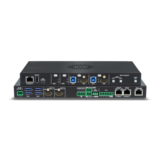
Page 11: Front View
2. Product Overview UCX series – User's Manual 2.1. Front View 2.2. Rear View UCX-4x2-HC30 UCX-4x2-HC30 5 6 7 1 2 3 SERVICE INPUT SELECT IN 1 IN 2 IN 3 IN 4 DC IN Tx2 Rx2 RS-232... -
Page 12: Front Panel Control
3. Front Panel Control UCX series – User's Manual Front Panel Control The following sections are about front panel operation of the device and the status LEDs: ç Button Functionality ç Status LEDs Applied firmware package: v1.1.0b7 | LDC software: v2.5.4b3... -
Page 13: Button Functionality
3. Front Panel Control UCX series – User's Manual 3.1. Button Functionality 3.2. Status LEDs 3.1.1. Video Source Selection 3.2.1. Front Panel LEDs Push OUT1 to select the video input for the HDMI OUT1 port. Arrangement of the status LEDs... -
Page 14: Ethernet Status Leds
3. Front Panel Control UCX series – User's Manual 3.2.3. Ethernet Status LEDs 3.2.4. Dante Audio Out (in UCX-4x2-HC30D model) ® Left LED HW version DIFFERENCE: The color of the left Ethernet LED is red DIFFERENCE: UCX-4x2-HC30D model has Dante Audio Output. -
Page 15: Installation
4. Installation UCX series – User's Manual Installation ç Mounting Options ç Electrical Connections ç Powering Options ç Power Delivery ç USB-C Cable Recommendation ç Connecting Steps Applied firmware package: v1.1.0b7 | LDC software: v2.5.4b3... -
Page 16: Mounting Options
The examples demonstrate the applications of UD Kit accessories: #new To mount the switcher Lightware supplies optional accessories for different usage. There are two kinds of mounting kits with similar fixing method. The switcher has two mounting holes with inner thread on Step 1. -
Page 17: Ventillation
4. Installation UCX series – User's Manual Step 4. Fix the UD Mounting plate F100 and UD Mounting PSU F100 under the desk by fastening the screws. INFO: UD Mounting plate F100 and UD Mounting PSU F100 do not contain the fixing screws, they can be purchased from the local hardware store. -
Page 18: Electrical Connections
High Speed Data Transfer for USB 2.0 and USB 1.1 Wiring of LAN Cables The pinout of the USB-C connector Lightware recommends the termination of LAN cables on the basis of TIA/EIA T 568 A or TIA/EIA T 568 B standards. ATTENTION! USB-C functionality and speed depend on the cable and the device. -
Page 19: Ocs Connector
4. Installation UCX series – User's Manual 4.2.5. OCS Connector 4.2.6. GPIO - General Purpose Input/Output Ports The switcher is supplied a 3.81mm 3-pole 90° Reversed Gender Plug Phoenix connector which is used for The switcher is supplied a 8-pole Phoenix connector with six GPIO pins, which operates at TTL digital signal ®... -
Page 20: Powering Options
Allows negotiation of up to 60 W of power delivery to supply or Power Delivery (up to 60 W) The UCX series devives are designed to provide power delivery for the connected device over the USB-C charge equipment connected to a USB-C port. -
Page 21: Power Data Objects (Usb-C)
5A charging capability is not required. All USB Type-C cables should support at least 3A (up to 60W) charging. ▪ When more than 2m long cable is needed, please contact the sales (sales@lightware.com) for the cable recommendation. Powering Handshake Dual-Role Power #new With USB-C the connector is the same on all products. -
Page 22: Connecting Steps
4. Installation UCX series – User's Manual 4.6. Connecting Steps Room PC Connect a USB-C source (e.g. BYOD laptop) to the USB-C input port. USB-C BYOD BYOD Speaker The applied cable shall be certified for USB 3.1 Gen1 (5Gbps) and Displayport Alternate mode Laptop 1. -
Page 23: Device Concept
5. Device Concept UCX series – User's Manual Device Concept The following chapter describes the features of the device with a few real-life examples. ç Universal Switcher Concept ç USB Interface ç Video Interface ç The Autoselect Feature ç... -
Page 24: Universal Switcher Concept
Taurus UCX series supports USB 3.1 Gen1 USB Superspeed Data (5 Gbps) Lightware’s universal switcher exploits the USB-C connectivity for a simplified transmission of 4K video, (max. 5 Gbps data speed) on their USB-C USB High Speed Data (480 Mbps) -
Page 25: Usb Data - Usb 3.1 Gen1 Interface
This function is available only for USB type C connectors. See more details in DisplayPort Alternate Mode section. USB Port Diagram Host detection One host is available at the same time. Taurus UCX series devices give a feedback about the connected USB-C (5 Gbps) hosts. USB 3.1 Gen1 (5 Gbps) USB 2.0 mini In case of USB Type-B ports: When the 5V is detected on USB Vbus, the Connected property becomes true. -
Page 26: Usb Service Ports - Usb 2.0 Interface
Host 4 1000 mA Device 4 The SERVICE-labelled USB-A connector and mini B-type connector is designed for service function. It will be USB features in Taurus UCX series added by future firmware update. Application of USB - Example USB-A (D1) -
Page 27: Video Interface
5. Device Concept UCX series – User's Manual 5.3. Video Interface 5.3.1. DisplayPort Alternate Mode USB-C sources sends Displayport signal for video transmission. Summary of Video Ports Displayport Alternate mode allows using the DisplayPort Alternate Mode USB-C cable instead of DisplayPort cable... -
Page 28: Displayport Alternate Mode And Usb 3.X Mixed
ATTENTION! The autoselect function remains active after the manual crosspoint switching. This operation DP Lanes DP1.2 (5.4 Gbps) mode works contrary to the other Lightware matrix switchers or extenders). HBR2 USB 3.1 (5 Gbps) Disable autoselect The crosspoint state change only happens manually. - Page 29 5. Device Concept UCX series – User's Manual Automatic Input Selection- Example 1. The individual input settings are the following: The Welcome screen appears on the Monitor 1. (O1) when no active source connected. O1: I1 priority:1; I2 priority: disabled; I3 priority:2; I4 priority: disabled; I5 priority:3 O2: I1 priority: disabled;...
- Page 30 USB and Displayport, or one USB cable (USB-B or USB-C) for data and one HDMI cable for video can be used. O1: I1 priority:1; I2 priority: disabled; I3 priority:2; I4 priority: disabled; I5 priority:3 The Taur UCX series device will switch both USB and video layers accordingly. Automatic Input Selection - Example 3.
-
Page 31: Audio Interface
5. Device Concept UCX series – User's Manual 5.5. Audio Interface Case 3. When the BYOD laptop uses HDMI for video and USB-C for data. Summary of Audio Ports #new Audio Outputs Analog audio de-embedding HDMI IN 3... -
Page 32: Dante ® Audio Interface
5. Device Concept UCX series – User's Manual 5.5.2. Dante Audio Interface ® Settings and Signal Routing DIFFERENCE: The following section refers to the UCX-4x2-HC30D model. #new UCX-4x2-HC30D model contains a special module that allows de-embedding the audio stream of the... - Page 33 5. Device Concept UCX series – User's Manual Device Settings The discovered Dante -compatible devices are displayed with middle-blue color. Double-click on the name ® to open the device settings. The default device name is: UCX-D-<Dante_MAC_address_last 6_characters>...
-
Page 34: Ethernet Interface
10/100 10/100 Ethernet Ethernet The device can be controlled via Ethernet (standard RJ45 connector). This interface supports: Configure the device with Lightware Device Controller. For more information about the LDC, see ▪ Software Control - Lightware Device Controller section. ▪... -
Page 35: Software Control - Lightware Device Controller
S oftware Control - Lightware Device Controller The device can be controlled by a computer through Ethernet by the Lightware Device Controller (LDC). The software can be installed on a Windows PC or macOS. The application and the User’s Manual can be downloaded from www.lightware.com. -
Page 36: Install And Upgrade
The Device Discovery window appears automatically and the program checks the available updates on The window can be zoomed to a specific value to fit to the resolution of the desktop (higher/lower). '1' is the Lightware’s website and opens the update window if LDC updates are found. default value (100%). -
Page 37: Establishing The Connection
6. Software Control - Lightware Device Controller UCX series – User's Manual 6.3. Establishing the Connection Change IP Address Step 1. Connect the device to a computer via Ethernet. To modify IP address settings quickly it is not necessary to enter the device's settings/network menu, you can set them by clicking Step 2. -
Page 38: Ldc Layout
6. Software Control - Lightware Device Controller UCX series – User's Manual 6.4. LDC Layout ATTENTION! Up to the v1.0.1b1 firmware version and v2.5.3b3 LDC version, the older LDC layout can be seen. From the 1.1.0b7 firmware version and v2.5.4b3 LDC the LDC design changed as it is seen in this chapter. -
Page 39: Video & Audio Crosspoint
6. Software Control - Lightware Device Controller UCX series – User's Manual 6.5. Video & Audio Crosspoint #crosspoint #switch Main menu The available menu items are displayed. The active one is showed with dark grey background color. -
Page 40: Port Tiles
6. Software Control - Lightware Device Controller UCX series – User's Manual 6.5.1. Port Tiles The colors of the port tiles and the displayed icons represent different states and information: Port name Port icon Port number Signal present... -
Page 41: Port Properties Window
6. Software Control - Lightware Device Controller UCX series – User's Manual 6.6. Port Properties Window General Port name Clicking on the port tile opens the Port properties window. This section shows the available settings and status information by port types. -
Page 42: Usb-C Inputs
6. Software Control - Lightware Device Controller UCX series – User's Manual 6.6.2. USB-C Inputs Video Status This section gives a feedback about the current video stream: Clicking on the USB-C video input port icon results opening the Port properties window. The most important information and settings are available from the panel. - Page 43 6. Software Control - Lightware Device Controller UCX series – User's Manual DisplayPort Link USB-C input port properties window INFO: The USB-C source sends Displayport video signal, so the video setting options of the USB-C port are similar to the DisplayPort.
-
Page 44: Hdmi Video Input
6. Software Control - Lightware Device Controller UCX series – User's Manual 6.6.3. HDMI Video Input Available settings and tools Port name Clicking on the HDMI video input port icon results opening the Port properties window. The most important information and settings are available from the panel. -
Page 45: Hdmi Video Output
6. Software Control - Lightware Device Controller UCX series – User's Manual 6.6.4. HDMI Video Output Available settings and tools General Port name The name of a port can be changed by typing the new name and clicking on the Set button. The following characters are allowed when naming: Letters (A-Z) and (a-z), hyphen (-), underscore (_), numbers (0-9), and dot (.). -
Page 46: Embedded Audio Input
6. Software Control - Lightware Device Controller UCX series – User's Manual 6.6.5. Embedded Audio Input Autoselect Autoselect feature makes possible switching input to the output without human intervention. The crosspoint state changes the based on the active input signals. -
Page 47: Analog Audio Output
▪ Volume: from 100 to 0%, in step 1% (0 dB to -95.625 dB, in step 0.375 dB (default is 0 dB)); Lightware’s Frame Detector function works like a signal analyzer and makes possible to determine the exact ▪ Balance: from -100 to +100, in step 1 (default is 0 = center). -
Page 48: Usb Crosspoint
6. Software Control - Lightware Device Controller UCX series – User's Manual 6.7. USB Crosspoint 6.7.1. USB-C Port Properties In USB crosspoint tab, the connection between the of the upstream ports (USB-C and USB-B ports) and the USB hub (USB-A ports) can be set. -
Page 49: Usb-B Port Properties
6. Software Control - Lightware Device Controller UCX series – User's Manual 6.7.2. USB-B Port Properties USB-C Power Limit Choose a powering option from the drop-down menu: #power ▪ Equal output power: both USB-C ports supplies max. 30W power. - Page 50 6. Software Control - Lightware Device Controller UCX series – User's Manual USB Hub Properties Autoselect #autoselect # usbautoselect #new For more details about this feature see Autoselect section. Autoselect settings: Disable autoselect / Follow video / First detect / Last detect mode / Individual input...
-
Page 51: Edid Menu
6. Software Control - Lightware Device Controller UCX series – User's Manual 6.8. EDID Menu 6.8.1. EDID Operations Advanced EDID Management can be accessed by selecting the EDID menu. There are two panels: left one Changing Emulated EDID contains Source EDIDs, right one contains Destination places where the EDIDs can be emulated or copied. -
Page 52: Edid Summary Window
The software resolves the raw EDID and displays it as readable information to the user. All descriptors can be edited, and saved in an EDID file, or uploaded to the User memory. For more details about EDID Editor please visit our website (www.lightware.com) and download the EDID Editor Application note. -
Page 53: Creating An Edid - Easy Edid Creator
Since above mentioned Advanced EDID Editor needs more complex knowledge about EDID, 6.10. Ethernet Lightware introduced a wizard-like interface for fast and easy EDID creation. With Easy EDID Creator it is possible to create custom EDIDs in four simple steps. By clicking on the Create button below Source panel, Easy EDID Creator is opened in a new window. -
Page 54: Gpio
6. Software Control - Lightware Device Controller UCX series – User's Manual 6.10.1. GPIO Interval Interval section is designed for setting the chosen GPIO pin to the specified level for a specified time. DIFFERENCE: This feature is available only from FW package 1.1.0b7. -
Page 55: Settings Menu
6. Software Control - Lightware Device Controller UCX series – User's Manual 6.11. Settings Menu 6.11.2. Network 6.11.1. Status Network tab in Settings menu IP address and DHCP settings can be set on this tab. Always press the Apply settings button to save changes. -
Page 56: System
6. Software Control - Lightware Device Controller UCX series – User's Manual 6.11.3. System Clone configuration #new DIFFERENCE: This feature is available only from FW package 1.1.0b7. Clone configuration makes possible saving all the LW3 settings, custom scripts and welcome screen image and upload to another device. -
Page 57: Advanced View Window
6. Software Control - Lightware Device Controller UCX series – User's Manual 6.12. Advanced View Window LW3 protocol help Pushing the button results a help window opening which describes the most important information about LW3 protocol commands in HTML format. -
Page 58: Lw3 Programmers' Reference
7. LW3 Programmers’ Reference UCX series – User's Manual L W3 Programmers’ Reference The device can be controlled through Lightware 3 (LW3) protocol commands to ensure the compatibility with other Lightware products. The supported LW3 commands are described in this chapter. ç Overview ç... -
Page 59: Overview
‘nodes’, ‘properties’ and ‘methods’. The V1 MEDIA Advanced View of the Lightware Device Controller software is the perfect tool for browsing and learning how VIDEO the LW3 protocol can be used in practice. -
Page 60: Legend For The Control Commands
7. LW3 Programmers’ Reference UCX series – User's Manual 7.3.3. Legend for the Control Commands 7.3.4. Command Types Command and Response – Example GET command ç GET·/V1/MEDIA/VIDEO/I2.SignalPresent The GET command can be used to get the child nodes, properties and methods of a specific node. It can also pr·/V1/MEDIA/VIDEO/I2.SignalPresent=<signal_present>... -
Page 61: Prefix Summary
7. LW3 Programmers’ Reference UCX series – User's Manual 7.3.5. Prefix Summary 7.3.8. Signature DEFINITION: The prefix is a 2-character long code that describes the type of the response. DEFINITION: The signature is a four-digit-long hexadecimal value that can be optionally placed before every command to keep a command and the corresponding responses together as a group. -
Page 62: Notifications About The Changes Of The Properties
7. LW3 Programmers’ Reference UCX series – User's Manual 7.3.10. Notifications about the Changes of the Properties When the value of a property is changed and the user is subscribed to the node, which the property belongs to, an asynchronous notification is generated. This is notification is called as the ‘change message’. The format of such a message is very similar to the response for the GET command: æ... -
Page 63: System Commands
7. LW3 Programmers’ Reference UCX series – User's Manual 7.4. System Commands 7.4.4. Querying the Firmware Package Version Command and Response #firmwareversion 7.4.1. Set the Device Label ç GET·/V1/MANAGEMENT/UID/PACKAGE.Version INFO: The device label can be changed to a custom text in the Status tab of the LDC software. -
Page 64: Video Port Settings - General
7. LW3 Programmers’ Reference UCX series – User's Manual 7.5. Video Port Settings - General 7.5.3. Lock the Video Port Command and Response 7.5.1. Switch Video Input SET·/V1/MEDIA/VIDEO/XP/<port>.Lock=<locked_state> ç Command and Response pw·/V1/MEDIA/VIDEO/XP/<port>.Lock=<locked_state> æ ç CALL·/V1/MEDIA/VIDEO/XP:switch(<in>:<out>) Parameters æ mO·/V1/MEDIA/VIDEO/XP:switch=... -
Page 65: Set The Autoselect Policy
7. LW3 Programmers’ Reference UCX series – User's Manual 7.5.5. Set the Autoselect Policy 7.5.7. Change the Input Port Priority Command and Response Command and Response SET·/V1/MEDIA/VIDEO/AUTOSELECT/<out>.Policy=<autoselect_mode> SET·/V1/MEDIA/VIDEO/AUTOSELECT/<out>/<in>.Priority=<prio_num> ç ç pw·/V1/MEDIA/VIDEO/AUTOSELECT/<out>.Policy=<autoselect_mode> pw·/V1/MEDIA/VIDEO/AUTOSELECT/<out>/<in>.Priority=<prio_num> æ æ Parameters Parameters Parameter Parameter description... -
Page 66: Query The Connected Destinations
7. LW3 Programmers’ Reference UCX series – User's Manual 7.5.9. Query the Connected Destinations 7.5.12. HDCP Setting (Input Port) Command and Response HDCP capability can be set on the input ports, thus, non-encrypted content can be seen on a non-HDCP compliant display. -
Page 67: Embeddedaudiopresent
7. LW3 Programmers’ Reference UCX series – User's Manual 7.5.14. EmbeddedAudioPresent 7.5.16. OutputSignalType ç GET·/V1/MEDIA/VIDEO/<port>.EmbeddedAudioPresent Command and Response #signaltype pr·/V1/MEDIA/VIDEO/<port>.EmbeddedAudioPresent=<embedded_state> æ SET·/V1/MEDIA/VIDEO/<out>.OutputSignalType=<signal_type> ç Parameters pw·/V1/MEDIA/VIDEO/<out>.OutputSignalType=<signal_type> æ Parameter Parameter description Values Value description Parameters <embedded_state> It shows if the video There is embedded audio in the video signal. -
Page 68: Welcome Screen Settings
7. LW3 Programmers’ Reference UCX series – User's Manual 7.6. Welcome Screen Settings 7.6.4. Reset Welcome Screen Image This command restores the original welcome screen image. 7.6.1. Display Welcome Screen Image Command and Response Command and Response #welcomescreen ç CALL·/V1/MEDIA/VIDEO/I5/WELCOMESCREEN:resetImage() SET·/V1/MEDIA/VIDEO/I5/WELCOMESCREEN.ImageEnabled=<image_state>... -
Page 69: Query The Connected Source
7. LW3 Programmers’ Reference UCX series – User's Manual 7.8.2. Query the Connected Source 7.8.5. Set the Followed Video Port to Autoselect Command and Response Command and Response ç GET·/V1/MEDIA/AUDIO/XP/O3.ConnectedSource SET·/V1/MEDIA/AUDIO/AUTOSELECT/O3.VideoFollowPort=<out> ç pw·/V1/MEDIA/AUDIO/XP/O3.ConnectedSource=<audio_in> pw·/V1/MEDIA/AUDIO/AUTOSELECT/O3.VideoFollowPort=<out> æ ç Example Parameters ç... -
Page 70: Mute The Audio Port 2
7. LW3 Programmers’ Reference UCX series – User's Manual 7.8.10. Analog Audio Output Volume (dB) Setting INFO: All inputs and analog output ports have a mute property in the audio XP (e.g. /V1/MEDIA/AUDIO/ XP/I1.Mute). Outputs have a separate mute function within the port node as well:... -
Page 71: Analog Audio Output Level Settings By Steps (Db)
7. LW3 Programmers’ Reference UCX series – User's Manual 7.8.13. Analog Audio Output Level Settings by Steps (dB) 7.9. USB Port Settings Command and Response #analogaudio #volume 7.9.1. Switch USB Input CALL·/V1/MEDIA/AUDIO/O3:stepVolumedB(<step>) ç Command and Response #usb æ m0·/V1/MEDIA/AUDIO/O3:stepVolumedB= ç... -
Page 72: Query The Connected Destinations
7. LW3 Programmers’ Reference UCX series – User's Manual 7.9.3. Query the Connected Destinations 7.9.5. Setting the 5V Sending to the USB Peripherals Command and Response #autoselect The 5V power towards the USB A-type ports can be enabled or disabled as follows: ç... -
Page 73: Set The Usb Autoselect Policy
7. LW3 Programmers’ Reference UCX series – User's Manual 7.9.6. Set the USB Autoselect Policy Example ç SET /V1/MEDIA/USB/AUTOSELECT/H1/U1.Included=true DIFFERENCE: Last detect and first detect mode is available only from FW package 1.1.0b7. æ pw /V1/MEDIA/USB/AUTOSELECT/H1/U1.Included=true Command and Response #new 7.9.9. Change the USB Port Priority... -
Page 74: Usb Port Settings - Usb-C Related Commands
7. LW3 Programmers’ Reference UCX series – User's Manual 7.10. USB Port Settings - USB-C Related Commands 7.10.3. Query the Host Alternate Mode Support Command and Response 7.10.1. Set USB-C Power ç GET·/V1/MEDIA/USB/<usb-c_port>.HostSupportsDpAltMode Command and Response #power pr·/V1/MEDIA/USB/<usb-c_port>.HostSupportsDpAltMode=<altmode_support> æ... -
Page 75: Query The Port Data Role
7. LW3 Programmers’ Reference UCX series – User's Manual 7.10.5. Query the Port Data Role 7.10.7. Set Port Power Role Command and Response Command and Response ç GET·/V1/MEDIA/USB/<usb_port>.ActivePortDataRole SET·/V1/MEDIA/USB/<usb-c_port>.PortPowerRoleSetting=<power_role> ç pr·/V1/MEDIA/USB/<usb_port>.ActivePortDataRole=<data_role> pw·/V1/MEDIA/USB/<usb_port>.PortPowerRoleSetting=<power_role> æ æ Parameters Parameters Parameter Parameter... -
Page 76: Edid Management
7. LW3 Programmers’ Reference UCX series – User's Manual 7.11. EDID Management 7.11.4. Emulating an EDID to an Input Port Command and Response 7.11.1. Query the Emulated EDIDs ç CALL·/V1/EDID:switch(<source>:<destination>) Command and Response #edid æ mO·/V1/EDID:switch ç GET·/V1/EDID.EdidStatus Parameters æ... -
Page 77: Copy An Edid To User Memory
7. LW3 Programmers’ Reference UCX series – User's Manual 7.11.6. Copy an EDID to User Memory 7.11.8. Resetting the Emulated EDIDs Command and Response Command and Response ç CALL·/V1/EDID:copy(<source>:<destination>) ç CALL·/V1/EDID:reset() æ mO·/V1/EDID:copy æ mO·/V1/EDID:reset Parameters Parameters Parameter... -
Page 78: Ethernet Port Configuration
7. LW3 Programmers’ Reference UCX series – User's Manual 7.12. Ethernet Port Configuration 7.12.3. Change the Subnet Mask (Static) Command and Response #ipaddress 7.12.1. Set the DHCP State SET·/V1/MANAGEMENT/NETWORK.StaticNetworkMask=<netmask> ç ATTENTION! When you change a network property the new value is stored but the applySettings method pw·/V1/MANAGEMENT/NETWORK.StaticNetworkMask=<netmask>... -
Page 79: Gpio Port Configuration
7. LW3 Programmers’ Reference UCX series – User's Manual 7.13. GPIO Port Configuration 7.13.4. Setting the Output Level of a GPIO Pin Command and Response DIFFERENCE: GPIO-related commands are available only from FW package 1.1.0b7. ç SET·/V1/MEDIA/GPIO/<port>.Output(<value>) 7.13.1. Querying the Direction of a GPIO Pin æ... -
Page 80: Ocs Port Configuration
7. LW3 Programmers’ Reference UCX series – User's Manual 7.14. OCS Port Configuration 7.14.3. Querying the Reported OCS State Command and Response DIFFERENCE: Occupancy sensor-related commands are available only from FW package 1.1.0b7. ç GET·/V1/MEDIA/OCS/P1.State 7.14.1. Querying the Input Level of an OCS Pin pr·/V1/MEDIA/OCS/P1.State=<status>... -
Page 81: Lw3 Commands - Quick Summary
7. LW3 Programmers’ Reference UCX series – User's Manual 7.15. LW3 Commands - Quick Summary Query the Connected Destinations ç GET·/V1/MEDIA/VIDEO/XP/<n>.ConnectedDestinations System Commands Query the Input Switchable Ability Set the Device Label GET·/V1/MEDIA/VIDEO/XP/<out>/SWITCHABLE.<in> ç SET·/V1/MANAGEMENT/LABEL.DeviceLabel=<custom_name> ç SignalPresent Reset the Device ç... - Page 82 7. LW3 Programmers’ Reference UCX series – User's Manual Audio Port Settings USB Port Settings Switch Audio Input Switch USB Input ç CALL·/V1/MEDIA/AUDIO/XP:switch(<audio_in>:O3) ç CALL·/V1/MEDIA/USB/XP:switch(<host>:H1) Query the Connected Source Query the Connected Source ç GET·/V1/MEDIA/AUDIO/XP/O3.ConnectedSource ç GET·/V1/MEDIA/USB/XP/H1.ConnectedSource...
- Page 83 7. LW3 Programmers’ Reference UCX series – User's Manual Set Port Power Role GPIO Port Configuration SET·/V1/MEDIA/USB/<usb-c_port>.PortPowerRoleSetting=<power_role> Querying the Direction of a GPIO Pin ç EDID Management ç GET·/V1/MEDIA/GPIO/<port>.Direction Setting the Direction of a GPIO Pin Query the Emulated EDIDs ç...
-
Page 84: Firmware Upgrade
This chapter is meant to help customers perform firmware upgrades on our products by giving a few tips on how to start and by explaining the features of the Lightware Device Updater v2 (LDU2) software. To get the latest software and firmware pack can be downloaded from www.lightware.com. -
Page 85: Introduction
8.2. Preparation may exist for all users installed for all users Most Lightware devices can be controlled over more interfaces (e.g. Ethernet, USB, RS-232). But the firmware ATTENTION! Using the default Normal install is highly recommended. can be upgraded usually over one dedicated interface, which is the Ethernet in most cases. -
Page 86: Running The Software
At startup, the software checks if a newer version is available on the web. Main Screen When the software is started by the shortcut, the device discovery screen SEARCH FOR DEVICES appears. Press the Search for devices button to start finding the Lightware devices: Legend of the Icons IP address editor The IP address of the device can be changed in the pop-up window. -
Page 87: The Upgrading Steps
8. Firmware Upgrade UCX series – User's Manual 8.4. The Upgrading Steps INFO: If you start the upgrade by double-clicking on the LFP file, above screen will be loaded right away. The Meaning of the Symbols ATTENTION! While the firmware is being upgraded, the normal operation mode is suspended as the device is switched to bootload mode. -
Page 88: If The Upgrade Is Not Successful
If an upgrade is not successful, the Export log button becomes red. If you press the button, you can download the log file as a ZIP package which can be sent to Lightware Support if needed. The log files contain useful information about the circumstances to find the root cause. -
Page 89: Troubleshooting
9. Troubleshooting UCX series – User's Manual T roubleshooting Usually, if the system seems not to transport the signal as expected, the best strategy for troubleshooting is to check signal integrity through the whole signal chain starting from source side and moving forward to receiver end. -
Page 90: Use Case Studies
9. Troubleshooting UCX series – User's Manual 9.1. Use Case Studies Symptom Root cause Action Refer to Symptom Root cause Action Refer to The source is Check the documentation of the source, and Video layer not able to send the ability of the connected port. -
Page 91: How To Speed Up The Troubleshooting Process
Power via USB-C The more of the above information you can give us the better. Please send these information to the Lightware The BYOD needs The error message will appear, because the Support Team (support@lightware.com) to speed up the troubleshooting process. -
Page 92: Technologies
10. Technologies UCX series – User's Manual Technologies The following sections contain descriptions and useful technical information how the devices work in the background. The content is based on experiences and cases we met in the practice. These sections help to understand features and technical standards like the followings: ç... -
Page 93: Edid Management
(static EDID emulation), or from the last attached monitor’s memory (dynamic EDID emulation). For example, the Lightware device can be set up to emulate a sink device, which is connected to one of the outputs. In this case, the EDID automatically changes, if the monitor is replaced with another display device (as long as it has a valid EDID). -
Page 94: Hdcp Management
To avoid unnecessary HDCP encryption, Lightware introduced the HDCP enabling/disabling function: the Not HDCP-compliant Sink 2. HDCP capability can be disabled in the Lightware device. If HDCP is disabled, the connected source will The layout is the same as in the previous case: non-HDCP compliant display device is connected to the detect that the sink is not HDCP capable, and turn off authentication. -
Page 95: Hdcp V2.2
Output Lightware device. A lower level of encryption may be applied only if the source device/content allows it - according to the HDCP standard. In this case the HDCP setting on the input port has to be set to HDCP 1.4 HDCP v1.4... -
Page 96: Pixel Accurate Reclocking
Without reclocking, sparkles, noise, and jaggies appear on the image. Lightware’s sophisticated Pixel Accurate Reclocking technology fixes more problems than general TMDS reclocking. It removes not only intra-pair skew but inter-pair skew as well. The Pixel Accurate Reclocking... -
Page 97: Appendix
11. Appendix UCX series – User's Manual Appendix Tables, drawings, guides, technical details and hashtag keyword list as follows: ç Specifications ç Factory EDID List ç Cable Wiring Guide ç Mechanical Drawings ç Factory Default Settings ç... -
Page 98: Specifications
11. Appendix UCX series – User's Manual 11.1. Specifications Video delay .................. 0 frame Video Outputs Max. video resolution ................HDMI output General ....4096x2160@60Hz RGB 4:4:4 (up to 600MHz pixel clock) Connector type ........19-pole HDMI Type A receptacle Compliance .................. -
Page 99: Port Numbering
11. Appendix UCX series – User's Manual 11.2. Port Numbering GPIO port #new Connector type ..............8-pole Phoenix Audio/Video Ports Function (pin 1-6) ........Configurable (input/output) Video port nr. Audio port nr. Port name (LW3) (LW3) Function (pin 7) ............... 5V output USB-C in 1 Function (pin 8) ................Ground... -
Page 100: Factory Edid List
11. Appendix UCX series – User's Manual 11.3. Factory EDID List Mem. Resolution Type Mem. Resolution Type Mem. Resolution Type Mem. Resolution Type 1280 x 720 @ 50.00 Hz F112 3840 x 2160 @ 30.00 Hz... -
Page 101: Cable Wiring Guide
Symmetric audio is most often referred to as balanced audio, as opposed to asymmetric, which is referred to as unbalanced audio. Lightware products are usually built with 5-pole Phoenix connectors so we would like to help users assembling their own audio cables. See the most common cases below. -
Page 102: Mechanical Drawings
11. Appendix UCX series – User's Manual 11.5. Mechanical Drawings Power supply Dimensions are in mm. UCX-4x2-HC30 model POWER LED Applied firmware package: v1.1.0b7 | LDC software: v2.5.4b3... - Page 103 11. Appendix UCX series – User's Manual UCX-4x2-HC30D model Applied firmware package: v1.1.0b7 | LDC software: v2.5.4b3...
-
Page 104: Factory Default Settings
11. Appendix UCX series – User's Manual 11.6. Factory Default Settings Occupancy sensor Sensor type Active high Parameter Setting/Value Miscellaneous Network settings Unique port names Cleared Factory default IP DHCP Unique device label Cleared Video crosspoint settings... -
Page 105: Firmware Release Notes
Type-C connectors, then the ActiveAltMode property erroneously reads as DP. /V1/MEDIA/USB/ Release date: 2020-12-09 U1.ActiveAltMode=DP This issue causes Lightware Device Controller to erroneously display a yellow Bugfix: "DP" indicator on the port panel, which means the connection successfully entered DisplayPort Alterante ▪... - Page 106 ▪ If a USB Host without DisplayPort Alterante mode support is connected to one of the USB Type-C connectors, then the ActiveAltMode property erroneously reads as DP. /V1/MEDIA/USB/ U1.ActiveAltMode=DP This issue causes Lightware Device Controller to erroneously display a yellow ""DP"" indicator on the port panel, which means the connection successfully entered DisplayPort Alterante mode.
-
Page 107: Hashtag Keyword List
Power sending settings #dhcp #reboot Restarting the device This keyword is placed at the DHCP (dynamic IP address) setting in the front panel operation, the Lightware Device Controller (LDC) and the LW3 programmer's reference section. #restart Restarting the device #serialnumber... -
Page 108: Further Information
1.4. Product failures from six (6) months to the end of the warranty period will either be repaired or replaced at the discretion of Lightware. If Lightware chooses to replace the product then the replacement will be warranted for the remainder of the original unit’s warranty period. - Page 109 ©2021 Lightware Visual Engineering. All rights reserved. All trademarks mentioned are the property of their respective owners. Specifications subject to change without notice.
Need help?
Do you have a question about the UCX Series and is the answer not in the manual?
Questions and answers