Table of Contents
Advertisement
Quick Links
Advertisement
Table of Contents

Related Manuals for Lightware MX32x32DVI-Pro


Summary of Contents for Lightware MX32x32DVI-Pro
- Page 1 MX32x32DVI-Pro MX16x16DVI-Pro User's Manual...
- Page 2 Page 2 / 79...
- Page 3 MX32x32DVI-Pro User’s Manual SAFETY INSTRUCTIONS Class I apparatus construction. This equipment must be used with a main power system with a protective earth connection. The third (earth) pin is a safety feature, do not bypass or disable it. This equipment should be operated only from the power source indicated on the product.
- Page 4 DECLARATION OF CONFORMITY Lightware Kft. 1071 Budapest Peterdy str. 15 HUNGARY as manufacturer declare, that the products MX32x32DVI-Pro MX16x16DVI-Pro ( Computer Matrix Switcher ) in accordance with the EMC Directive 2004/108/EC and the Low Voltage Directive 2006/95/EEC are in conformity with the following standards: EMI/EMC ....
-
Page 5: Table Of Contents
MX32x32DVI-Pro User’s Manual Table of contents GENERAL DESCRIPTION......................8 .........................8 OX CONTENTS .....................9 ODULAR ROUTER CONCEPT 1.2.1 Router frames ........................9 1.2.2 Input Cards .........................9 1.2.3 Output Cards ........................9 ..........................10 EATURES ......................11 RONT AND REAR VIEW 1.4.1 Front Panel view ......................11 1.4.2... - Page 6 SAVE PRESET ........................ 48 5.5.2 LOAD PRESET ........................ 48 5.5.3 RENAME a preset: ......................48 ERROR M ....................... 49 ESSAGES WEB CONTROL – USING LIGHTWARE WEB MANAGER ............50 ....................... 51 ENU DESCRIPTION ...................... 52 ROSSPOINT PERATIONS 6.2.1 I/O switching........................52 6.2.2...
- Page 7 MX32x32DVI-Pro User’s Manual SPECIFICATIONS ........................71 ......................73 ECHANICAL RAWINGS Mechanical Drawings – Front View ................. 73 9.1.1 Mechanical Drawings – Rear View .................. 74 9.1.2 Mechanical Drawings – Top View ................... 75 9.1.3 Mechanical Drawings – Left View ..................76 9.1.4...
-
Page 8: General Description
General description 1.1 Box contents Routing switcher User's manual IEC power cable CD-ROM with control software 2mm allen key RS 232 9 pole D-sub Male to Female cable UTP cross link cable Page 8 / 79... -
Page 9: Modular Router Concept
User’s Manual 1.2 Modular router concept MX32x32DVI-PRO and MX16x16DVI-PRO is a modular matrix switcher family that allows to build custom I/O sizes that meets the user’s requirements. Different type of input and output cards gives the maximum flexibility for rental and installation signal transmission. -
Page 10: Features
Pro supports +5V 500 mA constant current output on each DVI output to power long distance fiber optical cables. Universal power supply – MX32x32DVI-Pro accepts AC voltages from 100 to 240 Volts with 50 or 60 Hz line frequency on standard IEC connector. -
Page 11: Front And Rear View
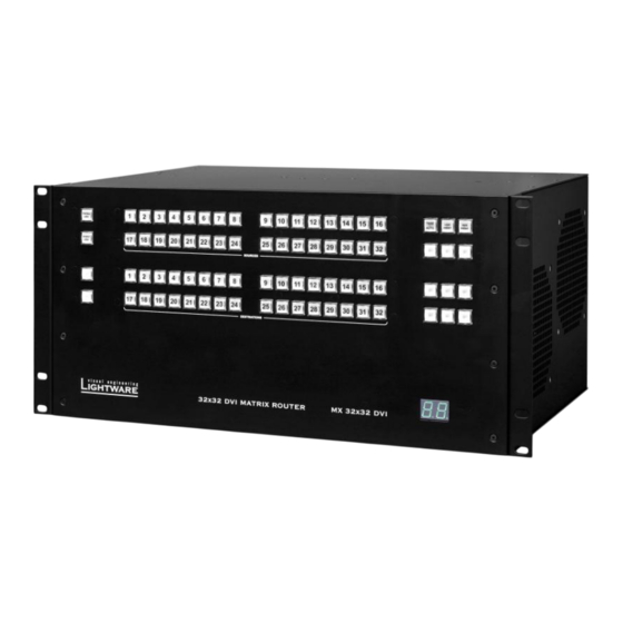
MX32x32DVI-Pro User’s Manual 1.4 Front and rear view 1.4.1 Front Panel view CONTROL LOCK Sources 1 to 32 Take/ Load Save Autotake Preset Preset OUTPUT LOCK Destinations 1 to 32 Status display Control Lock Disables or enables front panel operation. When red illuminated, operations on front panel are prohibited. -
Page 12: Rear View
1.4.2 Rear view CPU Card Reset GPIO DC voltage RS232 Ethernet CPU Live button switch contact closure indicators port port AC Power AC Input Cards Input Signal Detect Output Cards Card activity connector Fuse 1..4 LED-s 1..4 CPU card The main control unit of the device Reset button Hardware reset button. -
Page 13: Electrical Connections
User’s Manual 1.5 Electrical connections 1.5.1 DVI inputs MX32x32DVI-Pro provides 24 pole „digital only” DVI-D connectors for input connections. Always use high quality DVI cable for connecting sources and displays. Each input has a built in signal detection circuit with an LED located next to the input connector. -
Page 14: Dvi Outputs
Fiber Cable powering As special feature MX32x32DVI-Pro on DDC +5V output (pin 14 on output connectors) is able to supply 500 mA current to power fiber optical DVI cables. Standard DVI outputs or VGA cards supply only 55 mA current on +5V output, thus unable to power directly a fiber optical cable. -
Page 15: Rs 232/422 Control Port
User’s Manual 1.5.3 RS 232/422 control port Lightware MX32x32DVI-Pro can be remote controlled through industry standard 9 pole sub-D female connector located on the rear panel of the unit. The router can be ordered with RS232 or RS422 control port. -
Page 16: Advanced Edid Management
1.6 Advanced EDID Management MX32x32DVI-Pro provides an EDID Management feature with advanced functions that helps system integration. The built in EDID Router stores and emulates 100 EDID data plus all monitor's EDID that are connected to the output connectors. First 50 EDID are factory presets, while memories 50 to 100 are user programmable. -
Page 17: Operation
2.1 POWER Connect the power cord to the router’s IEC standard power input connector. MX32x32DVI-Pro is immediately powered ON when the power cord is connected to the AC source. The router does not have a power switch, it remains powered on, until AC line voltage is present. -
Page 18: Switching
2.2.3 SWITCHING Creating a connection or multiple connections in TAKE mode First press and release the selected source button. The pressed source button and all destination buttons which are currently connected to this source will light up. The dark remaining destination buttons are not connected to this source. -
Page 19: Save Or Load Presets
MX32x32DVI-Pro User’s Manual 2.2.4 SAVE or LOAD PRESETS The unit has 32 user programmable presets. Each preset stores a configuration regarding all input connections for all outputs. All presets are stored in a non volatile memory, the router keeps presets even in case of power down. Memory numbers are assigned to source buttons 1 to 32 (MX32X32) or to 16 (MX16*16). -
Page 20: Output Lock
2.2.6 OUTPUT LOCK Using Lightware routers there is a possibility to lock a destination. This feature prevents an accidental switching to the locked destination in case of important signal. Locking a destination means, that no input selection or muting can be done on that particular destination. - Page 21 MX32x32DVI-Pro User’s Manual Output Lock in AUTOTAKE mode Press and release the required destination button. Now the selected destination button and the currently configured source button light up (view mode) Press and release the Output Lock button. Now the Output Lock button lights up in red colour, and lock function is activated.
-
Page 22: Rs 232 / 422 Control
RS 232 / 422 control MX32x32DVI-Pro can be ordered with either RS232 or RS422 communication port. The port settings are done in the factory. D-sub connector pin assignments can be found on chapter 1. Changing and viewing protocols MX32x32DVI-Pro is equipped with multiple router protocols. -
Page 23: Switching And Control Commands
MX32x32DVI-Pro User’s Manual 3.1 Switching and control commands 3.1.1 Switch one input to one output Description: Switch input ii to output oo. Command {ii@oo} Response (Ooo●Iii)CrLf → Example: Connect input 1 to output 5. {1@5} ← (O05 I01)CrLf 3.1.2 Switch one input to all outputs Description: Switch input ii to all outputs. -
Page 24: View Mutes On All Outputs
Example 1: View connection on all outputs (MX32x32) (MX16x16) → → {VC} {VC} ← ← (ALL 01 02 03 04 05 06 07 08 (ALL 01 02 03 04 05 06 07 08 09 10 11 12 13 14 15 16 09 10 11 12 13 14 15 16 )CrLf 17 18 19 20 21 22 23 24 25 26 27 28 29 30 31 32 )CrLf... -
Page 25: Mute Specified Output
MX32x32DVI-Pro User’s Manual Example: (MX32x32) (MX16x16) → → {VM} {VM} ← ← (MUT 1 0 0 1 0 0 0 0 (MUT 1 0 0 1 0 0 0 0 0 0 0 0 0 0 0 0 0 0 0 0 0 0 0 0 )CrLf... -
Page 26: Save Preset To The Specified Memory Location
3.1.10 Save preset to the specified memory location Command {$zz} Response (SPRzz)CrLf Description:Save current ties to preset zz. Example:Save current connections to preset memory 7. → {$07} ← (SPR07)CrLf Info: The router saves the mute state of the outputs as well. Info: Lock states are not saved. -
Page 27: Router Status Commands
MX32x32DVI-Pro User’s Manual 3.2 Router Status commands 3.2.1 View product type Command Response (PRODUCT_TYPE)CrLf Description: Number of Number of Device DEVICE_NAME format: inputs Outputs type Example 1: The connected router is a → ← 32x32 frame (MX32X32DVI FRAME)CrLf Example 2: The connected router is a →... -
Page 28: View Router's Health
3.2.4 View Router’s health Desription: Command {st} Response "(STAT 3.3V 5V 12V temp rpm1 rpm2)"(CrLf) Legend: 3.3V System voltage EDID voltage FAN voltage System Temp.in C temp rpm1 FAN1 speed rpm2 FAN2 speed 3.2.5 View Installed i/o cards’ hardware Description: Shows the hardware name and revision of the installed cards’ Command {is} Response... -
Page 29: View Installed Controllers' Firmware
MX32x32DVI-Pro User’s Manual Preliminary: Naming conventions for future cards: MX-RJ45-DVI-IB SCH_1.0 PCB_1.0 Single link DVI-D input card with RJ-45 connector MX-RJ45-DVI-OB SCH_1.0 PCB_1.0 Single link DVI-D input card with RJ-45 connector MX-OPT-DVI-IB-NT SCH_1.0 PCB_1.0 Single link DVI-D input card with optical connector MX-OPT-DVI-OB-NT SCH_1.0... -
Page 30: Edid Router Commands
3.3 EDID router commands 3.3.1 Route EDID to the selected input (static) Description: Copies EDID from Command {ii:LLL} location LLL to input ii. LLL Response (E_SW_OK)CrLf (E_S_C) CrLf should be 1..100 Example: → {5:10} ← (E_SW_OK)CrLf ← (E_S_C) CrLf 3.3.2 Route EDID to the selected input (dynamic) Description: Copies EDID from Command {ii:LLL}... -
Page 31: View Edid Validity Table
MX32x32DVI-Pro User’s Manual 3.3.5 View EDID validity table Description: Shows EDID validity Command {wv} table, which contains information Response (EV VALIDITY_TABLE)CrLf about the EDID states. Example: (MX32x32) (MX16x16) → → {wv} {wv} ← ← 1111111111111111 1111111111111111 1111111111111111 1111111111111111 1111111111111110 1111111111111110... -
Page 32: Upload Edid Content From The Router
Example: Show the emulated EDID on DVI input#1 (for more information see session EDID Management: using EDID Router) (MX32x32) (MX16x16) → → {wh133} {wh117} ← ← (EH#133 NEC (EH#117 NEC 1600X1200@60 1600X1200@60 LCD2170NX)CrLf LCD2170NX)CrLf Legend: EDID manufacturer: Detailed timing block: 1600X1200@60 display device’s name: 60 LCD2170NX... -
Page 33: Download Edid Content To The Router
MX32x32DVI-Pro User’s Manual 3.3.8 Download EDID content to the router Description: EDID hex bytes can be written directly to the user programmable memory locations (locations #51...#100). Sequence: Prepares the router to accept EDID bytes to the specified location LLL {WL#LLL} ... -
Page 34: Router Initiated Commands
3.4 Router Initiated commands 3.4.1 EDID status changed Description: This is sent after all Command Issued either after EDID swirch commands which changes the or after connecting a new EDID (EDID copy, EDID switch), display device or after a new EDID source ie. a Response (E_S_C) CrLf new display device is connected... -
Page 35: Error Responses
MX32x32DVI-Pro User’s Manual 3.4.2 Error responses Invalid input number Description: Given input number exceeds the Response (ERR01)CrLf maximum number of inputs or equals zero. Invalid output number* Description: Given output number exceeds the Response (ERR02)CrLf installed number of outputs or equals zero. -
Page 36: Commands - Quick Summary
3.5 Commands – Quick summary DVI signal control commands See in Command description Command chapter DVI /Switch one input to one output 3.1.1 {ii@oo} DVI / Switch one input to all outputsSwitch one input to all 3.1.2 {ii@O} outputs DVI / View connection on the specified output 3.1.3 {?oo} ... -
Page 37: Ethernet Setup
MX32x32DVI-Pro User’s Manual Ethernet setup The matrix switchers can be controlled via ethernet identically the same way as via serial port. The same commands can be issued on the ethernet as on the serial port. The Ethernet settings can be accessed through Ethernet connection Step 1. - Page 38 Select “Use the following IP configuration”. Enter your settings (the Step 2. default is shown), then press OK to proceed. Step 3. You can access the router on port:10001 by default, but you can modify this number to any port except the followings: Restricted port numbers: 1-1024, 9999, 14000-14009, 30704, 30718 Info:...
- Page 39 If you are using the above setup, you can connect to the router two ways: Controller Connect to the router 192.168.254.254:10001 Lightware matrix controller application Launch the application, it will automatically find all routers on the same subnet, and enumerates it under “Comm port” menu...
-
Page 40: Software Control -Using Lightware Matrix Controller
Software control –Using Lightware Matrix Controller The unit can be controlled using Lightware Matrix Controller from a PC computer or Laptop through RS 232 or Ethernet port. 5.1 INSTALLING MATRIX CONTROLLER Info If older version of control software is installed please uninstall it before installing a newer version (see section 7.) - Page 41 After finishing the installation of Lightware Matrix Controller the following message appears: Step 7. To run Lightware matrix control software find and click from Start menu->Programs->Lightware->LW_matrix_controller_vXXX.jar from the desktop ikon (if this option was selected) via shortcut: To uninstall the control software double click on: Start menu ->Programs- >Lightware->...
-
Page 42: Using Lightware Matrix Controller
After starting the Lightware Matrix Controller, it automatically searches for Lightware devices connected to the LAN. If finds any, it picks its IP address and puts into the Comm Port menu. If there is not any matrix switchers connected to the PC, only comm ports will be shown in this menu. - Page 43 MX32x32DVI-Pro User’s Manual When the Lightware Matrix Controller finds the hardware, it defines the product type, and a button matrix area appears according to the input and output numbers of the router.I1; I2; I3...columns represents the inputs, the O1; O2; O3...rows the outputs.
-
Page 44: Menu Description
5.3 MENU Description Matrix Controller contains the following menus and submenus: LW Matrix Controller File -Synchronize matrix -Add new IP address -Create log file -Exit View -Edid router -Terminal window -Status window Comm Port -Serial ports -IP addresses Help 5.3.1 File menu File menu contains 3 items: Synchronize matrix Selecting Synchronize matrix will re-read connection information from the router... -
Page 45: View Menu
MX32x32DVI-Pro User’s Manual 5.3.2 View menu Edid router window This item is gray and can not be selected if the connected device does not have EDID ROUTER installed. For more information see Section: EDID operation Terminal window This is a general purpose serial terminal mainly for test and debug purposes. After a successful connection to a router this terminal can be used either via serial or TCP/IP connection. -
Page 46: Comm Port Menu
Serial ports available on the current PC IP addresses found on the network The IP addresses displayed in this window are those Lightware products, that are connected to the network. More than one units can be connected to one Local Area... -
Page 47: I/Oswitching
MX32x32DVI-Pro User’s Manual 5.4 I/O switching I1; I2; I3...columns represents the inputs, the O1; O2; O3...rows the outputs. Each red bulb represents a live connection. For making a connection click on the desired empty bulb. Mute outputs Outputs an be easily muted by clicking the button titled ’M’ beside the output. This means that no signal is present at this output. -
Page 48: Preset Operations
5.5 PRESET operations Preset operations can be done via the right panel named PRESET. Each Lightware matrix switcher has 32 preset memories, that can be loaded and saved any time. Front panel Preset operations effect only the first 8 preset memories, all others from 9 to 32 are available only via Matrix Controller software. -
Page 49: Error Messages
MX32x32DVI-Pro User’s Manual 5.6 ERROR Messages During remote operation there may happen some trouble with the communication. This case the Matrix Controller software displays error messages on the screen. Error messages are listed below: Unable to open Socket to the Server!!! Trigger: More than one user tries to access the router via LAN. -
Page 50: Web Control - Using Lightware Web Manager
Web control – Using Lightware Web Manager The main page of the Web Manager: Compatible web browsers: Microsoft Internet Explorer 6.0 or later versions Mozilla Firefox version 1.5 or later versions (recommended) Page 50 / 79... -
Page 51: Menu Description
With the Refresh button the user can update the temperature, voltage and fan values. Configuration This page shows the current network configuration of the matrix, such as IP settings and port number. Support The contact information to Lightware Visual Engineering is shown in this page. Page 51 / 79... -
Page 52: Crosspoint Operations
6.2 Crosspoint Operations 6.2.1 I/O switching Click on Control menu Select Set and View Crosspoints I1; I2; I3... columns represent the inputs, the O1; O2; O3... rows represent the outputs Each green square represents a live connection. For making a connection click on the desired grey square. 6.2.2 Mute outputs Outputs can be easily muted by clicking the button titled 'M' beside the output. -
Page 53: Lock Outputs
6.3 Preset operations Preset operations can be done in the right panel of the Control->Set and View Crosspoints page. Each Lightware matrix switcher has 32 preset memories, that can be loaded and saved any time. Front panel Preset operations effect only the first 8 preset memories, all others from 9 to 32 are available only via Matrix Controller software and Web Manager. -
Page 54: Save Preset
6.3.1 Save Preset Step 1 Make te desired configuration on matrix switching area. Step 2 Select preset memory location (Preset1...Preset32) where you want to save your configuration to. Step 3 Press Save Preset button. Now a message box appears that the preset is stored. 6.3.2 Load Preset Step 1 Select... -
Page 55: Change Emulated Edid At One Or All Inputs
MX32x32DVI-Pro User’s Manual 6.4.1 Change emulated EDID at one or all inputs All EDIDs are enumerated in the EDID list window. Step 1 Select the desired EDID from this list with a left mouse click, a popup menu appears. Step 2 Right click the Switch this EDID to item. -
Page 56: Learn Edid From Attached Display Device
6.4.2 Learn EDID from attached display device The matrix switcher can learn the EDID from the connected display device and store it in one of the user programmable memories. All the monitor's EDIDs are listed in the EDID list window, and also in the Last Attached Monitors EDIDs window. -
Page 57: Network Configuration
MX32x32DVI-Pro User’s Manual 6.5 Network Configuration The unit's network values display when you select Configuration->Network Settings. The following sections describe the configurable parameters on the Network Settings page. Info: It is possible to reload factory default IP setup from the front panel. To reload press CONTROL_LOCK button, press and hold OUTPUT_LOCK button and press LOAD PRESET button. -
Page 58: Static Ip Address Configuration
When you are finished, click Apply Settings button Info: To continue using the Web Manager, you must type in the IP address to the browser. 6.5.2 Static IP address configuration The user can manually assign an IP address to the unit, and enter related network settings. -
Page 59: Tcp Port Configuration
MX32x32DVI-Pro User’s Manual 6.5.4 TCP Port Configuration The user can configure the TCP port number, which is used to communicate with the matrix router through LAN. The input box initially contains the current setting. Step 1 Type the desired TCP port number into the input box Step 2 Press the Apply Settings button. -
Page 60: Advanced Edid Management: Using Edid Router
Only those resolutions and refresh rates are allowed, which are defined in EDID data. To provide proper EDID data for DVI sources MX32x32DVI-Pro has an Advanced EDID Manager, that can manage the emulated EDID on its all inputs indpendently. -
Page 61: About Advanced Edid Management
The first 50 EDID (1…50 inclusive) are factory preprogrammed and cannot be Info modified. These are the most commonly used resolutions. Info MX32x32DVI-PRO and MX16x16DVI-Pro can handle both 128 Byte EDID and 256 Byte extended EDID structures. The attached monitor’s EDID is stored automatically, until a new monitor is Info attached to that particular output. -
Page 62: Edid Router Menu Description
EDID menu contains 1 section: Syncronize EDID Selecting Synchronize EDID menu the Lightware Matrix Controller (PC) software rereads all EDID information from the connected MATRIX SWITCHER. During normal operation it is not necessary to use this menu item because the MATRIX SWITCHER always automatically reports every status change. -
Page 63: Edid Router Operation
MX32x32DVI-Pro User’s Manual 7.4 EDID Router operation Select View->EDID router window Info After a successful connection all identifying information is shown under the Help menu. The EDID ROUTER window appears and the software starts to synchronize EDID list with the Matrix switcher. -
Page 64: Change Emulated Edid At One Or All Inputs
7.4.1 Change emulated EDID at one or all inputs All EDID are enumerated in the switch EDID list. If you want to modify the current emulated resolution you can select one from this list. There is static EDID emulation or dynamic EDID emulation. Static EDID emulation means, when an EDID from memories 01..100 is selected and emulated at input(s) Dynamic EDID emulation occurs, when an attached monitor’s EDID is... -
Page 65: Learn Edid From Attached Display Device
MX32x32DVI-Pro User’s Manual 7.4.2 Learn EDID from attached display device The MATRIX SWITCHER can learn the EDID from the connected display device and store it in one of user programmable memory. All EDID is enumerated in the „Learn monitor EDID at output” list according to the router’s outputs. -
Page 66: Download Edid From File To Memory
7.4.3 Download EDID from file to memory The MATRIX SWITCHER is able to learn and store EDID from attached PC computer. EDID is stored in *.dat files. Step 1. Select File-> Download EDID from file to memory. Step 2. In the pop-up window browse your hard drive to find EDID file. The software checks if the selected file is a valid EDID file, than continue with step 3. -
Page 67: Firmware Upgrade
User’s Manual Firmware upgrade Using Lightware bootloader application to upgrade router’s firmware The matrix router can only be updated via LAN, so connect the matrix router to the local subnet. The router is DHCP enabled so it will get an IP address automatically, or if you do not have DHCP server, it will get an AUTO IP address from the AUTO IP domain. - Page 68 Select the controller(s) that need(s) new firmware by clicking the checkbox next to it. An open file dialog will pop up if you click on the last cell of the appropriate row. Now you can browse for the new firmware file to upload. After opening the new file, the new firmware field will contain the name of the firmware file.
- Page 69 MX32x32DVI-Pro User’s Manual Click “UPDATE SELECTED FIRMWARES” button. The router is being reprogrammed after clicking on ”YES” button, with the firmware you selected. If you select a file that doesn’t fit for the selected controller, you will get an information message about which file is wrong.
- Page 70 When the firmware upgrade is done, you will get the following window: When all upgrades are done, you can close the connection with the last device, by closing the application, or you can select another matrix router to upgrade. After closing the bootloader application, switch the upgraded devices off and then on.
-
Page 71: Specifications
MX32x32DVI-Pro User’s Manual Specifications Inputs (MX-DVID-IB) DVI input signals ............8x DVI single link / input board Connectors ..............24 pole DVI-D digital only Auto equalization: ............Yes, max 40dB at 825 MHz Input cable equalization: ........50 meter 24AWG cable at 1.65 Gbps EDID ...............Yes for each input connector... - Page 72 Enclosure ....................... Metal Enclosure dimensions ......176.5 mm H x 446 mm W x 302 mm D Weight NET ....................11.5 kg MX32x32DVI-Pro Rack mount ..................Yes, 5U high Enclosure ....................... Metal Enclosure dimensions ........221 mm H x 446 mm W x 302 mm D Weight NET ....................
-
Page 73: Mechanical Drawings
MX32x32DVI-Pro User’s Manual 9.1 Mechanical Drawings 9.1.1 Mechanical Drawings – Front View 482 mm Front view MX16x16DVI-Pro 482 mm Front view MX32x32DVI-Pro Page 73 / 79... -
Page 74: Mechanical Drawings - Rear View
9.1.2 Mechanical Drawings – Rear View 446 mm Rear view MX16x16DVI-Pro 176.5 mm 446 mm Rear view MX32x32DVI-Pro 221 mm Page 74 / 79... -
Page 75: Mechanical Drawings - Top View
MX32x32DVI-Pro User’s Manual 9.1.3 Mechanical Drawings – Top View 482 mm 302 mm 312 mm housing only including buttons and connectors 446 mm Top view MX16x16DVI-Pro and MX32x32DVI-Pro Page 75 / 79... -
Page 76: Mechanical Drawings - Left View
9.1.4 Mechanical Drawings – Left View air inlet: never block the air flow !!! Left view MX32x32DVI-Pro air inlet: never block the air flow !!! Left view MX16x16DVI-Pro Page 76 / 79... -
Page 77: Mechanical Drawings - Right View
MX32x32DVI-Pro User’s Manual 9.1.5 Mechanical Drawings – Right View fans (air outlet) : never block the air flow !!! Right view MX32x32DVI-Pro fans (air outlet) : never block the air flow !!! Right view MX16x16DVI-Pro Page 77 / 79... -
Page 78: Warranty
Lightware Visual Engineering warrants this product against defects in materials and workmanship for a period of three years from the date of purchase. The customer shall pay shipping charges when unit is returned for repair. Lightware will cover shipping charges for return shipments to customers. -
Page 79: Quality Check Record
MX32x32DVI-Pro User’s Manual Quality Check Record Model name Serial number Date of manufacture Checked 11.1 Hardware Card Card EDID MGMT Control P #1 Control P #2 Mother BRD OUT1 OUT2 SUBNET OUT3 MAC ADDR OUT4 IP ADDR 11.2 Electrical check...
Need help?
Do you have a question about the MX32x32DVI-Pro and is the answer not in the manual?
Questions and answers