Sign In
Upload
Download
Table of Contents
Contents
Add to my manuals
Delete from my manuals
Share
URL of this page:
HTML Link:
Bookmark this page
Add
Manual will be automatically added to "My Manuals"
Print this page
×
Bookmark added
×
Added to my manuals
Manuals
Brands
Lightware Manuals
Switch
UCX-2x1-HC30
User manual
Lightware UCX-2x1-HC30 User Manual
Hide thumbs
1
2
3
Table Of Contents
4
5
6
7
8
9
10
11
12
13
14
15
16
17
18
19
20
21
22
23
24
25
26
27
28
29
30
31
32
33
34
35
36
37
38
39
40
41
42
43
44
45
46
47
48
49
50
51
52
53
54
55
56
57
58
59
60
61
62
63
64
65
66
67
68
69
70
71
72
73
74
75
76
77
78
79
80
81
82
83
84
85
86
87
88
89
90
91
92
93
94
95
96
97
98
99
100
101
102
103
104
105
106
107
108
109
110
111
112
113
114
115
116
117
118
119
120
121
122
123
124
125
126
127
128
129
130
131
132
133
134
135
136
137
138
139
140
141
142
143
144
145
146
147
148
149
150
151
152
153
154
155
156
157
158
159
160
161
162
163
164
165
166
167
page
of
167
Go
/
167
Contents
Table of Contents
Troubleshooting
Bookmarks
Table of Contents
Table of Contents
Introduction
Description
Optional Accessories
Box Contents
Features of the Device
Model Comparison
Typical Application
Product Overview
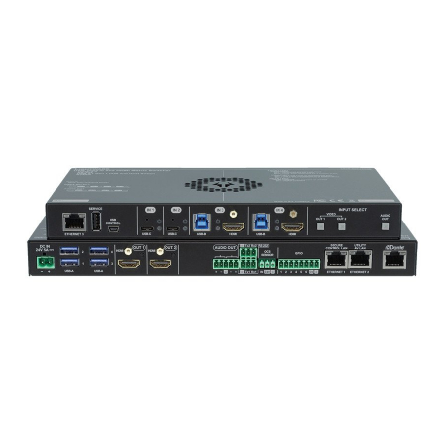
Front View
Rear View
Front Panel Control
Reset to Factory Default Settings
Button Functionality
Enable DHCP IP Address
Video Source Selection
Control Lock
Status Leds
Front Panel Leds
Rear Panel Leds
Ethernet Status Leds
Dante ® Audio out (in UCX-4X2-HC30D Model)
Installation
Mounting the Device (with Optionally Available Accessories)
High Rack Shelf
Mounting Options
Ventillation
Electrical Connections
HDMI Input and Output Ports
USB Connectors
Analog Stereo Audio
Secure Control LAN, Utility AV LAN, Configurable Ethernet Port
OCS Connector
GPIO - General Purpose Input/Output Ports
Power Delivery over Type-C
Powering Options
Connector
Power Data Objects (USB-C)
USB-C Cable Recommendation
Connecting Steps
Device Concept
Universal Switcher Concept
USB Interface
USB-C Interface
USB Data - USB 3.1 Gen1 Interface
USB Service Ports - USB 2.0 Interface
Video Interface
Displayport Alternate Mode
The Autoselect Feature
Displayport Alternate Mode and USB 3.X Mixed
Analog Audio Interface
Audio Interface
Dante ® Audio Interface
Ethernet Interface
Basic Network Security
Disable Ethernet Ports
Http/Https
Encryption (HTTPS, WSS)
Websocket Service (WS, WSS)
Serial Interface
Serial Port Diagram
Device Cloning - Configuration Backup and Restore
GPIO Interface
Further Built-In Features
OCS Interface
Software Control - Lightware Device Controller
Install and Update
Running the LDC
Establishing the Connection
LDC Layout
Video & Audio Crosspoint
Port Tiles
Port Properties Window
Welcomescreen
USB-C Inputs
HDMI Video Input
HDMI Video Output
Embedded Audio Input
Analog Audio Output
Framedetector
USB Crosspoint
USB-C Port Properties
USB-B Port Properties
EDID Menu
EDID Operations
EDID Summary Window
Editing an EDID
Ethernet
Creating an EDID - Easy EDID Creator
Control Menu
Gpio
OCS - Occupancy Sensor
Settings Menu
Status
Network
System
Advanced View Window
Lightware Rest Api Reference
Web Browser Plugins
Overview
Instructions for the Terminal Application Usage
Terminal Application
Protocol Rules
Command Structure Example
General Rules
Legend for the Control Commands
Lightware REST API Vs. LW3 Protocol
Method Types
Supported Commands
REST API Security
Encryption (HTTPS)
Authentication
Polling
Status Codes, Error Messages
Not Supported Commands
System Commands
Set the Device Label
Reset the Device
Restore the Factory Default Settings
Querying the Firmware Package Version
Control Lock
Set Current Time
Identifying the Device
Toggling the Dark Mode Setting
Setting the Delay of the Dark Mode
Lock the Video Port
Mute the Video Port
Video Port Settings - General
Switch an Input to All Outputs
Switch Video Input
Set the Autoselect Policy
Change the Autoselect-Included Input Ports
Change the Input Port Priority
Query the Connected Source
Query the Connected Destinations
Query the Input Switching Capability
Query the Video Signal Presence
HDCP Setting (Input Port)
Hdcpmode
Turn on Output 5V
Query Embedded Audio Presence
Set Output Signal Type
Mute Embedded Audio
Welcome Screen Settings
Display Welcome Screen Image
Display Welcome Screen Text
Set Welcome Screen Text
Reset Welcome Screen Image
Query the Connected Source
Query the Connected Destinations
Video Port Settings - USB-C Related Commands
Switch Audio Input
Audio Port Settings
Restart Link Training
Set the Followed Video Port to Autoselect
Lock the Audio Port
Mute the Audio Port 1
Set Autoselect Operation Mode
Analog Audio Output Volume (Db) Setting
Analog Audio Output Volume Percent Setting
Query the Audio Signal Presence
Mute the Audio Port 2
Analog Audio Output Level Settings by Steps (Db)
Analog Audio Output Level Settings by Steps in Percent
Analog Audio Output Balance by Steps
Setting the Balance
USB Port Settings
Switch USB Input
Query the Connected Source
Query the Connected Destinations
Lock the USB Port
Set the Followed Video Port to Autoselect
Change the Autoselect Included USB Ports
Set the USB Autoselect Policy
Setting the 5V Sending to the USB Peripherals
Change the USB Port Priority
USB Port Settings - USB-C Related Commands
Set USB-C Power
Set Displayport Alternate Mode Policy
Query the Host Alternate Mode Support
Query the Status of the Alternate Mode
Query the Port Data Role
Query the Port Power Role
Query the Preferred Resolution of a User EDID
Query the Validity of a Dynamic EDID
Query the Emulated Edids
EDID Management
Set Port Power Role
Emulating an EDID to an Input Port
Emulating an EDID to All Input Ports
Copy an EDID to User Memory
Deleting an EDID from User Memory
Resetting the Emulated Edids
Ethernet Port Configuration
Set the DHCP State
Change the IP Address (Static)
Setting the Hostname
Change the Gateway Address (Static)
Apply Network Settings
Change the Subnet Mask (Static)
Network Security
Query Network Service Port Number
Enable/Disable Network Service Port
Query the Username for Authentication
Enable/Disable Ethernet Port
Set Password for Authentication
Enable Authentication
Query Data Bits
Parity Setting
BAUD Rate Setting
Serial Port Configuration
Stop Bits Setting
Query the Serial over IP Port Number
Enable the Serial over IP Port
Serial Port Messaging
Sending a Message Via RS-232
Setting the Output Level for a Specified Time
Toggling the Level of a GPIO Pin
Setting the Output Level of a GPIO Pin
Setting the Direction of a GPIO Pin
GPIO Port Configuration
OCS Port Configuration
Querying the Input Level of an OCS Pin
Set the Sensor Type
Querying the Reported OCS State
Lightware REST API Quick Summary
Lw3 Programmers' Reference
Overview
Instructions for the Terminal Application Usage
Instructions for the Websocket (WS) or Secured Websocket (WSS) Usage
Legend for the Control Commands
LW3 Tree Structure and Command Structure (Examples)
General Rules
Protocol Rules
Command Types
Prefix Summary
Error Messages
Escaping
Signature
Subscription
Notifications about the Changes of the Properties
Querying the Firmware Package Version
Control Lock
Set Current Time
Restore the Factory Default Settings
Reset the Device
Set the Device Label
System Commands
Identifying the Device
Toggling the Dark Mode Setting
Setting the Delay of the Dark Mode Setting
Video Port Settings - General
Switch Video Input
Switch an Input to All Outputs
Change the Autoselect Included Input Ports
Set the Autoselect Policy
Mute the Video Port
Lock the Video Port
Change the Input Port Priority
Query the Connected Source
Query the Connected Destinations
Query the Input Switching Capability
Query the Video Signal Presence
HDCP Setting (Input Port)
Hdcpmode
Embeddedaudiopresent
Embeddedaudiomute
Set Welcome Screen Text
Display Welcome Screen Text
Welcome Screen Settings
Display Welcome Screen Image
Output5Vmode
Outputsignaltype
Reset Welcome Screen Image
Video Port Settings - USB-C Related Commands
Restart Link Training
Audio Port Settings
Switch Audio Input
Query the Connected Source
Mute the Audio Port 1
Lock the Audio Port
Set the Followed Video Port to Autoselect
Set Autoselect Operation Mode
Query the Connected Destinations
Mute the Audio Port 2
Query the Audio Signal Presence
Analog Audio Output Volume (Db) Setting
Analog Audio Output Volume Percent Setting
Setting the Balance
Analog Audio Output Level Settings by Steps (Db)
Analog Audio Output Level Settings by Steps in Percent
Analog Audio Output Balance by Steps
USB Port Settings
Switch USB Input
Query the Connected Source
Setting the 5V Sending to the USB Peripherals
Lock the USB Port
Query the Connected Destinations
Set the USB Autoselect Policy
Set the Followed Video Port to Autoselect
Advertisement
Quick Links
1
Reset to Factory Default Settings
Download this manual
User's Manual
UCX-2x1-HC30, UCX-2x2-H30
UCX-4x2-HC30, UCX-4x2-HC30D
Universal Switcher
v1.5
02-07-2021
Table of
Contents
Previous
Page
Next
Page
1
2
3
4
5
Advertisement
Table of Contents
Troubleshooting
TROUBLESHOOTING
145
How to Speed Up the Troubleshooting Process
147
Need help?
Do you have a question about the UCX-2x1-HC30 and is the answer not in the manual?
Ask a question
Questions and answers
Related Manuals for Lightware UCX-2x1-HC30
Switch Lightware UCX Series User Manual
(109 pages)
Lightware UCX-4x2-HC30, UCX-4x2-HC30D - Switcher Quick Start Guide
(article)
Switch Lightware UMX-HDMI-140 User Manual
Universal multimedia switcher (87 pages)
Switch Lightware UMX-HDMI-140 Quick Start Manual
(2 pages)
Switch Lightware UMX-HDMI-140 Quick Start Manual
(2 pages)
Switch Lightware UMX-HDMI-140 User Manual
Universal multimedia switcher (93 pages)
Switch Lightware UMX-HDMI-140 Series User Manual
Universal multimedia switcher (126 pages)
Switch Lightware UMX-HDMI-140 Series User Manual
Universal multimedia switcher (161 pages)
Switch Lightware UMX4x4-Pro2 Quick Start Manual
(2 pages)
Switch Lightware UCX-2x2-H30 User Manual
(167 pages)
Switch Lightware MX32x32DVI-Pro User Manual
(79 pages)
Switch Lightware MX Quick Start Manual
Mx4x4dvi, 4x4dvi-dl, 6x6dvi-dl, 8x8dvi-dl, mx8x4dvi-pro, 8x8dvi-pro, 8x8dvi-hdcp-pro, 8x8hdmi-pro, mx9x9dvi-slim, 12x12dvi-slim, 16x16dvi-slim, mx9x9dvi-plus, 12x12dvi-plus, 16x16dvi-plus (2 pages)
Switch Lightware MMX8x8-HDMI-4K-A User Manual
Multiport matrix switcher (112 pages)
Switch Lightware MX2-8X8-HDMI20-AUDIO User Manual
Multimedia matrix switcher (74 pages)
Switch Lightware MMX4x2-HT200 User Manual
Standalone multimedia matrix switcher mmx4x2 series (98 pages)
This manual is also suitable for:
Ucx-2x2-h30
Ucx-4x2-hc30
Ucx-4x2-hc30d
Table of Contents
Save PDF
Print
Rename the bookmark
Delete bookmark?
Delete from my manuals?
Login
Sign In
OR
Sign in with Facebook
Sign in with Google
Upload manual
Upload from disk
Upload from URL


Need help?
Do you have a question about the UCX-2x1-HC30 and is the answer not in the manual?
Questions and answers