Lightware UMX-HDMI-140 Series User Manual
Universal multimedia switcher
Hide thumbs
Also See for UMX-HDMI-140 Series:
- User manual (126 pages) ,
- Quick start manual (2 pages) ,
- Quick start manual (2 pages)

Related Manuals for Lightware UMX-HDMI-140 Series


Summary of Contents for Lightware UMX-HDMI-140 Series
- Page 1 User’s Manual User’s Manual UMX-HDMI-140 UMX-HDMI-140-Plus Universal Multimedia Switcher v3.1 11-05-2021 ...
- Page 2 UMX-HDMI-140 series– User's Manual Important Safety Instructions Waste Electrical & Electronic Equipment Common Safety Symbols WEEE Class II apparatus construction. Symbol Description This marking shown on the product or its literature, The equipment should be operated only from the power source indicates that it should not be disposed with other indicated on the product.
- Page 3 #dhcp This keyword is placed at the DHCP (dynamic IP address) setting in the front panel operation, the Lightware Device Controller (LDC) and the LW3 programmer's reference section. See the list of all hashtag keywords of the document in the...
-
Page 4: Table Of Contents
4.14. Software Control Modes ............32 5.11.3. Front Panel ..................62 3.1.1. 1U High Rack Shelf ................19 5.11.4. Backup ................... 62 5. SOFTWARE CONTROL - LIGHTWARE DEVICE CONTROLLER ..33 3.1.2. Under-desk Double Mounting Kit ............ 19 5.11.5. System ................... 62 3.2. Electrical Connections ..............19 5.1. Install and Update ..............34 5.12. The Built-in Miniweb ..............63... - Page 5 UMX-HDMI-140 series– User's Manual Table of Contents 6.3.3. Control Protocol Query ..............70 7.2. Instructions for the Terminal Application Usage ....83 7.6.13. Unlock an Input Port..............92 6.3.4. Firmware Version Query ..............70 7.3. Protocol Rules ................83 7.6.14. Mute Output ................... 92 6.3.5. Connection Test................
- Page 6 UMX-HDMI-140 series– User's Manual Table of Contents 7.9.6. Querying the Condition Trigger Counter ........102 7.15.8. Querying the Last Recognized Message (Hex) ......112 7.22.1. Setting the Direction of a GPIO Pin ..........121 7.9.7. Testing an Action ................102 7.15.9. Clearing the Last Recognized Stored Message ......
- Page 7 UMX-HDMI-140 series– User's Manual 10.1.2. Advanced EDID Management ............. 145 10.2. HDCP Management ..............146 10.2.1. Protected and Unprotected Content .......... 146 10.2.2. Disable Unnecessary Encryption ..........146 10.3. Pixel Accurate Reclocking .............147 11. APPENDIX ..................148 11.1. Specification ................149 11.2. Content of Backup File ............151 11.3. Input/Output Port Numbering ..........152...
-
Page 8: Introduction
1. Introduction UMX-HDMI-140 series– User's Manual I ntroduction Thank you for choosing Lightware’s UMX-HDMI-140 series switcher family. In the first chapter we would like to introduce the device highlighting the most important features in the below listed sections: Description Î... -
Page 9: Description
About the Serial Number DisplayPort input Lightware devices contain a label indicating the unique serial number of the product. The structure is the DVI-I input following: Analog Stereo Audio Ports 3.5 mm Jack input 7A000941 ... -
Page 10: Features
Batch of Commands A batch of LW3 commands (salvo) can be run by the Lightware device either by a previously Dark Mode stored macro or by sending a file to the device with the desired commands. -
Page 11: Typical Applications
Electrical Connections section. UMX-HDMI-140 transmits HDMI audio/video signal toward the sink devices. The Lightware HDMI-4K De-embedder de-embeds the audio signal and transmits it to the Active speakers. The De-embedder does not need local powering because it can be supplied via the HDMI cable by the source and the cable extensions... - Page 12 VC. The Switcher can be controlled easily via LAN network using our controller software (LDC); see the details in the Software Control - Lightware Device Controller chapter. The HDMI cable between the Switcher and the codec can be up to 20 meters thanks to the built-in...
- Page 13 The Collaboration Room is built with a ceiling mounted projector and a projection screen. The output of UMX-HDMI-140 is connected to the projector by HDMI cable which can be extended up to 40 meters using a Lightware HDMI-Extender device. The HDMI-Extender does not need local powering because it can be supplied via the HDMI cable.
-
Page 14: Product Overview
2. Product Overview UMX-HDMI-140 series– User's Manual P roduct Overview The following sections are about the physical structure of the device, input/ output ports and connectors: Front View Î Rear View Î Status LEDs Î Front Panel Operation - AV Functions Î... -
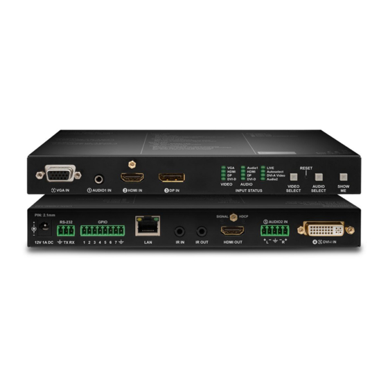
Page 15: Front View
Locking RJ-45 connector for configuring the device using Lightware Device Video Select Button for switching between video sources. Controller (LDC), or updating it using Lightware Device Updater (LDU). Any third- button party control system can use this port to control the device. -
Page 16: Status Leds
2. Product Overview UMX-HDMI-140 series– User's Manual 2.3. Status LEDs 2.4. Front Panel Operation - AV Functions 2.4.1. Video Select Button Input status LEDs (VIDEO, AUDIO) The video source is not selected. blinking The video source is selected but signal is not detected. -
Page 17: Front Panel Operation - Special Functions
Press the Audio Select and Show Me buttons together (within 100 ms) to disable/enable front panel buttons; This feature is to help finding the desired device in the Device discovery window of Lightware Device front panel LEDs blink 3 times when locking/unlocking. If the control lock is enabled and a button is pressed, Controller software. -
Page 18: Installation
3. Installation UMX-HDMI-140 series– User's Manual I nstallation The chapter is about the installation of the device and connecting to other appliances, presenting also the mounting options and further assembly steps: Mounting Options Î Electrical Connections Î... -
Page 19: Mounting Options
The UD-kit double makes it easy to mount a single switcher on any flat surface (e.g. furniture). To mount the switcher Lightware supplies optional accessories for different usage. There are two kinds of mounting kits with similar fixing method. The switcher has two mounting holes with inner thread on the bottom side;... -
Page 20: Vga Connector
3. Installation UMX-HDMI-140 series– User's Manual 3.2.2. VGA Connector 3.2.4. HDMI Connector The switcher provides a standard 15-pole D-SUB female connector for connecting The extender provides standard 19 pole HDMI connector for output. Always use high quality VGA devices. Always use high-quality VGA cable for connecting sources and displays;... -
Page 21: Ethernet Connector (Lan Port)
Wiring of CATx Cables plug. The pin assignments are the following for the detector and the emitter: Lightware recommends the termination of LAN cables on the basis of TIA/EIA T 568 A or TIA/ EIA T 568 B standards. Detector – 3-pole-TRS Emitter –... -
Page 22: Connecting Steps
3. Installation UMX-HDMI-140 series– User's Manual 3.3. Connecting Steps Connect the switcher and the sources using the inputs and VGA / DVI-I / HDMI / DisplayPort cables. HDMI Audio Optionally connect an audio device (e.g. the VGA laptop) to the audio input port. -
Page 23: Device Concept
4. Device Concept UMX-HDMI-140 series– User's Manual D evice Concept The following chapter describes the features of the device with few real-life examples. The topics that are described: Universal Switcher Concept Î Port Diagram Î Video Interface Î... -
Page 24: Universal Switcher Concept
UMX-HDMI-140 series– User's Manual 4.1. Universal Switcher Concept The following figure describes the port diagram of the UMX-HDMI-140 series switcher: UMX-HDMI-140 is a universal audio/video switcher with analog/digital conversion and audio embedding functions. The device receives analog (VGA, DVI-A) and digital (DP, HDMI, DVI-D) video signals and transmits HDMI. -
Page 25: Audio Interface
4. Device Concept UMX-HDMI-140 series– User's Manual 4.4. Audio Interface 4.4.2. Audio Options - Example 4.4.1. Audio Input Modes The device can receive embedded digital audio signal on the HDMI, DisplayPort, and DVI-D input ports and analog audio signal on the Jack and the Phoenix input ports. -
Page 26: The Autoselect Feature
DVI-D IN Laptop VGA IN Port with Port with priority priority 2 has a Priorities can be set in Lightware Device Controller software, see related settings in the Video Output section. 2 is selected valid signal? Port with Port with priority... -
Page 27: Serial Interface
4. Device Concept UMX-HDMI-140 series– User's Manual 4.6. Serial Interface 4.6.2. RS-232 Modes 4.6.1. Serial Interface Control Mode The incoming data from the given port is processed and interpreted by the CPU. The mode allows to control Technical Background the receiver directly. -
Page 28: Recognizer
First, configure the recognizer for the serial communication, after that, set the events in the Event Manager (for more details see the Event Manager section). The RS-232 recognizer settings has to be done with Lightware Device Controller Software (see the Message Recognizer... -
Page 29: Tcp Recognizer
This feature allows the LW device to be controlled over HTTP. In this case, a batch of commands is sent over HTTP to the Lightware device for processing. Save the LW3 commands into a file, post it to the DIFFERENCE: This feature is available only for UMX-HDMI-140-Plus from FW package v1.3.0b5. -
Page 30: Gpio Interface
You can establish connection between the controller/ the IR IN connectors. To order IR receiver and transmitter units please contact sales@lightware.com. controllable device and the switcher by the 8-pole Phoenix connector. Seven pin's direction is configurable Technical Background independently based on needs of the application. -
Page 31: The Event Manager Feature
DIFFERENCE: This feature is available only for UMX-HDMI-140-Plus from FW package v1.3.0b5. . according to the pre-defined settings. Lightware Device Controller contains a user-friendly software tool and allows to create Events by defining a Condition and an Action. This improvement in the Event Manager works as if a condition is detected. When a complex control system is built, a Condition may trigger numerous Actions. -
Page 32: Further Built-In Features
User has more possibilities to control the device besides the front panel buttons. The following list contains the software control modes: Lightware Device Controller (LDC) - you can connect to the device via our control software using Ethernet ▪ or RS-232 interface and control or configure the device as you wish. For the details see the... -
Page 33: Software Control - Lightware Device Controller
S oftware Control - Lightware Device Controller The device can be controlled by a computer through the Ethernet and RS-232 port using Lightware Device Controller (LDC). The software can be installed on a Windows PC or macOS. The application and the User’s manual can be downloaded from www.lightware.com. -
Page 34: Install And Update
The Device Discovery window appears automatically and the program checks the available updates on Format: LightwareDeviceController -z <magnifying_value> Lightware’s website and opens the update window if the LDC found updates. Example: LightwareDeviceController -z 1.2 The current and the update version number can be seen at the top of the window and they are shown in this ATTENTION! The last set value is stored and applied when LDC is started without a parameter. -
Page 35: Establishing The Connection
Step 1. Connect the device to a computer via USB, RS-232 or Ethernet. as you can expand the list of Favorite devices with any Lightware device that is connected via Ethernet by any Step 2. Run the controller software; device discovery window appears automatically. There are three tabs for of the following ways: the different type of interfaces;... -
Page 36: Serial Tab
5. Software Control - Lightware Device Controller UMX-HDMI-140 series– User's Manual 5.3.3. Further Tools Highlighting the Device DIFFERENCE: This feature is available only from FW package v1.3.0b5. The Tools menu contains the following options: Log Viewer: The tool can be used for reviewing log files which have been saved previously. -
Page 37: Crosspoint Menu
5. Software Control - Lightware Device Controller UMX-HDMI-140 series– User's Manual 5.4. Crosspoint Menu When LDC finds the hardware, it determines the product type, and the LDC starts with the default page, showing the Crosspoint menu. #crosspoint #switch Main menu The available menu items are displayed. -
Page 38: Port Properties Windows
5. Software Control - Lightware Device Controller UMX-HDMI-140 series– User's Manual 5.5. Port Properties Windows Port Tiles The colors of the port tiles and the displayed icons represent different states and information: Clicking on the port tile opens the Port properties window. This section shows the available settings and status information by port types. -
Page 39: Digital Video Inputs
5. Software Control - Lightware Device Controller UMX-HDMI-140 series– User's Manual 5.5.2. Digital Video Inputs Available settings: ▪ Mute/unmute the port; Clicking on the HDMI, DisplayPort, or DVI-D input port icon results opening the Port properties window. The ▪... -
Page 40: Analog Audio Inputs
5. Software Control - Lightware Device Controller UMX-HDMI-140 series– User's Manual 5.5.3. Analog Audio Inputs 5.5.4. Digital Audio Inputs Port properties window of the AUDIO2 (Phoenix) input Port properties window of the HDMI audio input Certain parameters of the analog audio input signal can be set as follows:... -
Page 41: Video Output
5. Software Control - Lightware Device Controller UMX-HDMI-140 series– User's Manual 5.5.5. Video Output Available settings: ▪ Mute/unmute the port; Click on the output port to display its properties. The most important information and settings are available ▪... -
Page 42: Audio Output
#diagnostic framedetector Frame detector window Lightware’s Frame Detector function works like a signal analyzer and makes possible to determine the exact Port properties window of the HDMI audio output video format that is present on the port, thus helps to identify many problems. E.g. actual timing parameters may differ from the expected and this may cause some displays to drop the picture. -
Page 43: Test Pattern
5. Software Control - Lightware Device Controller UMX-HDMI-140 series– User's Manual 5.6.2. Test Pattern Test Pattern Configuration on Testpattern Port (I6) The port generates an image which can be displayed when there is no incoming signal on the port. Each port... -
Page 44: Cec (On Hdmi Ports)
Sending CEC Commands section. Both the layout and functionality are similar to the design of a remote control. Layout of CEC panel in Lightware Device Contoller ATTENTION! Make sure that the controlled unit is CEC-capable and this function is enabled. -
Page 45: Edid Menu
5. Software Control - Lightware Device Controller UMX-HDMI-140 series– User's Manual 5.8. EDID Menu 5.8.1. EDID Operations Advanced EDID Management can be accessed by selecting the EDID menu. There are two panels: left one Changing Emulated EDID contains Source EDIDs, right one contains Destination places where the EDIDs can be emulated or copied. -
Page 46: Edid Summary Window
The software resolves the raw EDID and displays it as readable information to the user. All descriptors can be edited, and saved in an EDID file, or uploaded to the User memory. For more details about EDID Editor please visit our website (https://lightware.com/support/guides-and-white-papers) and download EDID Editor user's manual. -
Page 47: Creating An Edid - Easy Edid Creator
Since above mentioned Advanced EDID Editor needs more complex knowledge about EDID, 5.9.1. RS-232 Lightware introduced a wizard-like interface for fast and easy EDID creation. With Easy EDID Creator it is possible to create custom EDIDs in four simple steps. By clicking on the Create button below Source panel, Easy EDID Creator is opened in a new window. -
Page 48: Message Recognizer
5. Software Control - Lightware Device Controller UMX-HDMI-140 series– User's Manual 5.9.2. Message Recognizer INFO: The stored content is the incoming data which arrives before the delimiter or between the two delimiters. DIFFERENCE: This feature is available only in UMX-HDMI-140- Plus model. -
Page 49: Gpio
5. Software Control - Lightware Device Controller UMX-HDMI-140 series– User's Manual 5.9.3. GPIO 5.9.4. Ethernet GPIO tab in the Control menu Ethernet tab in the Control menu The GPIO port has 7 pins, which operate at TTL digital signal levels and can be controlled by LDC or protocol Two ports are displayed in the Ethernet settings: Local and CPU. - Page 50 This feature is available only in UMX-HDMI-140-Plus model from FW package v1.3.0b5. ATTENTION! This feature means posting or putting HTTP messages from the Lightware device to another This tab is for the preparation and monitoring interface for the TCP recognizer which may trigger Event device.
- Page 51 This feature means sending HTTP messages from an external device to the Lightware device. Encrypted transmission (HTTPS) is not supported. In this case, a batch of commands can be sent over HTTP to the Lightware device for processing. Post the commands to the <IP_address>/protocol.lw3 address and the commands are processed immediately and sequentially.
-
Page 52: Infra
5. Software Control - Lightware Device Controller UMX-HDMI-140 series– User's Manual 5.9.5. Infra Description Function ATTENTION! The device has no built-in Infrared receiver and transmitter. For the complete usage attach Code number. an IR emitter unit to the IR OUT and an IR detector unit to the IR IN connectors. - Page 53 5. Software Control - Lightware Device Controller UMX-HDMI-140 series– User's Manual Ports Tab in UMX-HDMI-140-Plus Sending pronto hex codes (Little-endian format) Copy the raw, little endian-format IR code into the Send Pronto Hex entry field and click the Send button.
-
Page 54: Macros
5. Software Control - Lightware Device Controller UMX-HDMI-140 series– User's Manual 5.9.6. Macros DIFFERENCE: This feature is available only in UMX-HDMI-140-Plus model from FW package v1.3.0b5. DEFINITION: Macro is a batch of pre-defined commands stored in the device. -
Page 55: Variables
5. Software Control - Lightware Device Controller UMX-HDMI-140 series– User's Manual 5.9.7. Variables Value Section You can set the value of the variable by the field. The type of the variable is determined automatically based DIFFERENCE: This feature is available only in UMX-HDMI-140-Plus model from FW package v1.3.0b5. - Page 56 5. Software Control - Lightware Device Controller UMX-HDMI-140 series– User's Manual Scan and Store This tool can be used to get the value (or a part) of an LW3 property. The defined path will be checked according to the pattern and the result will be saved into the variable (number or string type).
-
Page 57: Event Manager
HDCP active) are necessary to display but it is not easy when the device is hard to access (e.g. built under the desk). For more details and examples about Event Manager please visit our website (https://lightware.com/support/guides-and-white-papers) and download Event Manager user's guide in the Downloads section. -
Page 58: Create Or Modify An Event
5. Software Control - Lightware Device Controller UMX-HDMI-140 series– User's Manual 5.10.2. Create or Modify an Event The Link Tool The new interface allows creating more actions for the Wizard Mode same condition. In that case, a condition can trigger The wizard mode lists the most common conditions more actions. -
Page 59: Special Tools And Accessories
5. Software Control - Lightware Device Controller UMX-HDMI-140 series– User's Manual Linking a Macro (Action) Delay the Action no delay Condition = true Perform the action DIFFERENCE: This feature is available only In most cases the Action is... -
Page 60: Clear One Or More Event(S)
5. Software Control - Lightware Device Controller UMX-HDMI-140 series– User's Manual Condition Triggering The Concept DIFFERENCE: This feature The UMX-HDMI-140-Plus switcher is connected to a projector by the HDMI output port. The switcher is also available only in UMX-HDMI-140-Plus connected to the projector by the RS-232 port and can send commands via the serial line. -
Page 61: Settings Menu
Cleartext Login (Login Settings) section. There are TCP/IP ports in Lightware devices which are not protected by the login, so you can disable them if necessary. For example, due to the working method of the LW2 communication, the Cleartext login does not provide protection when LW2 command is sent to the device, that is why the TCP port no.10001 shall be blocked manually. -
Page 62: Front Panel
▪ Controlling the device (Send option), or ▪ Querying parameters (Receive option) to/from the Lightware device. Do not forget to press the Apply changes button to store the new settings. ATTENTION! The first three lines are factory default values and they are necessary for the proper working. -
Page 63: The Built-In Miniweb
5. Software Control - Lightware Device Controller UMX-HDMI-140 series– User's Manual 5.12. The Built-in Miniweb 5.12.1. Opening the Miniweb The Miniweb is available by: DEFINITION: The miniweb is a dedicated location in the memory where an HTML file can be uploaded to. -
Page 64: Miniweb Customization
5. Software Control - Lightware Device Controller UMX-HDMI-140 series– User's Manual The Default Status Page Customized HTML If there is no control page uploaded, the default status page will be displayed (which is also available by The default control page can be replaced in the LDC;... -
Page 65: Backup (Configuration Cloning)
Installing multiple devices with the same customized configuration settings can be done in a few easy steps: Configuration cloning of Lightware LW3 devices is a simple method that eliminates the need to repeatedly configure certain devices to have identical (non-factory) settings. If the devices are installed in the same Step 1. -
Page 66: Upload The Settings To A Device (Restore)
5. Software Control - Lightware Device Controller UMX-HDMI-140 series– User's Manual 5.13.3. Upload the Settings to a Device (Restore) WARNING! Please note that the settings will be permanently overwritten with the restored parameters in the device. Withdrawal is not possible. -
Page 67: Advanced View Window
5. Software Control - Lightware Device Controller UMX-HDMI-140 series– User's Manual 5.14. Advanced View Window LW3 protocol help Pushing the button results a help window opening which describes the most important information about LW3 protocol commands in HTML format. -
Page 68: Lw2 Programmer's Reference
UMX-HDMI-140 series– User's Manual L W2 Programmer' s Reference The device can be controlled through a reduced command set of LW2 protocol commands to ensure the compatibility with other Lightware products. The supported LW2 commands are described in this chapter. Protocol Description Î... -
Page 69: Protocol Description
UMX-HDMI-140 series– User's Manual 6.1. Protocol Description 6.2. Instructions for the Terminal Application Usage The protocol description hereinafter stands for Lightware protocol. The below listed commands can be sent Terminal Application to the device in RAW format via the TCP/IP port no. 10001. -
Page 70: General Lw2 Commands
6. LW2 Programmer's Reference UMX-HDMI-140 series– User's Manual 6.3. General LW2 Commands 6.3.4. Firmware Version Query Command and Response #firmwareversion 6.3.1. List of All Available LW2 Commands ȩ {f} Command and Response Ȩ (FW:<firmware_version>)CrLf ȩ {lcmd} Example Ȩ (LCMD# LCMD: List all commands)CrLf ȩ... -
Page 71: Device Label Query
6. LW2 Programmer's Reference UMX-HDMI-140 series– User's Manual 6.3.8. Device Label Query 6.3.11. Restarting of the Device Command and Response #label #devicelabel The device can be restarted without unplugging power. #restart #reboot #reset ȩ {label} Command and Response Ȩ... -
Page 72: Crosspoint And Port Settings
6. LW2 Programmer's Reference UMX-HDMI-140 series– User's Manual 6.4. Crosspoint and Port Settings 6.4.2. Mute Output Command and Response #mute Port Numbering ȩ {#<out>·<layer>} Applicable media layers Port Port LW2 port number Ȩ (1MT<out>·<layer>)CrLf type Audio Video Audio + Video... -
Page 73: Lock Output
6. LW2 Programmer's Reference UMX-HDMI-140 series– User's Manual 6.4.4. Lock Output 6.4.6. View Connection State on the Output Lock an output port. The state of the output cannot be changed until unlocking. Command and Response #portstatus Command and Response #lock ȩ... -
Page 74: View Crosspoint Size
6. LW2 Programmer's Reference UMX-HDMI-140 series– User's Manual 6.4.7. View Crosspoint Size 6.4.8. Autoselect Mode Query Shows the physical crosspoint size. The autoselect mode of the audio or video outputs can be changed. Command and Response Command and Response #autoselect ȩ... -
Page 75: Autoselect - Input Priority Query
6. LW2 Programmer's Reference UMX-HDMI-140 series– User's Manual 6.4.10. Autoselect - Input Priority Query 6.5. Network Configuration The settings of audio or video autoselect input priority can be queried as follows. 6.5.1. IP Status Query Command and Response The network configuration of the device can be queried as follows. -
Page 76: Ip Address Query
6. LW2 Programmer's Reference UMX-HDMI-140 series– User's Manual 6.5.2. IP Address Query 6.5.4. Subnet Mask Query IP address can be queried as follows. IP address can be queried as follows. Command and Response Command and Response ȩ {IP_ADDRESS=?} ȩ... -
Page 77: Gateway Address Query
6. LW2 Programmer's Reference UMX-HDMI-140 series– User's Manual 6.5.6. Gateway Address Query 6.5.9. Apply Network Settings Gateway address can be queried as follows. Applying the network settings and restart the network interface. Command and Response ATTENTION! The command is always requires as the last step for applying the modified network settings. -
Page 78: Parameters Settings
6. LW2 Programmer's Reference UMX-HDMI-140 series– User's Manual 6.6.2. RS-232 Parameters Settings 6.6.3. RS-232 Control Protocol Port Setting The parameters of local RS -232 port can be set as follows. The control protocol of local RS -232 port can be set as follows. -
Page 79: Gpio Configuration
6. LW2 Programmer's Reference UMX-HDMI-140 series– User's Manual 6.7. GPIO Configuration 6.7.2. Setting of Level and Direction for Each Pins GPIO pins can be configured as follows. See more details about GPIO connector in the GPIO - General 6.7.1. Query the Level and Direction for Each Pins... -
Page 80: Lw2 Commands - Quick Summary
6. LW2 Programmer's Reference UMX-HDMI-140 series– User's Manual 6.8. LW2 Commands – Quick Summary General LW2 Commands Crosspoint and Port Settings List of All Available LW2 Commands Switch an Input to the Output ȩ {lcmd} ȩ {<in>@<out>•<layer>}... - Page 81 6. LW2 Programmer's Reference UMX-HDMI-140 series– User's Manual Network Configuration IP Status Query ȩ {IP_STAT=?} IP Address Query ȩ {IP_ADDRESS=?} IP Address Setting ȩ {IP_ADDRESS=<mode>;<ip_address>} Subnet Mask Query ȩ {IP_NETMASK=?} Subnet Mask Setting ȩ {IP_NETMASK=<subnet_mask>} Gateway Address Query ȩ...
-
Page 82: Lw3 Programmers' Reference
7. LW3 Programmers’ Reference UMX-HDMI-140 series– User's Manual L W3 Programmers’ Reference The device can be controlled through Lightware 3 (LW3) protocol commands to ensure the compatibility with other Lightware products. The supported LW3 commands are described in this chapter. Overview Î... -
Page 83: Overview
‘nodes’, ‘properties’ and ‘methods’. The VIDEO Advanced View of the Lightware Device Controller software is the perfect tool for browsing and learning how XP the LW3 protocol can be used in practice. -
Page 84: Command Types
7. LW3 Programmers’ Reference UMX-HDMI-140 series– User's Manual 7.3.3. Command Types 7.3.4. Prefix Summary DEFINITION: The prefix is a 2-character long code that describes the type of the response. GET command The following prefixes are defined in the LW3 protocol: The GET command can be used to get the child nodes, properties and methods of a specific node. -
Page 85: Signature
7. LW3 Programmers’ Reference UMX-HDMI-140 series– User's Manual 7.3.7. Signature 7.3.9. Notifications about the Changes of the Properties DEFINITION: The signature is a four-digit-long hexadecimal value that can be optionally placed before When the value of a property is changed and the user is subscribed to the node, which the property belongs every command to keep a command and the corresponding responses together as a group. -
Page 86: System Commands
7. LW3 Programmers’ Reference UMX-HDMI-140 series– User's Manual 7.4. System Commands 7.4.4. Query the Firmware Version Command and Response #firmwareversion 7.4.1. Query the Product Name ç GET·/SYS/MB.FirmwareVersion The name of the product is a read-only parameter and cannot be modified. -
Page 87: Lock The Front Panel Buttons
7. LW3 Programmers’ Reference UMX-HDMI-140 series– User's Manual 7.4.8. Lock the Front Panel Buttons 7.4.10. Identify the Device Calling the method results the blinking of the status LEDs for 10 seconds. The feature helps to identify the Command and Response #controllock #buttonlock #lockbutton device itself in the rack shelf. -
Page 88: Running A Macro
7. LW3 Programmers’ Reference UMX-HDMI-140 series– User's Manual 7.4.13. Running a Macro 7.5.2. Login the Device DIFFERENCE: This feature is available only in UMX-HDMI-140-Plus model fromFW package v1.3.0b5. Command and Response DEFINITION: Macro is a batch of pre-defined commands stored in the device. -
Page 89: Video Port Settings
7. LW3 Programmers’ Reference UMX-HDMI-140 series– User's Manual 7.6. Video Port Settings The Most Common Received Port Status Responses INFO: Video port numbering can be found in the Input/Output Port Numbering section. 7.6.1. Query the Status of Source Ports... -
Page 90: Query The Status Of Destination Port
7. LW3 Programmers’ Reference UMX-HDMI-140 series– User's Manual 7.6.2. Query the Status of Destination Port 7.6.5. Query the Video Autoselect Settings Command and Response #portstatus Command and Response #autoselect ç GET·/MEDIA/VIDEO/XP.DestinationPortStatus ç GET·/MEDIA/VIDEO/XP.DestinationPortAutoselect pr·/MEDIA/VIDEO/XP.DestinationPortStatus=<out1_state>;<out2_state>;<…>;<out#_state> pr·/MEDIA/VIDEO/XP.DestinationPortAutoselect=<out1_set>;<out2_set>;<…>;<out#_set> æ æ The response contains 5 ASCII characters for each port. The first character indicates the mute/lock state, The response shows the settings of each output one by one. -
Page 91: Query The Input Port Priority
7. LW3 Programmers’ Reference UMX-HDMI-140 series– User's Manual 7.6.7. Query the Input Port Priority 7.6.9. Mute an Input Port Command and Response Command and Response #mute ç GET·/MEDIA/VIDEO/XP.PortPriorityList ç CALL·/MEDIA/VIDEO/XP:muteSource(<in>) æ pr·/MEDIA/VIDEO/XP.PortPrioirtyList= <out1_list>;<out2_list>;<…>;<out#_list> æ mO·/MEDIA/VIDEO/XP:muteSource The response shows the priority of each output one after another. The priority number can be from 0 to 31;... -
Page 92: Lock An Input Port
7. LW3 Programmers’ Reference UMX-HDMI-140 series– User's Manual 7.6.12. Lock an Input Port 7.6.16. Lock Output Command and Response #lock Command and Response #lock ç CALL·/MEDIA/VIDEO/XP:lockSource(<in>) ç CALL·/MEDIA/VIDEO/XP:lockDestination(<out>) æ mO·/MEDIA/VIDEO/XP:lockSource æ mO·/MEDIA/VIDEO/XP:lockDestination Example Example ç CALL /MEDIA/VIDEO/XP:lockSource(I1) ç CALL /MEDIA/VIDEO/XP:lockDestination(O1) æ... -
Page 93: Hdcp Setting (Output Port)
7. LW3 Programmers’ Reference UMX-HDMI-140 series– User's Manual 7.6.19. HDCP Setting (Output Port) 7.6.21. Test Pattern Resolution HDCP capability can be set to Auto/Always on the output ports, thus, non-encrypted content can be Command and Response transmitted to a non-HDCP compliant display. See more information in the HDCP Management section. -
Page 94: Hdmi Mode Settings (Output Port)
7. LW3 Programmers’ Reference UMX-HDMI-140 series– User's Manual 7.6.23. HDMI Mode Settings (Output Port) Command and Response #signaltype SET·/MEDIA/VIDEO/<out>.HdmiModeSetting=<mode> ç pw·/MEDIA/VIDEO/<out>.HdmiModeSetting=<mode> æ Parameters Parameter Parameter description Value Parameter value Auto <mode> HDMI mode HDMI 24bit HDMI 30bit... -
Page 95: Audio Port Settings
7. LW3 Programmers’ Reference UMX-HDMI-140 series– User's Manual 7.7. Audio Port Settings The Most Common Received Port Status Responses INFO: Audio port numbering can be found in the Input/Output Port Numbering section. 7.7.1. Query the Status of Source Port... -
Page 96: Query The Status Of Destination Port
7. LW3 Programmers’ Reference UMX-HDMI-140 series– User's Manual 7.7.2. Query the Status of Destination Port 7.7.5. Query the Audio Autoselect Settings Command and Response #portstatus Command and Response #autoselect ç GET·/MEDIA/AUDIO/XP.DestinationPortStatus ç GET·/MEDIA/AUDIO/XP.DestinationPortAutoselect pr·/MEDIA/AUDIO/XP.DestinationPortStatus=<out_status> pr·/MEDIA/AUDIO/XP.DestinationPortAutoselect=<out_set> æ æ The response contains 5 ASCII characters for each port. The first character indicates the mute/lock state, The response shows the settings of each output one by one. -
Page 97: Query The Input Port Priority
7. LW3 Programmers’ Reference UMX-HDMI-140 series– User's Manual 7.7.7. Query the Input Port Priority 7.7.9. Mute Audio Input Command and Response Command and Response #mute ç GET·/MEDIA/AUDIO/XP.PortPriorityList ç CALL·/MEDIA/AUDIO/XP:muteSource(<in>) pr·/MEDIA/AUDIO/XP.PortPrioirtyList=<in1_prio> æ mO·/MEDIA/AUDIO/XP:muteSource æ Legend Example <out_prio>: The input port priority order of the given output port: I1 to I5. -
Page 98: Mute Audio Output
7. LW3 Programmers’ Reference UMX-HDMI-140 series– User's Manual 7.7.13. Mute Audio Output 7.7.17. Analog Audio Input Volume Command and Response #mute Command and Response ç CALL·/MEDIA/AUDIO/XP:muteDestination(<out>) SET·/MEDIA/AUDIO/<in>.Volume=<level> ç æ mO·/MEDIA/AUDIO/XP:muteDestination pw·/MEDIA/AUDIO/<in>.Volume=<level> æ Example Parameters ç CALL /MEDIA/AUDIO/XP:muteDestination(O1) <level>... -
Page 99: Event Manager Basics
7. LW3 Programmers’ Reference UMX-HDMI-140 series– User's Manual 7.8. Event Manager Basics 7.8.2. Setting a Condition by Linking Another Condition Command and Response The graphical interface of the Event Manager can be found in the LDC which allows creating any kind of Events. -
Page 100: Setting An Action By Specifying A Direct Path
7. LW3 Programmers’ Reference UMX-HDMI-140 series– User's Manual 7.8.4. Setting an Action by Specifying a Direct Path 7.9. Event Manager Tool Kit Command and Response 7.9.1. Setting the Delay SET·/EVENTS/E<loc>.Action=<expression> ç In most cases, the Action is performed immediately after the Condition is detected. But sometimes a delay pw·/EVENTS/E<loc>.Action=<expression>... -
Page 101: Setting The Name Of The Event
7. LW3 Programmers’ Reference UMX-HDMI-140 series– User's Manual 7.9.3. Enable the Event Example 1 (simple delay) ç SET /EVENTS/E1.ConditionTimeout=10 Command and Response æ pw /EVENTS/E1.ConditionTimeout=10 SET·/EVENTS/E<loc>.Enabled=<true/false> ç If the Condition is detected (the ConditionDetect property becomes true), the ConditionTimeoutPending property pw·/EVENTS/E<loc>.Enabled=<true/false>... -
Page 102: Querying The Condition Trigger Counter
7. LW3 Programmers’ Reference UMX-HDMI-140 series– User's Manual 7.9.6. Querying the Condition Trigger Counter 7.10. Variable-Management DIFFERENCE: This command is available only in UMX-HDMI-140-Plus model from FW package v1.3.0b5. DIFFERENCE: This feature and the commands are available only in UMX-HDMI-140-Plus model from FW package v1.3.0b5. -
Page 103: Addition And Subtraction (Cycle Method)
7. LW3 Programmers’ Reference UMX-HDMI-140 series– User's Manual 7.10.3. Addition and Subtraction (Cycle Method) Examples Change messages (CHG) can be seen after each response for the better understanding, which is not the part The value of a numeric variable can be increased by adding a positive value or it can be decreased by adding... -
Page 104: Value Change With Intervals (Case)
7. LW3 Programmers’ Reference UMX-HDMI-140 series– User's Manual 7.10.4. Value Change with Intervals (Case) 7.10.5. Scan and Store This command can be used to change the value of a variable if it fits in any of the defined intervals. -
Page 105: Reformatting A Value
7. LW3 Programmers’ Reference UMX-HDMI-140 series– User's Manual 7.11. Ethernet Port Configuration Further Examples <path>.<property> Property Value <pattern> Scanned result 7.11.1. Set the DHCP State /MANAGEMENT/STATUS.CpuTemperature 42 C; 0;75; 0;7 ATTENTION! When you change a network property the new value is stored but the applySettings method /MANAGEMENT/STATUS.CpuFirmware... -
Page 106: Change The Subnet Mask (Static)
æ pw /MANAGEMENT/MACFILTER.FilterEnable=true New MAC address is saved into the 4th property with name 'Tech', which may query/set parameters from/in the Lightware device. The FilterEnable property is set to true, thus, the filter is enabled. Applied firmware package: v1.3.0b5 | LDC software: v2.5.6b2... -
Page 107: Lw2 Control Port Blocking
7. LW3 Programmers’ Reference UMX-HDMI-140 series– User's Manual 7.12.2. LW2 Control Port Blocking 7.12.5. Powering on a Computer over Ethernet (Wake-on-LAN) DIFFERENCE: This command is available only for UMX-HDMI-140-Plus from FW package v1.3.0b5. DIFFERENCE: This command is available only from FW package v1.3.0b5. -
Page 108: Ethernet Message Sending
7. LW3 Programmers’ Reference UMX-HDMI-140 series– User's Manual 7.13. Ethernet Message Sending 7.13.3. Sending a TCP Binary Message (HEX-format) The command is for sending a binary message in Hexadecimal format. This method does not require escaping The device can be used for sending a message to a certain IP:port address. The three different commands the control and non-printable characters. -
Page 109: Sending A Udp Text (Ascii-Format)
The features and commands below available only for UMX-HDMI-140-Plus from FW escaping or inserting control characters. package v1.3.0b5. Command and Response Http post and put messages can be sent from the Lightware device for more integration with third-party devices. #http #new ç... -
Page 110: Setting The Message Header
ç SET /CTRL/HTTP/C1.Header=Host: 192.168.0.220\r\nContent-Type: text/xml\r\nAuthorization: Basic Preparation YWRtaW46TGlnaHR3YXJlMDE= Step 1. Set a TCP client in the Lightware device (three TCP clients can be run at the same time), set the æ pw /CTRL/HTTP/C1.Header=Host: 192.168.0.220\r\nContent-Type: text/xml\r\nAuthorization: Basic properties of the target TCP server. -
Page 111: Setting The Tcp/Ip Port Number Of The Tcp Server
7. LW3 Programmers’ Reference UMX-HDMI-140 series– User's Manual 7.15.2. Setting the TCP/IP Port Number of the TCP Server 7.15.6. Setting the Timeout Command and Response When the set time is elapsed after the last received message and delimiter was not detected, the device saves the data into the Rx, RxHex, Hash properties. -
Page 112: Querying The Last Recognized Message (Hex)
7. LW3 Programmers’ Reference UMX-HDMI-140 series– User's Manual 7.15.8. Querying the Last Recognized Message (Hex) 7.15.11. Querying the Last Recognized Active Message (Hex) The recognized message is stored as a hex message in the below property till the next recognized message Command and Response or until the clear() method is called. -
Page 113: Port Configuration
7. LW3 Programmers’ Reference UMX-HDMI-140 series– User's Manual 7.16. RS-232 Port Configuration 7.16.3. BAUD Rate Setting 7.16.1. Protocol Setting Command and Response SET·/MEDIA/UART/P1.Baudrate=<baud_rate> ç Command and Response #serial #rs232 #rs-232 #protocol pw·/MEDIA/UART/P1.Baudrate=<baud_rate> æ SET·/MEDIA/UART/P1.ControlProtocol=<protocol> ç Parameters pw·/MEDIA/UART/P1.ControlProtocol=<protocol> æ Parameter... -
Page 114: Stopbits Setting
7. LW3 Programmers’ Reference UMX-HDMI-140 series– User's Manual 7.16.5. Stopbits Setting 7.16.7. Command Injection Mode Command and Response Command and Response #commandinjection SET·/MEDIA/UART/P1.StopBits=<stopbits> SET·/MEDIA/UART/P1.CommandInjectionEnable=<logical_value> ç ç pw·/MEDIA/UART/P1.StopBits=<stopbits> pw·/MEDIA/UART/P1.CommandInjectionEnable=<logical_value> æ æ Parameters Parameters Parameter Parameter description Value Parameter value... -
Page 115: Message Sending
7. LW3 Programmers’ Reference UMX-HDMI-140 series– User's Manual 7.17. RS-232 Message Sending 7.17.4. Using Hexadecimal Codes Hexadecimal codes can be inserted in the ASCII message when using: 7.17.1. Sending a Message (ASCII-format) via RS-232 sendMessage command: CALL /MEDIA/UART/P1:sendMessage(C00\x0D) The command is for sending a command message in ASCII-format. This method allows escaping the control characters. -
Page 116: Message Recognizer
7. LW3 Programmers’ Reference UMX-HDMI-140 series– User's Manual 7.18. RS-232 Message Recognizer 7.18.2. Set the Delimiter Hex This property stores the delimiter that is between the messages (e.g. Cr, Lf, Space). The value has to be in DIFFERENCE: This feature is available only for UMX-HDMI-140-Plus from FW pack v1.2.0b12. -
Page 117: Querying The Last Recognized Message (String)
7. LW3 Programmers’ Reference UMX-HDMI-140 series– User's Manual 7.18.4. Querying the Last Recognized Message (String) 7.18.7. Querying the Last Recognized Active Message (String) The recognized message is stored as a string in the below property till the next recognized message or until The recognized data is stored in string in the below property temporary. -
Page 118: Set The Active Timeout
7. LW3 Programmers’ Reference UMX-HDMI-140 series– User's Manual 7.18.9. Set the Active Timeout 7.19. Sending CEC Commands This property is responsible for clearing the ActiveRx, ActiveRxHex, ActiveHash properties after the elapsed DIFFERENCE: This feature is available only for UMX-HDMI-140-Plus from FW package v1.3.0b5. -
Page 119: Further Commands
7. LW3 Programmers’ Reference UMX-HDMI-140 series– User's Manual 7.19.2. Further Commands 7.19.4. Sending CEC Commands in Hex Format Command and Response ç CALL·/MEDIA/CEC/<port>:sendHex(<hex_code>) æ mO·/MEDIA/CEC/<port>:sendHex ç CALL·/MEDIA/CEC/<port>:send(<command>) Parameters æ mO·/MEDIA/CEC/<port>:send Parameter Parameter description Values Value description Parameters <port>... -
Page 120: Infrared Port Configuration
7. LW3 Programmers’ Reference UMX-HDMI-140 series– User's Manual 7.20. Infrared Port Configuration 7.21. Infrared Message Sending INFO: Infrared input and output port numbering can be found in the Input/Output Port Numbering section. DIFFERENCE: This feature is available only in UMX-HDMI-140-Plus model. -
Page 121: Sending Pronto Hex Codes In Big-Endian Format Via Ir Port
Step 3. Remove all the non-hexadecimal characters (e.g. spaces, h characters etc.) from the code. The output level can be changed from high to low and low to high by the command below. The pronto hex code which learned by a Lightware device is big-endian format. Command and Response ç... -
Page 122: Edid Management
7. LW3 Programmers’ Reference UMX-HDMI-140 series– User's Manual 7.23. EDID Management 7.23.3. Query the Preferred Resolution of an User EDID Command and Response Parameters ç GET·/EDID/U/<user>.PreferredResolution Parameter Description pr·/EDID/U/<user>.PreferredResolution=<resolution> æ <emulated> The emulated EDID memory of the desired input port. Example: E1. -
Page 123: Deleting An Edid From User Memory
7. LW3 Programmers’ Reference UMX-HDMI-140 series– User's Manual 7.23.7. Deleting an EDID from User Memory Command and Response ç CALL·/EDID:delete(<user>) æ mO·/EDID:delete Example ç CALL /EDID:delete(U1;U2;U6) æ mO /EDID:delete 7.23.8. Resetting the Emulated EDIDs Command and Response ç CALL·/EDID:reset() æ... -
Page 124: Lw3 Commands - Quick Summary
7. LW3 Programmers’ Reference UMX-HDMI-140 series– User's Manual 7.24. LW3 Commands - Quick Summary System Commands Login the Device CALL·/LOGIN:login(<password>) Query the Product Name Logout from the Device GET·/.ProductName CALL·/LOGIN:logout(<password>) Set the Device Label Enable the Cleartext Login Function SET·/MANAGEMENT/UID/DeviceLabel=<custom_name>... - Page 125 7. LW3 Programmers’ Reference UMX-HDMI-140 series– User's Manual Unlock an Input Port Switching Audio Input CALL·/MEDIA/VIDEO/XP:unlockSource(<in>) CALL·/MEDIA/AUDIO/XP:switch(<in>:<out>) Mute Output Query the Audio Autoselect Settings CALL·/MEDIA/VIDEO/XP:muteDestination(<out>) GET·/MEDIA/AUDIO/XP.DestinationPortAutoselect Unmute Output Change the Autoselect Mode ...
- Page 126 7. LW3 Programmers’ Reference UMX-HDMI-140 series– User's Manual Event Manager Basics Variable-Management How to arrange an Event? Value Assignment SET·/EVENTS/E<loc>.Condition=<expression> SET·/CTRL/VARS/V<loc>.Value=<value> Setting a Condition by Linking Another Condition Addition and Subtraction (Add Method) SET·/EVENTS/E<loc>.Condition=<event_nr>...
- Page 127 7. LW3 Programmers’ Reference UMX-HDMI-140 series– User's Manual HTTP Post Receiving Blocking Sending a Put Message SET·/MANAGEMENT/SERVICEFILTER.HttpEnabled=<port_mode> CALL·/CTRL/HTTP/C1:put(<body_text>) Powering on a Computer over Ethernet (Wake-on-LAN) TCP Message Recognizer CALL·/MEDIA/ETHERNET:wakeOnLan(MAC_address) Setting the IP Address of the TCP Server Setting the Host Name SET·/CTRL/TCP/C<loc>.ServerIP=<IP_address>...
- Page 128 7. LW3 Programmers’ Reference UMX-HDMI-140 series– User's Manual RS-232 Port Configuration Querying the Last Recognized Message (String) GET·/MEDIA/UART/RECOGNIZER.Rx Protocol Setting Querying the Last Recognized Message(Hex) SET·/MEDIA/UART/P1.ControlProtocol=<protocol> GET·/MEDIA/UART/RECOGNIZER.RxHex RS-232 Operation Mode Clearing the Last Recognized Stored Message SET·/MEDIA/UART/P1.Rs232Mode=<mode>...
- Page 129 7. LW3 Programmers’ Reference UMX-HDMI-140 series– User's Manual Enable/Disable Output Signal Modulation SET·/MEDIA/IR/D1.EnableModulation=<modulation> Infrared Message Sending Sending Pronto Hex Codes in Little-endian Format via IR Port CALL·/MEDIA/IR/<out>:sendProntoHex(<hex_code>) Sending Pronto Hex Codes in Big-endian Format via IR Port ...
-
Page 130: Firmware Update
This chapter is meant to help customers perform firmware updates on our products by giving a few tips on how to start and by explaining the features of the Lightware Device Updater v2 (LDU2) software. To get the latest software and firmware pack can be downloaded from www.lightware.com. -
Page 131: Introduction
8.2. Preparation may exist for all users installed for all users Most Lightware devices can be controlled over more interfaces (e.g. Ethernet, USB, RS-232). But the firmware ATTENTION! Using the default Normal install is highly recommended. can be updated usually over one dedicated interface, which is the Ethernet in most cases. -
Page 132: Running The Software
When the software is started by the shortcut, the device discovery screen appears. You have two options: DISCOVER DEVICES Press the Search for devices button to start finding the Lightware devices: ▪ Starting the LDU2 by double-clicking on the shortcut/program file, or ▪... -
Page 133: The Updating Steps
In the case of factory reset, you can save the settings of the device in the Lightware Device Controller software and restore it later. The following flow chart demonstrates how this function works in the background. -
Page 134: Updating Via Gui
8. Firmware Update UMX-HDMI-140 series– User's Manual 8.4. Updating Via GUI The Meaning of the Symbols To update the desired device(s) via the Graphical User Interface follow these steps. Show The log about the updating process of the device ... -
Page 135: Command Line Interface (Cli)
Step 1. Open an Explorer window where the cmd file is located, the default is: c:\Program Files (x86)\Lightware\Lightware Device Updater V2\LightwareDeviceUpdaterV2_CLI.cmd. Step 2. Click on the address line (highlighed with blue in the picture), type cmd.exe and press enter. The command interpreter window of Windows is opened at the path of the LDU2 install folder. -
Page 136: How To Use
You only have to define the parameter if C:\Program Files (x86)\Lightware\Lightware Device Updater V2>LightwareDeviceUpdaterV2_CLI.cmd version you want to apply a different value. The order of the options is arbitrary. C:\Program Files (x86)\Lightware\Lightware Device Updater V2>lib\jre\bin\java.exe -jar lib\ldu2.jar version Important Notes LDU2 version: 2.9.0b9 Script API version: 1.3.9... -
Page 137: Device Info
192.168.1.7 --reportProgress Report update progress in percentage form. Default: false optional C:\Program Files (x86)\Lightware\Lightware Device Updater V2>lib\jre\bin\java.exe -jar lib\ldu2.jar deviceInfo --ip Certain LFP2 packages have features which can be applied 192.168.1.7 Package-specific options optional at this command; see the Package Options section. -
Page 138: Restore
--forceNoBackup: if true, no backup file will be created (default: false) --uploadDefaultMiniWeb: If true, the default built-in miniweb will be uploaded to the device. (default: c:\Program Files (x86)\Lightware\Lightware Device Updater V2>lib\jre\bin\java.exe -jar lib\ldu2.jar restore --ip false) 192.168.1.7 --backupFile C:\mybackup.lw3 --keepOriginalIp [2021-04-28 07:51:23.206] [ INFO] [... -
Page 139: Complex Examples
C:\Program Files (x86)\Lightware\Lightware Device Updater V2>LightwareDeviceUpdaterV2_CLI.cmd update --ip 192.168.1.7 --factoryDefault --package c:\Firmwares\UMX-HDMI-140_v1.3.0b5.lfp2 C:\Program Files (x86)\Lightware\Lightware Device Updater V2>LightwareDeviceUpdaterV2_CLI.cmd update --ip 192.168.1.7 --package c:\Firmwares\UMX-HDMI-140_v1.3.0b5.lfp2 --backupFolder c:\My_backup --clearTextLoginPw C:\Program Files (x86)\Lightware\Lightware Device Updater V2>lib\jre\bin\java.exe -jar lib\ldu2.jar update --ip qwer1234 192.168.1.7 --factoryDefault --package c:\Firmwares\UMX-HDMI-140_v1.3.0b5.lfp2 [2021-04-29 21:44:59.927] [ INFO] [ main] - Device IPs: [192.168.1.7]... -
Page 140: Exit Codes
If an update is not successful, the Export log button becomes red. If you press the button, you can The error line contains further information about the error. download the log file as a ZIP package which can be sent to Lightware Support if needed. The log files Querying the Exit Code under Windows ®... -
Page 141: Troubleshooting
9. Troubleshooting UMX-HDMI-140 series– User's Manual T roubleshooting Usually, if the system seems not to transport the signal as expected, the best strategy for troubleshooting is to check signal integrity through the whole signal chain starting from source side and moving forward to switcher end. -
Page 142: Use Case Studies
9. Troubleshooting UMX-HDMI-140 series– User's Manual 9.1. Use Case Studies Symptom Root cause Action Refer to At first, check front panel LEDs and take the necessary steps according to their states. For more information Audio signal about status, LEDs refer to... -
Page 143: How To Speed Up The Troubleshooting Process
In the case of Event Manager issue the event file and/or backup file from the Device Controller ▪ software. The more of the above information you can give us the better. Please send these information to the Lightware Support Team (support@lightware.com) to speed up the troubleshooting process. Applied firmware package: v1.3.0b5 | LDC software: v2.5.6b2... -
Page 144: Technologies
10. Technologies UMX-HDMI-140 series– User's Manual Technologies The following sections contain descriptions and useful technical information how the devices work in the background. The content is based on experiences and cases we met in the practice. These sections help to understand features... -
Page 145: Edid Management
(static EDID emulation), or from the last attached monitor’s memory (dynamic EDID emulation). For example, the Lightware device can be set up to emulate a sink device, which is connected to one of the outputs. In this case, the EDID automatically changes, if the monitor is replaced with another display device (as long as it has a valid EDID). -
Page 146: Hdcp Management
To avoid unnecessary HDCP encryption, Lightware introduced the HDCP enabling/disabling function: the Not HDCP-compliant Sink 2. HDCP capability can be disabled in the Lightware device. If HDCP is disabled, the connected source will The layout is the same as in the previous case: non-HDCP compliant display device is connected to the detect that the sink is not HDCP capable, and turn off authentication. -
Page 147: Pixel Accurate Reclocking
Without reclocking, sparkles, noise, and jaggies appear on the image. Lightware’s sophisticated Pixel Accurate Reclocking technology fixes more problems than general TMDS reclocking. It removes not only intra-pair skew but inter-pair skew as well. The Pixel Accurate Reclocking... -
Page 148: Appendix
11. Appendix UMX-HDMI-140 series– User's Manual Appendix Tables, drawings, guides, hashtag keyword list and technical details as follows: Specification Î Content of Backup File Î Input/Output Port Numbering Î Mechanical Drawings Î Cable Wiring Guide Î... -
Page 149: Specification
11. Appendix UMX-HDMI-140 series– User's Manual 11.1. Specification Max. resolution ......................Up to 1600x1200@60 Hz HDMI Input General HDMI port connector type ................19-pole HDMI Type A receptacle Compliance ..............................CE Standard ..........................DVI 1.0, HDMI 1.4 EMC compliance (emission) ....................IEC/EN 55032:2015 Color depth ................ - Page 150 11. Appendix UMX-HDMI-140 series– User's Manual Color depth ................Deep color support up to 36 bits, 12 bit/color 3D support ..............................Yes Color space ......................RGB, YCbCr 4:4:4, YcbCr 4:2:2 HDCP compliant............................Yes, 1.1 Supported resolutions at 8 bits/color * ..up to 4096x2048@30Hz (4:4:4) or 4096x2048@60Hz (4:2:0) * All standard VESA and CEA resolutions up to 300MHz (HDMI1.4) and other custom resolutions up to...
-
Page 151: Content Of Backup File
11. Appendix UMX-HDMI-140 series– User's Manual 11.2. Content of Backup File Available Stop bits ..........................1 / 1.5 / 2 Infrared The backup file contains numerous settings and parameters saved from the device. When the file is uploaded to a device, the followings will be overwritten: Number of IR ports ........................2 (1x RX, 1x TX) -
Page 152: Input/Output Port Numbering
11. Appendix UMX-HDMI-140 series– User's Manual 11.3. Input/Output Port Numbering Front View The following table contains the input and output ports with their ID numbers which shall be used in protocol Audio1 LIVE RESET commands. HDMI HDMI... -
Page 153: Cable Wiring Guide
11. Appendix UMX-HDMI-140 series– User's Manual 11.5. Cable Wiring Guide From Unbalanced Output to Balanced Input Inputs and outputs of audio devices are symmetric or asymmetric. The main advantage of the symmetric 2 x 6.3 (1/4") TS - Phoenix 2 x RCA - Phoenix 3.5 (1/8") TRS - Phoenix... -
Page 154: Factory Default Settings
11. Appendix UMX-HDMI-140 series– User's Manual 11.6. Factory Default Settings Parameter Setting/Value Databits Parameter Setting/Value Parity Crosspoint settings Stopbits Video I6 (Testpattern) Operation mode Event Manager / Control / Command Injection Audio I1 (Analog audio in 1) -
Page 155: Factory Edid List
11. Appendix UMX-HDMI-140 series– User's Manual 11.8. Factory EDID List Resolution Type EDID features Resolution Type EDID features Resolution Type EDID features 640 x 480p @ 60.00 Hz 1280 x 720p @ 50.00 Hz 2chLPCM 1280 x 768p @ 75.00 Hz 848 x 480p @ 60.00 Hz... -
Page 156: Applied Ports (Network Settings)
11. Appendix UMX-HDMI-140 series– User's Manual 11.9. Applied Ports (Network Settings) The following ports are necessary to pass via a network switch/firewall for a proper working between the Resolution Type EDID features device and the softwares: F103 1280 x 1024p @ 75.02 Hz... -
Page 157: Release Notes Of The Firmware Packages
▪ Added new method for CEC control button sendClick (Advanced Control pack v3) for UMX-HDMI-140- Plus only! ▪ Condition link was broken is fixed. ▪ Added LMDMP (Lightware Multicast Device Management Protocol) feature. ▪ Notification message fixed - Use LDU2 v1.2.3 for the upgrade! ▪ Modified DeviceLabel property default text to LW_<productname>_<serialnum>... - Page 158 11. Appendix UMX-HDMI-140 series– User's Manual v1.0.5b4 Release date: 2018-06-25 New feature: ▪ Factory default values changed (Autoselect: enabled; Autoselect mode: Last detect) ▪ 40 event can be saved in Event Manager Bugfix: ▪ Message sending via an RS-232 Port is available in all RS-232 modes (Control mode/ Command injection mode / Event manager mode).
-
Page 159: Hashtag Keyword List
#dhcp #hdcp HDCP-encryption related setting This keyword is placed at the DHCP (dynamic IP address) setting in the front panel operation, the Lightware Device Controller (LDC) and the LW3 programmer's reference section. #highlightme Find the device in LDC Device discovery... - Page 160 11. Appendix UMX-HDMI-140 series– User's Manual Hashtag Keyword Description #power5v Power 5V mode setting #producttype Product type query #protocol RS-232 protocol setting #reboot Restarting the device #recognizer RS-232 recognizer related settings #reset Restarting the device...
-
Page 161: Further Information
1.4. Product failures from six (6) months to the end of the warranty firmware. Barsony period will either be repaired or replaced at the discretion of Lightware. Add UMX-HDMI-140-Plus model Judit If Lightware chooses to replace the product then the replacement will...
Need help?
Do you have a question about the UMX-HDMI-140 Series and is the answer not in the manual?
Questions and answers