Lightware UCX-4x2-HC30, UCX-4x2-HC30D - Switcher Quick Start Guide
- User manual (109 pages) ,
- User manual (167 pages)
Advertisement
- 1 Introduction
- 2 Box Contents
- 3 Front View (UCX-4x2-HC30D)
- 4 Rear View (UCX-4x2-HC30D)
- 5 Powering Options
- 6 Button functionality
- 7 Front Panel LEDs
- 8 Rear Panel LEDs
- 9 Dante Audio Out (in UCX-4x2-HC30D model)
- 10 Mounting the Device
- 11 Factory Default Settings
- 12 Connecting Steps
- 13 AV Port Diagram
- 14 USB Port Diagram
- 15 Device Concept
- 16 Software Control – Using Lightware Device Controller (LDC)
- 17 Firmware Upgrade
- 18 Audio Cable Wiring Guide
- 19 GPIO (General Purpose Input/Output Ports)
- 20 Documents / Resources
Introduction

Lightware's universal switcher enhances and extends the possibilities of a meeting room and allows meeting participants to easily use their own devices such as laptops, and preferred video conference platforms while also to utilize the available assets of the meeting space, just like the HDMI displays, room cameras and other USB peripherals.
The device utilizes the USB-C connectivity for a simplified transmission of 4K video, audio, control signals and power, and allows data speeds of up to 5 Gbps under the USB 3.1 Gen1 and allowing video resolution capabilities up to 4K@60Hz at 4:4:4.

The UCX-4x2-HC30D model also thrives when it comes to audio capabilities, offering analog audio de-embedding feature as well as support for DANTE/ AES67 network connection to send DANTE/AES67 audio stream directly to a dedicated audio system.
Box Contents

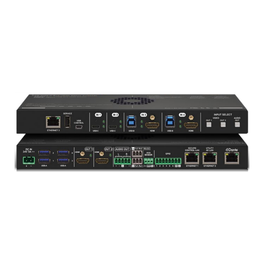
Front View (UCX-4x2-HC30D)
")
| 1 | Configurable Ethernet Port | RJ45 connector for configurable 100Base-T Ethernet communication. |
| 2 | USB-A Port | The service function will be added by future firmware update. |
| 3 | USB mini-B Port | The firmware upgrade function will be added by the future firmware upgrade. |
| 4 | USB-C Port | Displayport 1.2 and USB 3.1 Gen1 connections, AV signal can be transferred up to a resolution of 4K@60Hz 4:4:4 and data speeds up to 5 Gbps with remote charging. Use cables certified for USB 3.1 Gen1 (5Gbps) and Displayport Alternate mode HBR2 (4x5.4Gbps) applications. |
| 5 | Video Input Status LEDs | See the details in the table on the right. |
| 6 | USB-B Port | Upstream ports for connecting USB host devices (e.g. computer). |
| 7 | USB Status LEDs | See the details in the table on the right. |
| 8 | HDMI Input Ports | HDMI input ports for sources. The applied cable shall not be longer than 5m (22AWG) when signal resolution is 4K. Use cables certified for HDMI 2.0 (3x6Gbps) applications. |
| 9 | Input Select Button | For more details about the button functionality, see the table on the right. |
Arrangement of the Status LEDs

Rear View (UCX-4x2-HC30D)
")
| 1 | DC Input | The device can be powered by an external 120W power supply. Connect the output to the 2-pole Phoenix® connector. For more info about the powering, see powering options below. |
| 2 | USB-A Port | Downstream ports for connecting USB peripherals (e.g. camera, keyboard, multitouch display) with USB 3.1 Gen1 data speed. |
| 3 | HDMI Output Ports | HDMI output ports for connecting to the sink devices. |
| 4 | Video Output Status LED | See the details in the table on the right. |
| 5 | Analog audio port | Audio output port (5-pole Phoenix) for balanced analog audio output signal. The signal is de-embedded from the selected video signal. |
| 6 | RS-232 ports | This function will be added by future firmware update. |
| 7 | OCS sensor | 3-pole Phoenix® connector (male) for connecting an occupancy sensor. The port provides 24V output voltage (50mA). |
| 8 | GPIO | 8-pole Phoenix® connector for configurable general purpose. |
| 9 | Secure Control LAN | RJ45 connector for configurable 100Base-T Ethernet communication. |
| 10 | Utility AV LAN | RJ45 connector provides room utility Ethernet connection for e.g BYOD laptops. |
| 11 | Dante® Audio Output | In UCX-4x2-HC30D model: RJ45 connector for de-embedding the HDMI audio which can be transmitted as a 2-channel Dante® or AES67 source. |
 Always use the supplied power supply. Warranty void if damage occurs due to use of a different power source.
Powering Options
UCX series switchers are designed to provide power delivery for the connected device over the USC-C connectors. The following operation modes are available:
- Charge one device on the chosen port with up to 60W. The other port can supply up to 5V/3A.

- Charge one device with 30W (in this case, the other USB-C port can supply 30W or 5V/3A)


Power profiles can be set with Lightware Device Controller Software or with LW3 protocol commands.
Button functionality

Push OUT1 to set the video input to the HDMI OUT1 port.
Push OUT2 to set the video input to the HDMI OUT2 port.
Push AUDIO OUT to set the audio source of the analog audio output.
The sequence is the following:

Reset to Factory Default Settings

To restore factory default values, do the following steps:
- Make sure the device is powered on.
- Press and keep pressed the VIDEO OUT2 button and unplug and plug the power connector.
- TheLEDs get dark, the device restores the factory default settings and reboots.
Front Panel LEDs
| Video Input Status LED (the upper one) | ||
 | on | There is a valid video signal on this port. |
 | off | There is no valid video signal on this port. |
 | blink at once | The port is selected by a button press. |
| USB Status LED (the below one) | ||
 | on | The USB Host connected and selected. |
 | off | No USB Host or deselected port. |
 | blinks at once | The port is selected by a button press. |
Rear Panel LEDs
| Video Output Status | ||
 | on | The video signal is present. |
 | off | The signal is not present or muted. |
Dante® Audio Out (in UCX-4x2-HC30D model)
| LED state | Left LED | Right LED | Function |
 | Off | Off | No power |
 | Solid green | Solid red | Dante is booting |
 | Blinking green | Solid green | Slave with sync (normal operation) |
 | Blinking green | Blinking green | Clock master (normal operation) |
 | Blinking green | Blinking red | Acquiring clock sync (normal operation) |
 | Alternating red/green | Alternating red/green | Identify (blinking for 6 seconds) |
 | Blinking red | Blinking red | Dante fail safe |
 | Blinking orange | Blinking orange | Dante is upgrading |
Mounting the Device
(with optionally available accessories)
The examples demonstrate the applications of UD Kit accessories:
- Insert the power supply and the switcher into the UD-Kit.

- Fix the UD-Kits under the desk by fastening the screws.


UD-Kit does not contain the fixing screws, they can be purchased from the local hardware store. 4x 4pcs M3-M5 metric or wood screws needed, M4 size is recommended.
The enclosure size of UCX-4x2-HC30D is larger than the UCX-4x2-HC30 model, so take care of choosing the proper sized UD-Kit.
To ensure the correct ventilation and avoid overheating, insert the switcher face down to the UD KIT to keep the ventilation holes free.
Mounting the Device with UD Kit Rack Shelf (with optionally available accessories)
The examples demonstrate the applications of UD Kit Rack Shelf accessories:

For fixing the device to a Rack shelf, use the screw supplied with the switcher.
Longer screw may touch internal parts and harm the device.
Factory Default Settings
| General | |
| IP address | Dynamic (DHCP is enabled) |
| Video | |
| Crosspoint setting | I1 on O1, I3 on O2 |
| HDCP mode (Input) | I1, I2: HDCP 1.4; I3,I4: HDCP 2.2 |
| HDCP mode (Output) | Auto |
| Signal type | Auto |
| Emulated EDID | F47 - (Universal HDMI with PCM audio) |
| Audio | |
| Crosspoint setting | I1 on O3 |
| Analog audio output levels | Volume (dB): 0.00; Balance: 0 (center) |
| Autoselect | Follow video O1 |
| USB | |
| USB-C Power Limit | Equal output power |
| DP Alternate Mode Policy | Auto |
| Port Power Role | Dual Role |
| Autoselect | Follow video O1 |
| D1-D4 Power 5V Mode | Auto |
Connecting Steps

USB-C Connect a USB-C source (e.g. BYOD laptop) to the USB-C input port.
The applied cable shall be certified for USB 3.1 Gen1 (5Gbps) and Displayport Alternate mode HBR2 (4x5.4Gbps) applications.
HDMI Connect an HDMI source (e.g. BYOD laptop or room PC) to the HDMI input port.
CATx Connect a device (e.g. BYOD laptop) to the Utility Ethernet port to access the Internet or local network.
USB USB Type-A: Optionally connect the USB device (e.g. Speaker phone).
USB Type-B: Optionally connect the USB host (e.g. PC).
HDMI Connect an HDMI sink (e.g projector) to the HDMI output port.
CATx Optionally connect the Secure Control Ethernet port to a Local Network Switch to provide Ethernet connection for device configuration and BYOD internet access.
Audio Optionally connect an audio device (e.g. active speakers) to the analog audio output port by an audio cable.
GPIO Optionally connect a device (e.g. TBP6-EU-K button panel) to the GPIO port.
OCS Optionally connect an occupancy sensor to the OCS port.
Power Connect the external power supply to the AC power socket and the switcher unit.
 Powering the device is recommended as the final step.
Connecting USB-B and HDMI ports to the same PC or laptop is recommended in case of I3 and I4 inputs.
AV Port Diagram

* UCX-4x2-HC30D model has Dante® Audio Output.
USB Port Diagram

*For more details about the power delivery of the USB-C port see Powering Options section.
Device Concept

* In UCX-4x2-HC30D model
Software Control – Using Lightware Device Controller (LDC)
The device can be controlled from a computer using the Lightware Device Controller software. The application is available at www.lightware.com, install it on a Windows PC or a macOS and connect to the device via LAN.

Firmware Upgrade
Lightware Device Updater2 (LDU2) is an easy and comfortable way to keep your device up-to-date. Establish the connection via Ethernet. Download and install LDU2 software from the company's website www.lightware.com where you can find the latest firmware package as well.

Audio Cable Wiring Guide
The Taurus UCX series is built with 5-pole Phoenix output connectors. See below a few example of the most common assembling cases.
| Balanced output to balanced input Phoenix - 2x6.3 (1/4") TRS | Balanced output to balanced input Phoenix cable - 2x XLR plugs |
 |  |
| Balanced output to unbalanced input Phoenix - 2x RCA | Balanced output to unbalanced input Phoenix - 2x 6.3 (1/4") TS |
 |  |
GPIO (General Purpose Input/Output Ports)

The device has seven GPIO pins which operate at TTL digital signal levels and can be set to high or low level (Push-Pull). The direction of the pins can be input or output (adjustable). The signal levels are the following:
| Input voltage (V) | Output voltage (V) | Max. current (mA) | |
| Logic low level | 0 - 0.8 | 0 - 0.5 | 30 |
| Logic high level | 2 -5 | 4.5 - 5 | 18 |
Plug pin assignment 1-6: Configurable, 7: 5V (max. 500 mA); 8: Ground
The recommended cable for the connectors is the AWG24 (0.2 mm2 diameter) or the generally used 'alarm cable' with 4x0.22 mm2 wires.
The maximum total current for the six GPIO pins is 180 mA.
Contact Us
sales@lightware.com
+36 1 255 3800
support@lightware.com
+36 1 255 3810
Lightware Visual Engineering LLC.
Peterdy 15, Budapest H-1071, Hungary

Documents / Resources
References
Download manual
Here you can download full pdf version of manual, it may contain additional safety instructions, warranty information, FCC rules, etc.
Download Lightware UCX-4x2-HC30, UCX-4x2-HC30D - Switcher Quick Start Guide
Advertisement


Need help?
Do you have a question about the UCX-4x2-HC30 and is the answer not in the manual?
Questions and answers