Table of Contents
Advertisement
Quick Links
Advertisement
Table of Contents

Related Manuals for Midas XL8


Summary of Contents for Midas XL8
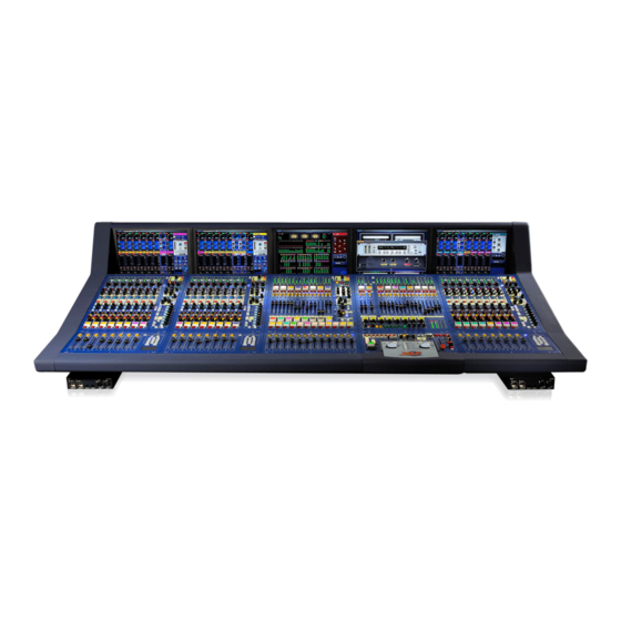
- Page 1 XL8 Control Centre Operator Manual...
- Page 3 Tel: +44 1562 741515 Fax: +44 1562 745371 Email: info@uk.telex.com Website: www.midasconsoles.com XL8 Control Centre - Operator Manual DOC02-XL8 Issue 2 - February 2007 © Telex Communications (UK) Limited In line with the company’s policy of continual improvement, specifications and function may be...
- Page 5 IMPORTANT SAFETY INSTRUCTIONS CAUTION RISK OF ELECTRIC SHOCK DO NOT OPEN WARNING: TO REDUCE THE RISK OF FIRE OR ELECTRIC SHOCK, DO NOT EXPOSE THIS APPARATUS TO RAIN OR MOISTURE AND OBJECTS FILLED WITH LIQUIDS, SUCH AS VASES, SHOULD NOT BE PLACED ON THIS APPARATUS OR EQUIVALENT.
- Page 7 Telex Communications (UK) Limited, Klark Teknik Building, Walter Nash Road, Kidderminster. Worcs. DY11 7HJ. England. Tel: +44 1562 741515 Fax: +44 1562 745371 www.midasconsoles.com EU DECLARATION OF CONFORMITY We, Telex Communications (UK) Limited of Klark Teknik Building, Walter Nash Road, Kidderminster, Worcestershire, DY11 7HJ, declare that a sample of the following product: Product Type Number Product Description...
- Page 9 Midas™ or Klark Teknik™ product, as well as other software that we provide for installation on the product. The Midas™ or Klark Teknik™ product will not operate in accordance with its documentation without this software.
- Page 10 Midas™ or Klark Teknik™ Software, developed by Company, that has been provided to you for installation on, or already installed in, your Midas™ or Klark Teknik™ Product. In addition to this Software, you may have also been provided, at no additional charge, a version...
- Page 11 • Any part that is damaged should be properly repaired or replaced. This must be done by a fully trained and authorised service engineer. • Observe all warnings, cautions etc. on any part of the equipment. • Do not remove, hide or deface any warnings or cautions. XL8 Control Centre Quick Reference Guide...
- Page 12 It is important that you don’t switch on or off two or more simultaneously. Before switching the XL8 on or off, please make sure that all monitor loudspeaker power amplifiers are turned off or muted. Handling the equipment Completely isolate the equipment electrically and disconnect all cables from the equipment before moving it.
- Page 13 Audio connections To ensure the correct and reliable operation of your XL8 Control Centre, only high quality balanced, screened, twisted pair audio cable should be used. XLR connector shells should be of metal construction so that they provide a screen when connected to the console and, where appropriate, they should have Pin 1 connected to the cable screen.
- Page 14 To comply with part 15 of the FCC Rules, any special accessories (that is, items that cannot be readily obtained from multiple retail outlets) supplied with this equipment must be used with this equipment; do not use any alternatives as they may not fulfil the RF requirement. XL8 Control Centre Quick Reference Guide...
-
Page 15: Table Of Contents
Chapter 3 XL8 Control Centre Description ....27 Bays ..........28 Control surface layout . - Page 16 VCA/POP groups ........92 XL8 Control Surface...
- Page 17 Lock screen ......... 142 XL8 Control Surface...
- Page 18 Warnings, cautions and important information ....153 Connecting up the XL8 ........154 Cable type and function .
- Page 19 Side chain ........201 To select a side chain source ......201 XL8 Control Surface Operator Manual...
- Page 20 Security (locking mode) ....... . .202 Locking the XL8 control centre ......202 Unlocking the XL8 control centre .
- Page 21 GEQ channel number allocation ......232 To connect the XL8/RapidE ......233 To set up the RapidE .
- Page 22 To re-map a GUI screen ......269 XL8 Control Surface Operator Manual...
- Page 23 XL8 system buses ........
- Page 24 Technical Specification ..... . 295 XL8 general statistics ........295 XL8 general specifications .
-
Page 25: Introduction
Chapter 1: Introduction The XL8 Control Centre is a user-friendly, state-of-the-art, high performance digital console that forms an integral part of the XL8 Live Performance System, which has been specifically designed for live use. The XL8 Control Centre comprises a combined control surface and graphical user interface (GUI) that provide an array of easy-to-use controls for precise manipulation of audio. -
Page 26: Warranty And Registration
About this manual Purpose This is the operation manual for the XL8 Control Centre. It is intended to help get your XL8 Control Centre installed and in operation as quickly as possible by giving you unpacking, installation, connection and setting up instructions. To help familiarise you with the XL8 Control Centre there is a description of the control surface and GUI, along with easy-to-follow instructions that show you how to perform basic operations. - Page 27 • Chapter 10 - Advanced Operation An in-depth guide on XL8 Control Centre operation. Also contains routine servicing information to help the user maintain the XL8 Control Centre in the best possible condition. • Chapter 11 - Graphic Equaliser (GEQ) Description and operation of the XL8 Control Centre’s internal graphic equaliser,...
-
Page 28: Conventions
Chapter 1: Introduction Conventions With many controls, pushbuttons, LEDs etc. being represented on the XL8 Control Centre in two ways, that is, on the actual physical control surface and the virtual representation as shown on the GUI, it is necessary to indicate which of these is to be, or is being, acted upon. -
Page 29: Page Layout
In some cases the preceding right-hand Manual information: first line describes (odd) page may be blank to the equipment that this manual refers accommodate this to and the second line gives the manual type XL8 Control Centre Operator Manual... -
Page 30: Signposts
Chapter 1: Introduction ‘Signposts’ To show you where on the XL8 Control Centre the page information refers to there are ‘signposts’ to guide you, of which there are two types, line drawings and symbols. The line drawings come in two sizes and represent the layout of the control centre. The smaller of the two merely identifies the control bay location, while the larger one shows all of the hardware controls and can pinpoint the smallest section. -
Page 31: Terminology
Performance System (due to the distributed nature of the product), the names on the control panels, GUI screens and I/O racks all correspond. To help with this, the primary buses on the XL8 are defined in Table 4 “Definition of primary buses” on page 199. - Page 32 Chapter 1: Introduction XL8 Control Centre Operator Manual...
-
Page 33: Xl8 Live Performance System Overview
AES50 digital audio, and uses readily available standard cabling and connectors. Along with the XL8 Control Centre there are four mic splitters, five I/O units, 10 DSP units, two routers and a Klark Teknik DN9331 RAPIDE that collectively form the standard XL8 Live Performance System configuration. - Page 34 Chapter 2: XL8 Live Performance System Overview Showfiles • USB connectors for show archiving. • Showfiles are both forward and backward compatible. Warranty Three years. Audio quality • Three mic pre amps per input FOH, monitor and broadcast. • Midas EQ (sound quality and ‘feel’).
-
Page 35: System Hardware
System hardware The standard XL8 Live Performance System comprises the following equipment: • XL8 Control Centre (1-off): Comprises five discrete, independent bays, each with its own power supply, surface modules, surface processor, GUI processor and GUI screen. The standard five-bay control centre has three bay types, input (3-off), mix (1-off) and output (1-off). -
Page 36: Network
- left and right - are identical (ignoring the DN9331 RAPIDE). The XL8 Control Centre, which forms the core of the XL8 Live Performance System, is directly connected to the local I/O units, DN9331 RAPIDE and routers (via the ‘snake’). -
Page 37: Foh And Mon
Figure 1: Basic interconnectivity of a standard XL8 Live Performance System FOH and MON The XL8 Live Performance System can be used as an FOH or a MON system. Also, by sharing the four mic splitters, these two types of system can be used in tandem, as shown in Figure 2 on page 14. - Page 38 24-channel bi-directional MidasNET Main Duplicate Multiple MidasNET links Main Local I/O units Duplicate 192-channel bi-directional MidasNET trunk link Main XL8 Control Centre Duplicate Figure 2: Typical XL8 Live Performance System FOH and MON set-up with interconnections XL8 Control Centre Operator Manual...
-
Page 39: Audio Physical Connections
Audio physical connections Audio physical connections The total number of audio connections, that is, the XLR count, for a standard XL8 Live Performance System is 504. This comprises of both dedicated and configurable XLR connections. The dedicated XLR connections are on the DL431 mic splitter and comprise: •... - Page 40 I/Os at mix position Figure 3: XL8 maximum system capacity (112 mic inputs) However, the XL8 can have much more than the standard connectivity by adding DL451 I/O units. As there are nine AES50 connections (fully redundant) available, potentially, another 432 audio connections can be achieved (subject to other system limits).
-
Page 41: Mix Matrix
Console linking Two XL8 Control Centres can be linked together, as you can with Heritage consoles. The bus outputs from one control centre feeds the bus inputs of the other, which is done using AES50 links. -
Page 42: Mix Channel Processing
Chapter 2: XL8 Live Performance System Overview Each of the 16 auxiliary inputs has: • Input gain. • Source from internal FX or external pool input. • Fader. • Panpot (SIS™). • Routing via level controls to the 16 matrix buses. -
Page 43: Output Channel Processing
• Insert point. • Direct input. Effects processing and GEQs The XL8 contains 16 mono Klark Teknik (KT) GEQs and 16 effects processors as standard. The 16 effects processors can be freely chosen from: • KT DN780 reverb. • Stereo delay. -
Page 44: Control Software
Resilience to failure (redundancy) The XL8 Live Performance System is tolerant of any single failure of hardware or software. To achieve this the system employs dual-redundancy, where a key component has an identical redundant spare that is ready to take over should it fail. - Page 45 Resilience to failure (redundancy) Local I/O units Internal bay processor Dual redundant XL8 Control Centre internal master controller Dual redundant internal router Control data Cat6/optical ‘snake’ Audio data N + 1 redundant Control and spare audio data Router Monitor This diagram gives a...
- Page 46 Chapter 2: XL8 Live Performance System Overview Local I/O units XL8 Control Centre Internal bay processor Red interconnections indicate that communications are Internal master healthy controller Internal router units I/O units Router This diagram illustrates an extreme Monitor example of dual...
- Page 47 Resilience to failure (redundancy) Local I/O units Internal bay XL8 Control Centre processor Internal master controller Internal router Greyed out Red interconnections interconnections indicate that indicate no communications are communication due healthy to fault in this side of system units...
-
Page 48: Integration Of Third Party Software
It also means that there is no need to find somewhere to put multiple keyboards and mice. Examples are: • ProTools. Right in the middle of the XL8! Link ProTools and XL8 audio digitally and use any ProTools plug-in as an insert to the XL8! •... -
Page 49: System Documentation
When shipped separately, each unit comes supplied with a printed and bound copy of its associated Quick Reference Guide. This is accompanied by a CD that contains all of the operator manuals listed in Table 1 “XL8 user documentation”, which gives full details of the XL8 Live Performance System. - Page 50 Chapter 2: XL8 Live Performance System Overview XL8 Control Centre Operator Manual...
-
Page 51: Xl8 Control Centre Description
Chapter 3: XL8 Control Centre Description The XL8 Control Centre is built on a robust Midas steel frame chassis similar to those used for established Midas analogue products. The frame houses five bays, each of which is a discrete hardware module that can operate independently of its neighbour. -
Page 52: Bays
Chapter 3: XL8 Control Centre Description Bays The XL8 control centre has five bays, of which there are three types: • Input Bays (3-off): Provide fast access to large numbers of faders and important input signal processing controls. The bays are numbered 1, 2 and 3, in order from left to right. -
Page 53: Control Surface Layout
- automation: scene store/recall and system edit. • - primary navigation zone: for mix bay and output bay GUI screen navigation via trackballs, and screen access panel for direct access to certain GUI screen menu options. XL8 Control Centre Operator Manual... -
Page 54: Gui
Chapter 3: XL8 Control Centre Description The XL8 Control Centre has a graphical user interface (GUI) that provides a backdrop to the control surface. The GUI comprises five screens that have been manufactured to a high specification to give good definition in areas of strong light. This allows their displays to be clearly visible in sunlight, which makes the XL8 ideal for outdoor performances. -
Page 55: Output Bay Gui Display
Pull-out keyboard Front and rear connections Connector panels on the front and rear of the XL8 Control Centre provide XL8 Live Performance System interconnections that allow connection of peripheral devices, such as keyboards, monitors, portable PCs, USB memory keys etc. - Page 56 Chapter 3: XL8 Control Centre Description XL8 Control Centre Operator Manual...
-
Page 57: Input Bays
GUI screen changes to the view dedicated to the new area the operator is accessing. • Input navigation zone: screen navigation and function selection via glide pad, and select input channels to screen via the input select section. XL8 Control Surface Operator Manual... -
Page 58: Input Signal Routing
Order can be swapped by clicking C/O on GUI screen; see page 43 Insert controls; see page 54 Equaliser; see page 56 Aux controls; see page 58 Matrix controls; see page 58 Master controls; see page 61 XL8 Control Surface Operator Manual... -
Page 59: Input Bay Control Surface
52) page Page Page E zone Page Page 56 Page Page Page Page Input navigation Page zone Glide pad (page 36) Fader section Input of input fast channel strip (page 61) select (page 66) XL8 Control Surface Operator Manual... -
Page 60: Input Bay Gui
On the control surface of any input Bank identifier shows the bank of channels bay, pressing a quick access button will activate its currently displayed. respective channel and select the appropriate section XL8 Control Surface Operator Manual... -
Page 61: Meters
Compressor gain reduction Dashboard display on the mix bay GUI seven-segment LED meter monitors the screen shows all meters. amount of gain reduction when using a compressor. XL8 Control Surface Operator Manual... -
Page 62: Mic Amp - Preliminary Input Processing
GUI input fast strip DL431Mic splitter control panel Mic input area (see page 44) Adjusts console digital trim or stage box input gain, depending on which is selected to the GUI input channel strip XL8 Control Surface Operator Manual... - Page 63 180° out remote stage box input gain. of phase. Stage box control knob adjusts input gain of For example, where two mics are facing each other remote amplifier in 2.5dB steps, ranging from -5dB to XL8 Control Surface Operator Manual...
-
Page 64: Channel Configuration
• Input channel delay: user-defined delay to be added to the input signal processing. • Input channel processing order: provides selection of whether the dynamics section or the EQ section comes first in the input channel signal path. XL8 Control Surface Operator Manual... -
Page 65: Input Channel Source (Gui Only)
LED on the mic splitter by illuminating to indicate that Red translucent circle identifies the current input a channel on the XL8 is selected to this input. source of currently selected channel. Moves 48V LED mimics the action of corresponding LED... -
Page 66: Input Channel Direct Output
AUTO channel safe switch removes channel from automation. snapshot automation system only, leaving Each input channel safes switch has an auto-mutes, VCA masters and assignment systems adjacent coloured LED that illuminates to show that active. the switch is on. XL8 Control Surface Operator Manual... -
Page 67: Input Channel Delay (Gui Only)
This section comprises a switch that selects whether the EQ or the dynamics comes first in an input channel’s signal path. Current status of the processing order is only available from the GUI. C/O switch changes order of processing from EQ/INS/DYN (default) to DYN/INS/EQ and vice versa. XL8 Control Surface Operator Manual... -
Page 68: Input Channel Gain And Filter
Chapter 4: Input Bays Input channel gain and filter This group of controls are digital and shouldn’t be confused with the mic splitter remote controls. XL8 Control Surface Operator Manual... - Page 69 30Hz filter but before any further processing. LINK switches pair adjacent channels for stereo operation by linking compressor side chains. Linkages are editable but default to those in Table 7 “Linking - input channels” on page 210. XL8 Control Surface Operator Manual...
-
Page 70: Direct Out
This section is deliberately distanced from main channel panel controls because it is a limited resource and unused on many channels. Selection of signal path position (item 4) and destination (item 5) can only be carried out via the GUI. XL8 Control Surface Operator Manual... - Page 71 Quick access button selects direct output Indication of whether “post-fade & mute”, section to the GUI input channel strip. “pre-mute, post-processing” or “pre-mute pre-processing” is in operation, as indicated by XL8 Control Surface Operator Manual...
-
Page 72: Compressor (D Zone)
D zone, while the GUI treats both devices separately. The device currently displayed on the GUI screen is the one currently controlled by the D zone dynamics section. For more details on the compressor, see “XL8 compressor modes (dynamic)” on page 272. - Page 73 Compressor/Gate select buttons allow you to flip Available compressor types, that is, corrective, between the compressor and limiter controls in the adaptive, creative and vintage; see “XL8 GUI detail area. compressor modes (dynamic)” on page 272 for Compressor make up gain control knob is used to details.
-
Page 74: Compressor Graph
A threshold reduction will move threshold point compression at selected ratio is applied and line colour to left, as shown in the example in graph C (green changes to red. line). Less signal is passed 1:1. Graph with ratio applied XL8 Control Surface Operator Manual... - Page 75 Compressor (D zone) Graph showing effects of threshold Graph with no ratio applied adjustment Graphs showing knee types Hard knee Medium knee Soft knee Graphs showing compressive display types Uncompressed Within knee area Fully compressed XL8 Control Surface Operator Manual...
-
Page 76: Gate (D Zone)
• Pressing MENU in the side chain section (see “Side chain” on page 64) opens the side chain selection dialogue in the GUI input channel strip. Unlike the compressor, the gate only has one style. D zone XL8 Control Surface Operator Manual... - Page 77 Once signal is detected as below threshold, this defines a waiting period before the gate starts to close. XL8 Control Surface Operator Manual...
-
Page 78: Insert
Quick access button provides a short cut to the screen menu used to select insert point (send and return) allocation from those available on the console system (in GUI input channel strip). Green assign LED illuminates to show that an insert is enabled. XL8 Control Surface Operator Manual... - Page 79 Insert XL8 Control Surface Operator Manual...
-
Page 80: Eq (E Zone)
These select which of the four bands the surface is controlling. All four bands are displayed on the screen - no matter what is selected - and selected area will be highlighted. E zone XL8 Control Surface Operator Manual... - Page 81 = blue; hi mid = green; lo mid = Indicates shape of the signal’s envelope. yellow; and bass = red. “OFF” is displayed to show that EQ is off. MODE button - shape selector on treble and bass peaking displays only. XL8 Control Surface Operator Manual...
-
Page 82: Auxes And Matrices
8 buttons to scroll in banks of eight. Each aux has a level control knob, and ON and PRE switches. Additionally, each pair of sends has an AFL switch in the input fast strip. XL8 Control Surface Operator Manual... - Page 83 (ramp style). When send is off, the bar display dims. The pair of auxes/matrices currently assigned to the input fast strip have their numbers highlighted in the control surface colour code of that pair. XL8 Control Surface Operator Manual...
- Page 84 (both -6dB to OFF). Stereo auxes level Pan adjustment is constant power law at -3dB. Level adjustment is continuous (+6dB to OFF). Subgroup Both levels are disabled. 0dB only for group buses, mix and main buses. XL8 Control Surface Operator Manual...
-
Page 85: Master Controls And Fader
AFL solos also operate as a default from the main solo switch.) Solo routing section (above fader) activates solo routing and selects which monitor section (A or B) signals are routed to. XL8 Control Surface Operator Manual... - Page 86 Chapter 4: Input Bays XL8 Control Surface Operator Manual...
- Page 87 Constant power is maintained at all times so that the ‘image’ can be adjusted during the show without a perceived change in level. XL8 Control Surface Operator Manual...
-
Page 88: Side Chain
Side chain graph shows the effects (three options). of the processing on the signal. MENU/S/C side chain filter menu access switch, when enabled, accesses a pop-up window (see “Side chain” on page 201), after which the glide path or XL8 Control Surface Operator Manual... -
Page 89: Select Side-Chain Source Window
3. Choose Pick-Off Point... panel gives you available pick-off points from which to choose where the side chain will exit from. CANCEL button exits the window without selecting the side chain source. XL8 Control Surface Operator Manual... -
Page 90: Input Channel Select
This provides the facility for two-man or split-surface operation; see “To configure the XL8 for split surface/dual operation” on page 205. This is also supported by the solo system with solo B. -
Page 91: Mix Bay
GUI screen support. The mix fast zone supports auxes, returns and mixes. At the simplest level of operation these are paged in banks of 16 to the eight mix fast strips. XL8 Control Centre Operator Manual... -
Page 92: Mix Bay Control Surface
VCA and POP group Page VCA fader and solo section (page 91), which forms part of VCA and POP group (page 92), which the VCA and POP also includes VCA fader and solo group section XL8 Control Centre Operator Manual... -
Page 93: Mix Bay Gui
B button has Backlit GUI trackball moves cursor around the been enabled. mix bay GUI screen. Red rectangular mute indicator (on every meter) illuminates when associated mute button has been enabled. XL8 Control Centre Operator Manual... -
Page 94: Mix Fast Strip
Talk section for selecting bus that talk signals are routed to. Note: Meters can be switched, under global command, from the main output bay area to monitor the raw A/D input point and are also individually switchable via the channel panel. XL8 Control Centre Operator Manual... -
Page 95: Lcd And Solo
Left-hand button (8a) selects odd numbered channel to the left and right-hand button (8b) selects even numbered channel to the right. With both channels linked for stereo, both buttons operate on the pair. XL8 Control Centre Operator Manual... -
Page 96: Faders
Chapter 5: Mix Bay Faders Fader controls the mix channel signal level and is motorised to provide instant feedback of level settings. Faders are colour coded for ease of identification. XL8 Control Centre Operator Manual... -
Page 97: Auxes
These two buttons (on output channel strip of the mix bay) page the output section to address the auxes. This diagram shows the controls that are operational when the aux sends are paged to the output section. XL8 Control Centre Operator Manual... -
Page 98: Configuration Controls
Aux name field displays fixed aux name on the “0” gives no delay. left- and operator-configured aux name on the right- hand side. stereo linking switch pairs selected channel with adjacent right-hand channel. This switch is only appears on odd numbered channels. XL8 Control Centre Operator Manual... -
Page 99: Direct Input Controls
Aux direct input SOLO switch view to an external source (connector on activates signal routing to the Monitor A rear of control centre) section of the console. Aux direct pre MODE button changes the input point for the signal. XL8 Control Centre Operator Manual... -
Page 100: Dual Dynamics, Side Chain And Talk Mic
(see “Compressor (D zone)” on page 48), with the addition of Shimmer.. Press this quick access button to select the compressor/gate dynamic section to the GUI output channel strip XL8 Control Centre Operator Manual... - Page 101 Available compressor types, that is, corrective, ratio control knob adjusts amount of adaptive, creative, vintage and shimmer; see compression applied to signals below threshold. “XL8 compressor modes (dynamic)” on page 272 for details. XL8 Control Centre Operator Manual...
-
Page 102: Insert Controls
LED illuminates to show that an insert is in use. Quick access button selects insert section to GUI output channel strip to allow configuration of insert send and return points. XL8 Control Centre Operator Manual... -
Page 103: Parametric Eq
Bands 1 to 4 (as in this example) or Bands 3 to 6. GEQ button takes you to the GEQ rack; see ..Graph showing effects of parametric EQ. XL8 Control Centre Operator Manual... -
Page 104: Matrix Outputs
Note: ON and PRE switches on odd numbered channels do not operate when buses are in stereo mix mode. Press this quick access button to select the matrix section to the GUI output channel strip XL8 Control Centre Operator Manual... - Page 105 They operate as level-and-level for mono buses and pan-and-level for stereo buses. XL8 Control Centre Operator Manual...
-
Page 106: Faders And Masters
The principles of operation of the masters section is basically the same as for the equivalent section on each of the input strips, see page 61. Press this quick access button to select the masters section and faders to the control surface XL8 Control Centre Operator Manual... - Page 107 In SIS mode, this image control modifies pan control knob operation to place channel within a three-speaker system. With mono level SIS image control knob turned fully clockwise, pan operates in full LCR, where centre panned signal (pan set to c XL8 Control Centre Operator Manual...
-
Page 108: Returns
Diagram below shows the return-related control surface areas on the mix bay. This button pages the output section to address the returns. This diagram shows the controls that are operational when the returns are paged to the output section. XL8 Control Centre Operator Manual... -
Page 109: Configuration Controls
Only appears on odd numbered channels. Source of return, assignable via the drop-down list, which is accessed by clicking on the adjacent down arrow. XL8 Control Centre Operator Manual... -
Page 110: Matrix Outputs
Yellow box indicates that this pair are sourced from the selected sub mix. They currently selected to the control surface. operate as level-and-level for mono buses and pan-and-level for stereo buses. PRE switch switches each level matrix control to pre-fader. XL8 Control Centre Operator Manual... - Page 111 Returns XL8 Control Centre Operator Manual...
-
Page 112: Faders And Masters
The principles of operation of the masters section is basically the same as for the equivalent section on each of the input fast strips, see page 61. Press this quick access button to select the masters section and faders to the control surface XL8 Control Centre Operator Manual... - Page 113 In SIS mode, this image control modifies pan control knob operation to place channel within a three-speaker system. With mono level SIS image control knob turned fully clockwise, pan operates in full LCR, where centre panned signal (pan set to c XL8 Control Centre Operator Manual...
-
Page 114: Bank/Channel Selection
Moves are shown on the control surface. (You can even scroll across stereo, mono and matrix channels on the output bay). XL8 Control Centre Operator Manual... -
Page 115: Vca Faders
VCA masters. AREA B button changes input channel selection from default (area “A”) to those input channels set to area “B” mode, in bays configured to present input channels to the user. XL8 Control Centre Operator Manual... -
Page 116: Vca/Pop Groups
(area “A”) to those input channels set to the channel mute status indicator. area “B” mode, in bays configured to present input channels to the user. XL8 Control Centre Operator Manual... -
Page 117: Output Bay
The output fast zone supports matrix and master outputs, which are effectively the same thing. Functionality and operation of the output bay are closely connected to mix bay; see page 67 for further details. XL8 Control Surface Operator Manual... -
Page 118: Output Bay Control Surface
Master overview strips (page 97) Output bay I zone Comms Monitors Primary navigation zone contains trackballs for mix bay GUI screen (left) and output bay GUI screen (right); see page 96 Matrix overview strip (page 102) XL8 Control Surface Operator Manual... - Page 119 Output bay control surface Comms (page 106) Reset switches Output bay (page 106) Mute groups (page 118) Monitoring (page 116) Automation (page 117) Monitoring (page 116) Monitoring (page 110) XL8 Control Surface Operator Manual...
-
Page 120: Output Bay Gui
Channel Sheet and Output Channel Sheet screens. • monitors/preferences – takes you to the Mouse mat area when using an external mouse. Monitors and General (Preferences) screens. • vca’s/assignable controls – takes you to the Groups Sheet screen. XL8 Control Surface Operator Manual... - Page 121 Output bay GUI XL8 Control Surface Operator Manual...
-
Page 122: Master Overview Strips
Chapter 6: Output Bay Master overview strips The two master overview strips contain the stereo and mono master channels. XL8 Control Surface Operator Manual... - Page 123 LEDs illuminate to show that listen is active in output detail area. DYN switches for left and right channels (stereo) or single channel (mono) switch the dyanmics on/off. Each have and integral LED that illuminates to show that dynamics is on. XL8 Control Surface Operator Manual...
- Page 124 Chapter 6: Output Bay XL8 Control Surface Operator Manual...
- Page 125 Illuminates to confirm adjustment of master output levels from +10dB to this action. In addition to scene recall it can also be off (4). remotely muted from auto-mute masters. XL8 Control Surface Operator Manual...
-
Page 126: Output Fast Strips
Chapter 6: Output Bay Output fast strips There are eight dual-channel output fast strips in the output bay’s fast zone. These house the output matrix mix masters. XL8 Control Surface Operator Manual... - Page 127 (integral LED) to prompt the operator to select a bus that the talk signals should be routed to. These are also used to set up a talk group after pressing one of the talk/osc routing panel buttons. XL8 Control Surface Operator Manual...
- Page 128 Chapter 6: Output Bay XL8 Control Surface Operator Manual...
- Page 129 MUTE mutes all post processing signals leaving the control surface (output fast zone). the output channel. Illuminates to confirm this action. In addition to scene recall it can also be remotely muted from auto-mute masters. XL8 Control Surface Operator Manual...
-
Page 130: Reset Switches
The controls in this area are not affected by automation. XL8 Control Surface Operator Manual... -
Page 131: Talk Mic
“Dual dynamics, side chain and talk mic” on page 76. Range is +15dB to +60dB and operates in conjunction with the peak limiter. XL8 Control Surface Operator Manual... -
Page 132: Signal Generator
50Hz to talk group; see “talk osc/routing” on page 109. 5kHz. level control knob gives continuous adjustment of signal generator peak output signals from +10dB to off (4) XL8 Control Surface Operator Manual... -
Page 133: Talk Osc/Routing
“Talk Groups screen” on page 136. fast strips (see page 70) or output fast strips (see Four fixed bus talk group switches. page 102). ALL switch routes the talk/OSC internal signal to all outputs. XL8 Control Surface Operator Manual... -
Page 134: Monitoring
“Monitors” on page 202 for more details. intercom and USB keys Notes: As the intercom system in the XL8 Control Centre is a Telex RTS system (compatible with any TW system), the belt packs will require an RTS power supply. If you are using non-Telex RTS components you will need adaptors. -
Page 135: Solo System
Each of these modes changes the interleaving logic between differing areas of the monitor output. A mode select button scrolls through the possible options. Additionally, there is a solo in place switch for activating the SIP function. XL8 Control Surface Operator Manual... - Page 136 SOLO button press activates a mute of all other channels by temporarily overriding the primary source selection, XL8 Control Surface Operator Manual...
-
Page 137: Source And Output (A And B)
‘primary’ choice of stereo master (ST), mono master (MONO) or external (EXT). Additionally, there are talk back A and B switches. The monitor outputs, output a and output b, have some common control types for A and B; see “Monitors” on page 202. XL8 Control Surface Operator Manual... - Page 138 Integral LED illuminates to show that 4.5dB loss. Each has an integral LED that illuminates switch is on. to show that switch enabled. ST switch routes post-fader stereo master mix to stereo local monitor outputs. XL8 Control Surface Operator Manual...
-
Page 139: Afl, Pfl And Talk Back
Ranges from infinity (∞) to +10dB. PFL audio bus may level. Ranges from infinity (∞) to +10dB. accept injected external signals. afl level control knob adjusts the after-fader level. Ranges from infinity (∞) to +10dB. AFL audio bus may accept injected external signals. XL8 Control Surface Operator Manual... -
Page 140: Monitor A And B Output Panel And Meters
= fader control and off = no fader control. Non-automated fader for control of output level from +10 to -∞ on monitor a section. Stereo left and right peak level meters for monitor a and b sections. XL8 Control Surface Operator Manual... -
Page 141: Automation
(highlighted in green) in the cue list. Button displays “Next” when there is a next scene available, and “End” is displayed when the currently selected scene is the last in the cue list. XL8 Control Surface Operator Manual... -
Page 142: Auto-Mute Groups
• Recalling a scene that assigns an already active auto-mute. An auto-mute off can happen because of: • Deactivating all of the assigned auto-mutes. • Unassigning all of the active auto-mutes. • Recalling a scene that de-assigns all of the active auto-mutes. XL8 Control Surface Operator Manual... -
Page 143: Gui Menu Options
Chapter 7: GUI Menu Options The GUI is a very powerful multi-functional tool that forms the core of the XL8 Control Centre. It gives total control and monitoring of the operating environment, enhances control surface operation (you can even operate the XL8 by GUI-only) and allows the use of internal and external devices. -
Page 144: Gui Menu Overview
Admin screen (page 143) Indicates that the screen can be accessed directly via the screen access buttons in the primary navigation zone; see “Output bay GUI” on page 96 Shutdown System screen (page 143) Lock screen (page 142) XL8 Control Centre Operator Manual... -
Page 145: Gui Menu Flowchart
“57-64” or “Aux Sends 17-32”, the GUI channel strip in the subsequent screen will be blank. However, if a single channel is selected from a sub-submenu, for example, input channel 5 (IN5), the detail area already in the channel strip will be retained for the new selection. XL8 Control Centre Operator Manual... -
Page 146: Menu Option Identification
Default screen home Default This takes you to the default screen for the bay you are in, that is, input, mix or output. This is configured in the Preferences option; see “Preferences screen” on page 139. XL8 Control Centre Operator Manual... -
Page 147: Files Screen
USB memory stick is plugged in. Immediately after plugging in a USB memory key, you will probably see the message “Analysing...”, while the contents of the storage media is being read. XL8 Control Centre Operator Manual... -
Page 148: Input Channels Screen
Takes you to the Input Channel Sheet screen (page 124) Takes you to any of the 96 inputs (banks of eight). See page 125 for inputs 1 - 8. XL8 Control Centre Operator Manual... -
Page 149: Input Channel Sheet Screen
This input channel screens show all of the controls for the input channels. To encompass the 96 channels, there are 12 screens in banks of eight channels. As the screens are similar, only the bank 1-8 screen is shown here. Refer to “Input bay GUI” on page 36. XL8 Control Centre Operator Manual... -
Page 150: Mix & Outputs Screen
1 - 8. Takes you to the Matrix Outputs 1 - 16 screen (page 129) Takes you to the Master Outputs 1 - 16 screen (page 129) Takes you to the Dashboard screen (page 130) XL8 Control Centre Operator Manual... -
Page 151: Output Channel Sheet Screen
(item 1), which also becomes the 16-off Matrix. backlight colour of its LCD select switch. Control knob icon: takes you to the output channel’s associated bank of channels, which can also be accessed via the other options in the submenu. XL8 Control Centre Operator Manual... -
Page 152: Aux Returns 1-16 (Mix Channels) Screen
There are two Aux Sends screens that encompass the 32 auxes, each in banks of 16 channels. The Aux Sends 1 - 16 screen shows all of the controls for the auxes channels; see “Auxes” on page 73. XL8 Control Centre Operator Manual... -
Page 153: Matrix Outputs 1 - 16 Screen
The Matrix Outputs 1 - 16 screen shows all of the controls for the matrices. Refer to “Output fast strips” on page 102. Master Outputs screen The Master Outputs screen shows all of the controls for the masters. Refer to “Master overview strips” on page 98. XL8 Control Centre Operator Manual... -
Page 154: Dashboard Screen
Returns (returns), 32 Aux Sends (auxes), three channel display screen. Masters (L, R and M), Mon A and Mon B (A and B monitors - stereo L and R) and 16 Matrix Outs. Three ‘virtual’ analogue meters give signal level indication. XL8 Control Centre Operator Manual... -
Page 155: Population Groups Screen
The top half, which is common to all three groups screens (see “Group management” on page 132) deals with the group management, while the bottom half contains the group controls, which can generally be found on the control surface’s fast zones. XL8 Control Centre Operator Manual... -
Page 156: Group Management
These are now no longer members of the group. Name of selected group. XL8 Control Centre Operator Manual... -
Page 157: Group Sheet Screen
LCD select switch. mute group select (LCD) switches; see “Mute Groups Control knob icon: takes you to the group’s screen” on page 135. associated editing screen, which can also be accessed via the other submenu options. XL8 Control Centre Operator Manual... -
Page 158: Vca Groups Screen
91. Active when highlighted by yellow of VCA group. bounding box. The MUTE, SOLO, MUTE and FDR safes buttons and the fader have the same functionality as that of their group members’, but apply to the whole group. XL8 Control Centre Operator Manual... -
Page 159: Mute Groups Screen
“Auto- mute groups” on page 118. Active section is MUTE button has similar functionality to that of highlighted by yellow bounding box, as shown. its group members’, but applies to the whole group. XL8 Control Centre Operator Manual... -
Page 160: Talk Groups Screen
Talk group ID (fixed) and user-configured talk Talk group section corresponds to talk osc/ group name. routing section on control surface; see “talk osc/ routing” on page 109. User-assignable talk group button. Yellow bounding box indicates the currently active section. XL8 Control Centre Operator Manual... -
Page 161: Rack Units Screen
Rack Units screen Rack Units screen The Rack Units screen is used to configure the two types of ‘virtual’ rack unit available on the XL8, that is, effects and GEQs. Takes you to the Effects Sheet screen (page 138) Takes you to the Graphic EQs screen;... -
Page 162: Effects Sheet Screen
Effects Sheet The Effects Sheet screen allows you to change the name and background colour of the 16 Graphic EQs and 16 Effects (FXs), as they appear elsewhere on the XL8 Control Centre. GEQ icon: shows that this item is associated with Graphic EQs section allows you to configure the a GEQ. -
Page 163: Automation Screen
266. Preferences screen The Preferences option has two submenus that allow you to set up certain parameters on the XL8 and to set up linking preferences. Takes you to the General screen (page 140) Takes you to the Linking screen... -
Page 164: General Screen
DSP timeout to between 10 and 600 seconds. parameters such as input channel insert. Meter Preferences section allows you to the time for meter parameters, such as decay and attack, and also to switch them on or off. XL8 Control Centre Operator Manual... -
Page 165: Linking Screen
Preferences screen Linking screen home Preferences Linking This screen gives channel linking options, such as safes, dynamics, EQ etc., which you can select/deselect to suit your linking preferences. XL8 Control Centre Operator Manual... -
Page 166: Lock Screen
Lock The Lock, or ‘splash’, screens are displayed across the GUI when the control centre is locked by selecting this option. Unlock button (on each screen): press to unlock screens Displayed across the five screens XL8 Control Centre Operator Manual... -
Page 167: Admin Screen
GUI screen. Inside the window is a “Shutdown ENTIRE system ?” message and an OK button and a CANCEL button from which you can select to shutdown the system or cancel the shutdown, respectively. XL8 Control Centre Operator Manual... - Page 168 Chapter 7: GUI Menu Options XL8 Control Centre Operator Manual...
-
Page 169: Connections, Setting Up And Powering Up
Description of the XL8 connections Front and rear connector panels The XL8 has connector panels on the front and rear that house numerous types of connector, which cater for the connection of mains power leads, 19” rack units, USB memory keys, keyboards, headphones, talk mics, communications, external monitors (input and output), KVM (keyboard, video and mouse) switches, intercoms, AES3 synchronisation, word clocks (75R) and monitors. -
Page 170: Front Panel Connections
Chapter 8: Connections, Setting Up And Powering Up Front panel connections There are two similar connectors panels at the front of the XL8 Control Centre, situated at either end under the armrest. Both panels house connectors for: • Keyboards for control via a GUI screen. Each keyboard socket is dedicated to a GUI screen;... -
Page 171: Keyboard Connections And Bay Allocation
Description of the XL8 connections Keyboard connections and bay allocation You can connect a keyboard to the mix bay and any of the input bays. To do this there are four USB connectors on the front of control centre. These are housed in two panels (two/panel) at either side. -
Page 172: Rear Panel Connections
Chapter 8: Connections, Setting Up And Powering Up Rear panel connections The rear of the XL8 Control Centre contains the monitor connector panels. Five monitor connector panels; see System interconnection panel; see page 149. page 151. Power supply panel; see page 152. -
Page 173: Monitor Connector Panels
Description of the XL8 connections Monitor connector panels There are five connector panels on the rear of the control centre - one per bay - that each contain two 15-way D-type connector(s), except the output bay, which only has one. These connectors allow you to attach an external monitor or laptop PC/tablet to the control centre. -
Page 174: Kvm, Monitor And Synchronisation Connector Panel
(female XLR) and an input (male XLR) AES3 sync section comprising X and Y socket, and left and right intercom remote input (female) and output (male) XLR (female XLR) sockets. sockets. talk section has a male XLR output socket. XL8 Control Centre Operator Manual... -
Page 175: System Interconnection Panel
Description of the XL8 connections System interconnection panel Green LED illuminates to Red LED illuminates to indicate no indicate communication communication optical and CAT6e X and Y sockets for Three X and Y Ethernet control sockets optical male and female Ethernet XLR (numbered 1 to 3) for female Ethernet XLR connectors, respectively. -
Page 176: Power Supply
Mains fuse, one for each bay. Specification is printed underneath: “FUSE: PowerCon® connector for bays 1, 3 and 5. 5x20mm; T10A L250V”. PowerCon® connector for bays 2 and 4. Neutrik PowerCon® mains socket. Bay ON/OFF switch, one for each bay. XL8 Control Centre Operator Manual... -
Page 177: Warnings, Cautions And Important Information
Description of the XL8 connections Warnings, cautions and important information XL8 Control Centre Operator Manual... -
Page 178: Connecting Up The Xl8
Chapter 8: Connections, Setting Up And Powering Up Connecting up the XL8 This diagram shows the network interconnections for a typical FOH XL8 system. FOH XL8 Control Centre - rear Note: All connections are dual redundant, so the system can operate quite normally using either the X or Y cables. - Page 179 Connecting up the XL8 Note: FOH rack For connections specific to the 19” rack units, please refer to their respective operator manuals Control centre AES50 audio X connectors to FOH rack I/O unit AES50 audio X connectors Control centre AES50 audio Y connectors to...
-
Page 180: Cable Type And Function
Chapter 8: Connections, Setting Up And Powering Up Cable type and function Table 3 below shows the type, terminations and function of the XL8 system’s interconnecting cables. Please read the table in conjunction with the network interconnections diagram on page 154. -
Page 181: Manual Set-Up Of Unit Ids
Manual set-up of unit IDs Manual set-up of unit IDs After connecting up your XL8 network system, you may need to set up the ID of each mic splitter, I/O box and DSP unit connected in the XL8 system (although they are normally factory configured). -
Page 182: Powering The Xl8 System
After all XL8 system interconnections have been made, start up the XL8 system: Make sure that all of the XL8 system equipment is switched off, that is, the XL8 Control Centre, speaker sub-system, DL431 mic splitters, DL451 modular I/O units, DL461 routers and DL471 DSP units. -
Page 183: Switching The Xl8 Control Centre On/Off
Control centre will boot up (see “Booting up” on page 160); the GUI will display the default screens and all the controls will be set to default. You are now ready to start using the XL8 control centre. XL8 Control Centre... -
Page 184: To Switch Off The Xl8 Control Centre
Cold boot determines the system configuration and sets up all the IP addresses and unit names. Hot boot is the normal mode of operation (even if the XL8 has just been loaded from a truck and is physically cold!). Hot boot uses the configuration and names stored in the system flash memory. -
Page 185: Basic Operation
XL8 Control Centre and how to get some audio out of it. For an in-depth guide on XL8 Control Centre operation refer to Chapter 10 “Advanced Operation”. The more advanced features of the XL8 are described in later chapters. -
Page 186: Hints And Tips
Hints and tips Check what is hidden On the XL8, please bear in mind that, unlike on an analogue control surface, some of the settings and parameters will be hidden from view (stored in the XL8’s computer memory). We recommend that, at various times during a mix, you select and view unused parameters to make sure there are no hidden surprises, for example, a reverb send left from a previous mix. -
Page 187: Working With The Controls
On the glide pad, you can also select by quickly double-tapping on the pad itself instead of using the select button, which may be more convenient as you only need to use one finger to complete the task. XL8 Control Centre Operator Manual... -
Page 188: Selecting A Detail Area To The Channel Strip Via The Gui
TALK, 48V etc. buttons in the gain trim section, is usually only indicated on the GUI, an example of which is shown below. PRE switch off PRE switch on XL8 Control Centre Operator Manual... -
Page 189: Lcd Buttons (Control Surface Only)
When moving the cursor over the inputs, callouts appear showing you the input ID followed by the user-configured name, for example, “IN5 Bass”. Underneath this will appear information on functions that are active, for example, “EQ: On”. XL8 Control Centre Operator Manual... -
Page 190: Faders
(towards the front) will operate to lock it in place. After use, unlock the catches by moving them up or down as appropriate (they work in opposite directions). Then slide the keyboard back underneath the output bay. XL8 Control Centre Operator Manual... -
Page 191: Digital Signal Path And Input Routing
There are no routing matrix functions required prior to mixing on the system. In this way the XL8 is not unlike a conventional analogue console, so if everything is plugged in, it should work. ‘Soft patching’ is easily carried via the GUI using diagrams of the mic splitter rear panels. -
Page 192: Navigating The Inputs
GUI in ascending order from left to right, irrespective of bay position. To help you understand the operating principles of the XL8 it may be best to visualise the control surface as if it were an analogue one, that is, in two dimensions with all 96 input channels laid out side by side. -
Page 193: To Select A Bank Of Input Channels
25-32 33-40 41-48 Input bay 2 Display changes to bank 33-40 33-40 41-48 49-56 Bank 41-48 is displayed on input bay 2’s GUI screen 41-48 49-56 57-64 Display changes to bank 49-56 XL8 Control Centre Operator Manual... -
Page 194: To Select An Input Channel By Typing In Its Number
25-32 33-40 41-48 This shows the bank containing channels 33-40 selected to input bay 2 (default configuration) Type the required channel number, for example, “5”. Press ENTER. Illuminated LED bank indicator will change position accordingly. XL8 Control Centre Operator Manual... -
Page 195: To Select An Input Channel Via A Switch Or Button
You stay on the same GUI screen, but scroll to the next bank Scrolls one channel Scrolls one channel to the left to the right See “To select a channel section to the GUI’s channel strip” on page 173. XL8 Control Centre Operator Manual... -
Page 196: To Select An Input Channel Via The Gui
Click button to select input channel. Note: On the glide pad, you can also carry out selection by using a single tap on the pad itself. XL8 Control Centre Operator Manual... -
Page 197: To Select A Channel Section To The Gui's Channel Strip
GUI channel strip, but does not deselect the channel. Other quick access control buttons For example, pressing this button in the compressor area of a channel will select the compressor section to the GUI channel strip XL8 Control Centre Operator Manual... -
Page 198: Setting A Mic Amplifier's Input Gain
Chapter 9: Basic Operation Setting a mic amplifier’s input gain The XL8 Control Centre has two input gains per channel, one is the remote gain for the DL431 mic box (stage box gain) and the other is the digital trim (console gain); see “Mic amp - preliminary input processing”... -
Page 199: Setting The High And Low Pass Filters
Stage box hi pass: The remote stage box contains a 12dB/Oct 30Hz filter. It is recommended that this is used at all times for optimum A/D performance. However, it may be bypassed if extremely low frequency performance is required, for example, when testing the system. XL8 Control Centre Operator Manual... -
Page 200: Input Equalisation (E Zone)
(bright, classic and soft) and bass (deep, classic and warm). Note: “Bright” and “Deep” use psychoacoustic phenomena to generate steep slopes that sound natural. These filters are called “minimum harmonic disruption filters”. XL8 Control Centre Operator Manual... -
Page 201: Input Dynamics Processing (D Zone)
(D zone)” on page 48. You could set up a limiter by using a high threshold and a steep ratio (greater than 5:1). Audition different algorithms (hard knee, medium knee and soft knee) using the KNEE button. Try different compressor types (corrective, adaptive, creative and vintage) using the MODE button. XL8 Control Centre Operator Manual... -
Page 202: To Set Up A Gate
Press the quick access button in the gate section to select the gate section. Apply processing by using the controls in D-zone, such as, attack, release, threshold, ratio/range and hold. See “Gate (D zone)” on page 52. XL8 Control Centre Operator Manual... -
Page 203: Vca/Pop Groups
Release the VCA group select button. The VCA group now contains the input channel members you have just selected. To recall the VCA group, see “To recall a VCA/POP input group” on page 181. Input channel select buttons XL8 Control Centre Operator Manual... -
Page 204: To Set Up The Name And Colour Of A Vca/Pop Group
Assign a backlight colour to the VCA group select button and background of name field on GUI by: a) Clicking on the palette icon. b) Clicking on your chosen colour to select it, for example, blue. XL8 Control Centre Operator Manual... -
Page 205: To Recall A Vca/Pop Input Group
If any of these LEDs flash, it means there are current VCA/POP group members within the respective bank(s) that are not selected to the control surface. XL8 Control Centre Operator Manual... -
Page 206: To Recall A Vca/Pop Output Group
To deselect the VCA/POP group, press its group select button again; settings revert to those when group select button was previously pressed. Recalling another VCA/POP group immediately deselects the one currently selected. XL8 Control Centre Operator Manual... -
Page 207: Navigating The Outputs
To select a bank of returns or auxes to the mix bay control surface, press RET or AUX as required. Pressing a bank select button selects that bank to the control surface. This is confirmed by its associated LED in the detail active section being illuminated. XL8 Control Centre Operator Manual... -
Page 208: To Select An Output Channel
First press selects selects aux 2 aux 1 Scrolls left by one channel Scrolls right by one channel Only one of these LEDs will be highlighted to show which bank is currently selected to the control surface XL8 Control Centre Operator Manual... -
Page 209: Setting Up A Mix
Setting up a mix Setting up a mix XL8 has 32 configurable mix buses, each of which can be aux mixes, subgroups and mix minus. The aux mixes can also be set up as stereo pairs or mono. 16 matrix outputs can also be accessed directly from input channels via level controls, which gives the XL8 the ability to provide 48 discrete mixes, plus left, right and mono. - Page 210 Level indicators are bright on selected channel but dimmed on inactive/muted channels This transition point, where solid colours change to translucent, indicates 0dB across the eight auxes Matrix mix Aux mix XL8 Control Centre Operator Manual...
-
Page 211: To Program A Mix Preset
While still holding down the set upper button, repeat steps 1 and 3 for all other odd numbered mixes you with to select to the preset. Release set upper button. Presets are stored. XL8 Control Centre Operator Manual... -
Page 212: Setting Up The Effects Rack
In “Select Device Type” window, click on one of the changes by clicking on “X” at top right-hand corner of available device types, for example, “Phaser”. (The device window. effects in the list may be slightly different on your display, XL8 Control Centre Operator Manual... -
Page 213: Routing An Aux To An Effect Or Output
Click on the down arrow to the right of the aux output source field (adjacent to XLR socket) to obtain a drop-down list containing output source names. Click on the name of the output source you require, for example, the effect you have just set up in “Setting up the effects rack” on page 188. XL8 Control Centre Operator Manual... -
Page 214: Simple Routing To Master Stereo Outputs
To obtain audio, simply press the ST (stereo) button of an input fast strip in an input fast zone or in the output channel strip. Then, while making sure nothing is muted and master faders are up, you will have audio. XL8 Control Centre Operator Manual... -
Page 215: Scenes (Automation)
Click OK; control surface settings revert to default. You can now create and manage the scenes for your new show. Don’t forget to save at regular intervals. XL8 Control Centre Operator Manual... -
Page 216: To Save A Show
Chapter 9: Basic Operation To save a show The XL8 will indicate to you when there are show settings to be saved. It does this by changing the background colour of the SAVE button to red, as shown below. To save, simply click on the SAVE button. -
Page 217: To Store A Scene
“Store to empty scene” “Store to next scene” “Overwrite scene” You can use the keyboard to type in any useful scene information in the “Scene Notes” window, if you wish. Click OK to save the scene. XL8 Control Centre Operator Manual... -
Page 218: To Recall A Scene
When you reach the end of the cue list, it just wraps around to the beginning so you can continue from the start again. XL8 Control Centre Operator Manual... -
Page 219: Naming Inputs And Outputs
From here, set up the output name and colour; see “To set up This button takes you to the output channels the name and colour of a VCA/POP group” on page 180. screen; see page 183 for an example XL8 Control Centre Operator Manual... -
Page 220: Areas A And B (Split Surface/Dual Operation)
Areas A and B can now be used independently of each other. A typical configuration for area A and B operation is shown below, although any input bay can be used as area B. Area A Area B XL8 Control Centre Operator Manual... -
Page 221: Saving Your Show Files To Usb Memory Stick
USB memory stick. This provides a valuable back up should the one stored in the XL8 be lost, for example, due to inadvertent deletion or in the highly unlikely event of system failure. -
Page 222: Troubleshooting
1. The current method of resetting the master controllers involves the use of the reset buttons on the control surface. In future XL8 versions this procedure will be under software control and will be carried out via the GUI’s Diagnostics screen. -
Page 223: Advanced Operation
Chapter 10:Advanced Operation This chapter details the advanced operating procedures for the XL8 Control Centre. Please note that this chapter does not describe every operation, as some are very simple and can be completed, for example, just by the press of a button. In such cases the information you are looking for will probably be found in the bay description chapters, that is, Chapter 4 “Input Bays”, Chapter 5 “Mix Bay”... -
Page 224: To Set Up A Stereo Aux
MODE button. To set up a mix minus Referring to the procedure detailed in “To set up a mono aux mix” on page 185, select the mix minus bus mode using the MODE button. XL8 Control Centre Operator Manual... -
Page 225: Side Chain
(Clicking CANCEL exits without saving.) In the 1. Source From Channel of Type... panel, select the channel type of your side chain source. A list of available channels will appear in the adjacent panel. XL8 Control Centre Operator Manual... -
Page 226: Security (Locking Mode)
GUI-only function. Locking the XL8 control centre To lock the XL8 Control Centre, click on home at the top left-hand corner of one of the GUI screens to open the GUI menu. Then, click on the Lock option. None of the controls on the control surface will function and the XL8 Control Centre will be totally locked out. -
Page 227: Muting
(the mute button on the channel); SIP mutes only apply to input channels (the “If not SIP muted” exit condition from State 1 is always true for other channel types); and an “Auto mute on” and “Auto mute off” are achievable in several different ways. XL8 Control Centre Operator Manual... -
Page 228: Safes
- cancels all earlier solos to the same bus before it activates. • Solos can also be operated from a VCA master when the channel to which they belong is a member of that VCA; this is in addition to the local operation. XL8 Control Centre Operator Manual... - Page 229 SIP (that is, local button press, auto-mute or scene recall) remain muted regardless of the SIP status. On removal of the overriding mute, the mute is restored according to the current SIP status; see Figure 4 on page 203. XL8 Control Centre Operator Manual...
-
Page 230: Solo B
VCA master solos to which the input channel is assigned. To select a bay as area B See “Muting” on page 203. XL8 Control Centre Operator Manual... -
Page 231: Solo In Place (Sip)
The user-definable buttons can be set up (via control surface or GUI) to contain any combination of aux, audio sub-group, mix or master buses and could be used, for example, for grouping announcements or for talking to groups of artists in a monitor mix. XL8 Control Centre Operator Manual... -
Page 232: To Use Internal Talk Or Osc Routing
Setting up a talk group is done at the Talk Groups screen; see “Talk Groups screen” on page 136. Also refer to “talk osc/routing” on page 109. To configure a talk group (GUI only) See “Group Sheet screen” on page 133. XL8 Control Centre Operator Manual... -
Page 233: Control Groups
(bay). For example, you cannot link input channel 8 in one bank with input channel 9 in the next. Each LINK button has an integral LED that illuminates to indicate that adjacent input channels are linked. XL8 Control Centre Operator Manual... -
Page 234: Output Channels
Bus select All controls linked Main mute Not linked Main solo Not linked Solo B Linked Main pan Not linked Disabled - does not function in stereo ST master Linked Mono master Linked Fader Not linked XL8 Control Centre Operator Manual... -
Page 235: Service Information
The service manual for this equipment is available for purchase. Please contact your local distributor for details. Routine maintenance To help keep your XL8 Control Centre unit in good working order and to make sure it gives you optimum performance, we recommend that you carry out the following about once every month. -
Page 236: Equipment Disposal
WEEE legislation. The horizontal bar underneath indicates that the product was placed on the EU market after 13th August 2005. For WEEE disposal, see our websites at www.klarkteknik.com or www.midasconsoles.com for information. XL8 Control Centre Operator Manual... -
Page 237: Graphic Equaliser (Geq)
Chapter 11:Graphic Equaliser (GEQ) The XL8 Control Centre incorporates a graphic equaliser (GEQ), which is closely based on the Klark Teknik DN370 Graphic Equaliser. Up to 16 of these GEQs are available and are assigned and operated via a Graphic EQs screen on the GUI. -
Page 238: Front Panel Features
Each filter is adjusted via a control knob on the GUI screen; see “Operating the control knobs” on page 166. To audition the effect of the filters, either the EQ in/out switch (which will also bypass the GEQ) or the individual filter switch may be used. XL8 Control Centre Operator Manual... -
Page 239: Example Of System Connection
Example of system connection Example of system connection XL8 Control Centre Operator Manual... -
Page 240: Using The Geq
This is commonly achieved with the use of a real time analyser (RTA). As the frequency centres of the XL8 Control Centre conform to ISO standards, corrections can be made by sight directly from the RTA to the graphic. -
Page 241: Live Use (Mon)
12dB gain (depending upon the RANGE switch’s setting) to frequencies in that band. Placing the fader of any band at the extreme downwards position will apply either 6dB or 12dB of attenuation (depending upon the RANGE switch’s setting) to the frequencies in that band. XL8 Control Centre Operator Manual... -
Page 242: Equalising A System
A compromise may need to be made in an effort to equalise the sound for the whole area rather than just the centre FOH position. XL8 Control Centre Operator Manual... - Page 243 During the performance, the FOH or monitor engineer may want to have a microphone or solo signal feed for the RTA so that feedback may be easily detected and rectified. XL8 Control Centre Operator Manual...
-
Page 244: Effects Of Equalisation
Reduction of tape hiss and system noise. 1k25 to 8k governs overall clarity and definition. 10k, 12k5, 16k Cymbals and overall brightness. Too much boost causes sibilance. Reduction of tape hiss and system noise. XL8 Control Centre Operator Manual... -
Page 245: Audio Signal Path
Audio signal path Audio signal path XL8 Control Centre Operator Manual... -
Page 246: Proportional-Q Filter Response
Chapter 11: Graphic Equaliser (GEQ) Proportional-Q filter response A major consideration in the design of the XL8 Control Centre was determining the equaliser response. Proportional-Q equalisation (as used on previous Klark Teknik analogue graphic equalisers) offers some key advantages over Constant-Q equalisation. - Page 247 Q value. Figure 7: Symmetrical-Q equaliser ‘wide’ mode full boost and cut XL8 Control Centre Operator Manual...
- Page 248 Symmetrical-Q equaliser in its 'wide' mode, while as more boost or cut is applied, the response becomes sharper, giving a much more precise control of problem frequencies. Figure 9: GEQ response ±2dB boost and cut XL8 Control Centre Operator Manual...
- Page 249 (SPLs) to be used. The two notch filters further enhance the XL8 Control Centre's ability to precisely tune-out problem frequencies. The response of the notch filters was selected after careful listening to allow feedback to be eliminated quickly, but at the same time to be unobtrusive when in use.
-
Page 250: Applications
While very useful for conventional wedge monitors, this feature really comes into its own when combining in-ear and wedge monitors, allowing the response of each monitor subsystem to be tailored to suit the artist’s requirements. XL8 Control Centre Operator Manual... -
Page 251: Examples
The examples shown right illustrate how the filters can be used on their own and also in conjunction with the graphic equaliser to handle problems encountered in real world corrective EQ applications. XL8 Control Centre Operator Manual... -
Page 252: Corrective Use Of Notch Filters
(a) and two notch filters overlapped with an EQ band (b), each resulting in greater attenuation (c). Nearly 45dB of attenuation is possible when using the notch filters in conjunction with the EQ bands. XL8 Control Centre Operator Manual... -
Page 253: Eqing A Monitor Wedge
(a and b traces). The user may assume that subsonic frequencies are being attenuated by cutting the bottom faders but the graph shows that this is not the case. XL8 Control Centre Operator Manual... -
Page 254: Technical Specifications
400Hz, 500Hz, 630Hz, 800Hz, 1.00kHz, 1.25kHz, 1.60kHz, 2.00kHz, 2.50kHz, 3.15kHz, 4.00kHz, 5.00kHz, 6.30kHz, 8.00kHz, 10.0kHz, 12.5kHz, 16.0kHz, 20.0kHz Due to a policy of continual improvement, the Klark Teknik Group reserves the right to alter the function or specification at any time without notice. XL8 Control Centre Operator Manual... -
Page 255: Frequency Chart
Frequency chart Frequency chart XL8 Control Centre Operator Manual... -
Page 256: Using A Rapide With The Geqs
Chapter 11: Graphic Equaliser (GEQ) Using a RapidE with the GEQs The 16 GEQs on the XL8 Control Centre can be controlled remotely from a Klark Teknik DN9331 RapidE Graphic Controller (shown below). Any of the RapidE’s 128 channels (4 banks of 32 channels) can be dedicated to any one of the GEQ units shown on the GUI. -
Page 257: To Connect The Xl8/Rapide
Using a RapidE with the GEQs To connect the XL8/RapidE Connection between the XL8 Control Centre and RapidE is via a single Ethernet cable. Interconnection can be made with the RapidE and XL8 fully powered up. Rear of XL8 Red LED illuminated... -
Page 258: To Set Up The Rapide
Notes: Bank and channel buttons illuminate to show active selection. If a channel button is selected that is already allocated to a HELIX unit, it will flash. Turn left control knob to select “CONSOLE” mode. XL8 Control Centre Operator Manual... -
Page 259: Using The Rapide To Remotely Control The Xl8
Remote operation of the XL8 Control Centre’s GEQs via the RapidE is quite straightforward. Any of the 16 GEQs on the XL8 Control Centre will replicate fader positions and adjustments on the RapidE, provided they have been configured as the source of the RapidE’s active channel. - Page 260 Chapter 11: Graphic Equaliser (GEQ) XL8 Control Centre Operator Manual...
-
Page 261: Automation
The store/recall section is intended for fast operation during show time and rehearsals, and is mostly supported by front panel hard switches etc. System edit is comprised mainly of the scope and MIDI buttons down the left-hand side of the GUI screen (see page 238). XL8 Control Centre Operator Manual... - Page 262 Copy button for copying a selected scene - without having to recall it to the control surface - to another scene in memory. Brings up a window for selecting source and target scenes. XL8 Control Centre Operator Manual...
- Page 263 MIDI column shows if the MIDI option is Point scenes collapsed/expanded symbols. “+” selected. shows point scenes collapsed, while “-” shows point scenes are expanded. Edit column opens a window that allows scene name and notes editing, and Xfade setting adjustment. XL8 Control Centre Operator Manual...
-
Page 264: Automation Navigation
• Setting all faders to - infinity (- ) dB. • Setting all level controls to 0dB. Scope Allows all of the control centre’s safe settings for store and recall to be viewed and selected/deselected. XL8 Control Centre Operator Manual... -
Page 265: Midi Functions
MIDI messages are encountered. A common use of MIDI input is to receive the globally enabled MIDI output messages and allow automation systems on different consoles to Automation speed While full dynamic automation is not a requirement for this These are dealt with by the actual control surface/screen controls. XL8 Control Centre Operator Manual... - Page 266 Chapter 12: Automation XL8 Control Centre Operator Manual...
-
Page 267: Effects
Front and rear panel images of the effects device appear, superimposed on the effects rack. These images replicate the behaviour of its physical counterpart. Flanger effects device. Delay effects device. Phaser effects device. Virtual DN-780 effects device. XL8 Control Surface Operator Manual... -
Page 268: Effect Configuration
‘acoustic spaces’. The parameter controls give accurate adjustment of all reverberation parameters and allow the engineer to create unique acoustic environments of virtually any type. XL8 Control Surface Operator Manual... -
Page 269: Virtual Dn-780 Effects Screen
Rear panel; see “Rear panel - common” on See “Front panel - common element” on page 261. page 260. See “Front panel - common element” on See “Front panel - common element” on page 260. page 260. XL8 Control Surface Operator Manual... -
Page 270: Virtual Dn-780 Front Panel
On-Sound/Infinite Room. Range is from 0 to 9. current settings for the selected algorithm. PATTERN control knob controls the ‘density’ (f1) of early reflections. Selects the number and spacing of Early Reflections/ADT/ Multi-tap delays; ranges from 1 to 9. XL8 Control Surface Operator Manual... -
Page 271: Levels
Press the algorithm select button (see page 246) to highlight the algorithm you require; the LEDs to the left of the algorithms show which one is selected. The settings in the parameter display panel will update to suit the currently selected algorithm. XL8 Control Surface Operator Manual... -
Page 272: To Create A New Variation
To store new variations Each algorithm has its parameter settings stored in the XL8. When the Virtual DN-780 effect is used, the most recent settings for each algorithm are recalled. If you need to return to the current settings of any algorithm at any point in show, you can store them in the appropriate scene;... -
Page 273: Lf Key
Whenever a particular effect is first selected, parameters will always be set the same, giving a known reference point from which to create the exact effect required. Unused parameter displays are blanked in effects programs. XL8 Control Surface Operator Manual... -
Page 274: Modifying And Storing The Effect
• Try delays from 25 to 50ms. Short delays reduce the effect, long delays produce echo. • Direct signal must be added at a suitable level on the mixing console. Try 50/50 direct/effect mix on Pattern 1, must less direct on Pattern 5. XL8 Control Surface Operator Manual... -
Page 275: Multi-Tap Echo" Effect
• Correct pre-delay (‘loop length’) should be set before creating the effect as attempts to alter this later will usually destroy part of the recorded sound. • Remember to return level to ‘0’ immediately after used to avoid noise build-up. XL8 Control Surface Operator Manual... -
Page 276: Infinite Room" Effect
‘punchy’ mix. These effects work well on most instruments, but try “Non-Linear” for explosive snare sounds and “Reverse” on vocals. • The “Alive” program produces a more natural, live ambience, which is less coloured than the other two effects and has wide-ranging applications. XL8 Control Surface Operator Manual... -
Page 277: Technical Specifications
Clears unwanted reverberant signal. Input level control From 6dB gain to infinite attenuation. Headroom indicator 10-point LED display, 0dB to -27dB. Display Simultaneous display of all parameter information. Parameter selection and store functions are verified by individual LEDs. XL8 Control Surface Operator Manual... -
Page 278: Delay Effects
Rear panel; see “Rear panel - common” on Left input: left delay. page 261. Right input: right delay. See “Front panel - common element” on page 260. See “Front panel - common element” on page 260. XL8 Control Surface Operator Manual... -
Page 279: Front Panel
Range is 0 to 100, with 50 at top LF Damping control knob adjusts the LF dead centre. attenuation of delay repeats. Man/Tempo switch for selecting manual (delay times specified in ms) or tempo (delay times specified in 1/16th bar). XL8 Control Surface Operator Manual... -
Page 280: Flanger Effects
See “Front panel - common element” on page 259. page 260. Rear panel; see “Rear panel - common” on See “Front panel - common element” on page 261. page 260. See “Front panel - common element” on page 260. XL8 Control Surface Operator Manual... -
Page 281: Front Panel
Range is -12dB to +12dB with 0dB at top dead centre. adjusts rate of modulation (Hz). Range is between 0.01 and 50, with 0.7 at top dead centre. XL8 Control Surface Operator Manual... -
Page 282: Phaser Effects
See “Front panel - common element” on page 259. page 260. Rear panel; see “Rear panel - common” on See “Front panel - common element” on page 261. page 260. See “Front panel - common element” on page 260. XL8 Control Surface Operator Manual... -
Page 283: Front Panel
LEDs, one row each for L (left) and R (right). spin control knob adjusts the amount of Displays the number of all pass stages, relative phase of left/right modulation. Range selected by the STAGES button. is from 0% to 100%. XL8 Control Surface Operator Manual... -
Page 284: Front Panel - Common Element
Some elements on the front panel are common. The following example is taken from the Virtual DN-780 effect. Device name field. OK button exits screen. “Change Device Type” field. Allows you to select another device to replace this one. XL8 Control Surface Operator Manual... -
Page 285: Rear Panel - Common
Rear panel - common Rear panel - common The rear panel is common to all effects. Input left and right fields for showing the Output left and right fields for showing the input sources. output destinations XL8 Control Surface Operator Manual... - Page 286 Chapter 13: Effects XL8 Control Surface Operator Manual...
-
Page 287: External Interfaces
Chapter 14:External Interfaces This chapter gives details on the external devices that can be used with the XL8 Control Centre. Mouse To use an external mouse to operate an input bay GUI screen, plug it into the appropriate mouse output socket (USB type B) in the KVM connections section on the rear panel;... -
Page 288: Midi
(see “Saving your show files to USB memory stick” on page 197). The control centre has high density D-type connectors on that rear of the XL8 Control Centre (see “Monitor connector panels” on page 149) that carry VGA signals for external monitor connection. -
Page 289: Testing, Diagnostics And Updating
Chapter 15:Testing, Diagnostics and Updating This chapter gives details on XL8 Control Centre testing, problem diagnosis and software update. To help guarantee system robustness and reliability - probably the fundamental requirements for live performance consoles - it is imperative to be able to test and diagnose problems with any part of the system easily. -
Page 290: Diagnostics
These enable you to read the status of any physical (user-operated) control and simulate changes for that control, dump any or all of the internal logs, reboot any or all of the system etc. XL8 Control Centre Operator ManualQuick Reference Guide... -
Page 291: Diagnostic Screen Description
1 in this status of the I/O units. example. HMac 1 and 2: shows the status of the snake connections (X and Y, respectively) between control centre and router. XL8 Control Centre Operator ManualQuick Reference Guide... -
Page 292: Diagnostic Screen - Hardware Status
If you are having problems during operation, for example, slow or complete lack of communications with router (as indicated on health check GUI screen), use one of the router reset switches (X or Y) to try and correct the problem; see “Reset switches” on page 106. XL8 Control Centre Operator ManualQuick Reference Guide... -
Page 293: Mapping A Gui Screen To Another Bay
Mapping a GUI screen to another bay An important redundancy feature of the XL8 is one that allows you to map any GUI screen to any bay’s control surface. So, if a GUI screen should fail, any of the other GUI screens can be configured to take its place. - Page 294 Chapter 15: Testing, Diagnostics and Updating XL8 Control Centre Operator ManualQuick Reference Guide...
-
Page 295: Application Notes
SIS™. Pressing the SIS button on any input configures that module for left-centre-right (LCR) mixing. This is the same type of routing offered in the more expensive Heritage series consoles, and a nice feature to offer in a mid priced console. XL8 Control Centre Operator Manual... -
Page 296: Xl8 Compressor Modes (Dynamic)
XL8 Control Centre. Description The XL8 compressors have five primary operating modes (only four on inputs). These change the signature (or shape) of the attack and release envelope curves, interactions and timings. Before dealing with this in detail, some of the generic terms are defined... -
Page 297: More (Output Compressors Only)
Compressor envelope modes The five envelope modes, or signatures, are the key to the sonic character of the XL8 compressors, and they allow adjustment far beyond the normal capabilities of simple attack and release settings. -
Page 298: Knee
It is also sonically accurate and works well for both compression and limiting of vocals and many other sources. The most natural sounding compression is normally achieved with soft knee settings. XL8 Control Centre Operator Manual... -
Page 299: Creative Mode (Linear Peak - Slow)
XL8 compressor modes (dynamic) Creative mode (linear peak - slow) This is a peak sensing compressor with linear (dB rate) attack and second order release. The compressor is very transparent, providing some dynamic control but without unduly affecting the intentional dynamic content of the source material. The linear attack provides a constant rate of attack, such that large changes in programme signal level take longer to become compressed than smaller changes. -
Page 300: Xl8 Eq Modes
XL8 control centre. Basic specification The XL8 input EQ comprises four bands: treble; hi mid; lo mid; and bass. The default operation for all four sections is full parametric, with the following controls: • Gain: continuous adjustment of boost and cut from + 16dB to - 16dB with a 0dB centre detent. -
Page 301: Bright Treble
XL8 EQ modes Bright treble The bright treble response provides a slightly steeper gradient than the classic and it is uniquely shaped to provide minimum harmonic disruption to the EQ’d material. As for the classic EQ, this provides better differentiation and minimal phase shift, but now there is no undershoot error corrupting the mids. - Page 302 Chapter 16: Application Notes XL8 Control Centre Operator Manual...
-
Page 303: Appendix A Functional Block Diagrams
Appendix A: Functional Block Diagrams This sections contains signal path diagrams and also includes the system overview, mute conditions and paging controls. XL8 Control Surface Operator Manual... -
Page 304: Xl8 System Buses
Appendix A: Functional Block Diagrams XL8 system buses XL8 Control Surface Operator Manual... -
Page 305: Xl8 System Diagram
XL8 system diagram XL8 Control Surface Operator Manual... -
Page 306: Mic Splitter Signal Flow
Appendix A: Functional Block Diagrams Mic splitter signal flow XL8 Control Surface Operator Manual... -
Page 307: Mono Input Channel Signal Flow
Mono input channel signal flow XL8 Control Surface Operator Manual... -
Page 308: Stereo Input Channel Signal Flow
Appendix A: Functional Block Diagrams Stereo input channel signal flow XL8 Control Surface Operator Manual... -
Page 309: Mono Auxes And Returns Signal Flow
Mono auxes and returns signal flow XL8 Control Surface Operator Manual... -
Page 310: Stereo Auxes And Returns Signal Flow
Appendix A: Functional Block Diagrams Stereo auxes and returns signal flow XL8 Control Surface Operator Manual... -
Page 311: Mono Group Signal Flow
Mono group signal flow XL8 Control Surface Operator Manual... -
Page 312: Stereo Group Signal Flow
Appendix A: Functional Block Diagrams Stereo group signal flow XL8 Control Surface Operator Manual... -
Page 313: Master Signal Flow
Master signal flow XL8 Control Surface Operator Manual... -
Page 314: Mono Mix Signal Flow
Appendix A: Functional Block Diagrams Mono mix signal flow XL8 Control Surface Operator Manual... -
Page 315: Stereo Mix Signal Flow
Stereo mix signal flow XL8 Control Surface Operator Manual... -
Page 316: Monitor Signal Flow
Appendix A: Functional Block Diagrams Monitor signal flow XL8 Control Surface Operator Manual... -
Page 317: Comms Signal Flow
Comms signal flow XL8 Control Surface Operator Manual... -
Page 318: Dynamics Signal Flow
Appendix A: Functional Block Diagrams Dynamics signal flow XL8 Control Surface Operator Manual... -
Page 319: Appendix B Technical Specification
Appendix B: Technical Specification This section provides the full technical specification for the XL8 Live Performance System, which includes the DL431 mic splitter, DL451 I/O unit, DL461 router and DL471 DSP. Due to a policy of continual improvement, the Klark Teknik Group reserves the right to alter the function or specification at any time without notice. -
Page 320: Xl8 General Specifications
258 touch-sensitive Encoder resolution 512 steps Dimensions XL8 control centre: 1875 x 1054 x 421 mm DL431 splitter: 6U x 410 mm deep DL451 I/O: 3U x 410 mm deep DL461 router: 3U x 410 mm deep DL471 DSP: 1U x 410 mm deep... -
Page 321: Xl8 Audio Performance Specifications
XL8 audio performance specifications Frequency response Input Output Gain 20Hz 20kHz DL431 splitter DL431 splitter A out 0dB to -0.5dB 0dB to -0.5dB DL431 splitter DL431 splitter A out 40dB 0dB to -0.5dB 0dB to -0.5dB DL431 splitter DL431 splitter B out 0dB to -0.5dB... -
Page 322: Input Cmrr
DL431 splitter DL431 splitter C out -6dB 0.03% 0.03% DL431 splitter DL451 I/O 0.03% 0.03% DL431 splitter DL451 I/O 40dB 0.03% 0.03% DL451 I/O DL451 I/O 0.03% 0.03% DL451 I/O DL451 I/O 40dB 0.03% 0.03% XL8 Control Surface Operator Manual... -
Page 323: Mixing Noise (All Bus Types) 22Hz To 22Khz Unweighted
DL431 splitter DL431 splitter C out -6dB +21dBu 144dBu DL431 splitter DL451 I/O +21dBu 110dBu DL431 splitter DL451 I/O 40dB +21dBu 108dBu DL451 I/O DL451 I/O +21dBu 110dBu DL451 I/O DL451 I/O 40dB +21dBu 108dBu XL8 Control Surface Operator Manual... -
Page 324: Xl8 System Inputs And Outputs
±20dB of hi resolution interpolated DSP trim Gain control B Independent second channel identical to above Filter A 30Hz high pass with local defeat switch and remote control from XL8 control centre Filter B Independent second channel identical to above Meter (24-off) 7-segment, -18dBu to +24dBu... -
Page 325: Dl451 I/O - Analogue Inputs
DL451 I/O - digital system inputs and outputs System connector AES50 (24 channels of bi-directional digital audio) on Ethercon XLR Duplicate connector AES50 (24 channels of bi-directional digital audio) on Ethercon XLR providing dual redundant back up of channels XL8 Control Surface Operator Manual... -
Page 326: Dl461 Router - Digital Audio System Inputs And Outputs
Ethernet tunnel 2 connector Ethercon XLR Expansion Ethernet connector Ethercon XLR Expansion Gigabit connector Ethercon XLR XL8 control centre - analogue audio system inputs Monitor connector 3-pin XLR balanced Intercom connector 3-pin XLR dual channel (bi-directional) RTS Talk connector 3-pin XLR balanced with 48V phantom... -
Page 327: Xl8 Control Centre - Analogue Audio System Outputs
5-pin XLR (stereo) Headphone connector 1/4” jack (stereo) Meters (39-off) 20-segment -36dBu to +21dBu XL8 control centre - digital audio system inputs and outputs System connector AES50 (24 channels of bi-directional digital audio) on Ethercon XLR Duplicate connector AES50 (24 channels of bi-directional digital... -
Page 328: Xl8 Control Centre - Miscellaneous Inputs And Outputs
Appendix B: Technical Specification XL8 control centre - miscellaneous inputs and outputs Word clock IN connector Word clock OUT connector Duplicate word clock IN BNC providing dual redundant back up Duplicate word clock OUT BNC providing dual redundant back up... -
Page 329: Xl8 Input And Output Characteristics
XL8 input and output characteristics Analogue input characteristics Input Type Load Z Gain Max. Level Connector DL431 splitter -22.5dB to +65dB +24dBu DL451 I/O -25dB to +60dB +26dBu Talk mic 600R +15dB to +60dB +6dBu Headset mic 375R +60dB 0dBu... -
Page 330: Miscellaneous Digital Characteristics
Accepts a 96kHz digital audio signal conforming to AES3 - 2003 AES sync Provides a 96kHz grade II reference signal conforming to AES3 - 2003 Ethernet tunnel Car5, Auto MDIX, 00Mbs Fast Ethercon XLR Ethernet physical layer XL8 Control Surface Operator Manual... -
Page 331: Xl8 Main Processing Functions
XL8 main processing functions Input channel functions Input channel hi pass 30Hz, 12dB/Oct in analogue domain Input channel hi pass 10Hz to 400Hz swept in digital domain Slope selectable 12dB/Oct or 24dB/Oct Input channel lo pass 1kHz to 20Hz swept in digital domain... -
Page 332: Output Channel Functions
Gain +16dB to -16dB BW 0.1 Oct to 3 Oct Hi pass operation Frequency 16Hz to 25kHz swept Slope 6dB/Oct or 12dB/Oct Shelf operation Frequency 16Hz to 25kHz swept Gain +16dB to -16dB Mode soft curve XL8 Control Surface Operator Manual... -
Page 333: Effects Channel Functions
16 available in place of effects (above) 31 band, 1/3 Oct., proportional Q Lo pass frequency 2kHz to 20kHz swept Slope 6dB/Oct or 12dB/Oct Hi pass frequency 20Hz to 500Hz swept Slope 6dB/Oct or 12dB/Oct XL8 Control Surface Operator Manual... -
Page 334: Xl8 Status Functions
Appendix B: Technical Specification XL8 status functions Meters Splitter meters 96 x 7-LED from -18dBu to +24dBu Control centre meters 39 x output 20-LED -36dBu to +21dBu 24 x input 20-LED -36dBu to +21dBu 48 x gain reduction 7-LED 4 x direct level meter 7-LED... -
Page 335: Glossary
A designation for extra buses, typically ambient air pressure, which it then converts into used for sending signal to effects, headphone amps and other destinations. See Bus. XL8 Control Centre Operator Manual... - Page 336 Effect: One of a number of audio processes that can be applied to a signal to modify it, such as GUI screen: One of the XL8’s five screens that reverb, flanging, phasing, delay etc. comprise the GUI. Effects rack: A virtual rack of internal HPF: Abbreviation for “high pass filter”.
- Page 337 Monitors: Control area on the output bay for leaving the lower frequencies unaffected. monitoring the A and B signal paths. m: 1. Prefix symbol for “metre(s)”, for example, Mono: A single signal. as in “200 m” (200 metres); please note the XL8 Control Centre Operator Manual...
- Page 338 POP group: A number of channels assigned to Outboard equipment: External equipment a group that has unfold and area B controls. used with the XL8 Control Centre, but that is not Provides an easy and quick method of part of it.
- Page 339 XL8 Control Centre. Soft patching: Making ‘virtual’ connections via VCA group select button: A user-configurable the GUI, for example, connecting the mics to button for assigning and recalling VCA group input channels.
- Page 340 XL8 Control Centre Operator Manual...
- Page 341 Thank you for reading through this Quick Reference Guide. We hope you found it useful. Please feel free to send us your comments. More detailed information on the XL8 can be found in the XL8 Control Centre Operator Manual, part number DOC02-XL8. This is available for download from our website.
- Page 342 Midas Klark Teknik Building, Walter Nash Road, Kidderminster. Worcestershire. DY11 7HJ. England. Tel: +44 1562 741515, Fax: +44 1562 745371 Email: info@uk.telex.com Website: www.midasconsoles.com...
Need help?
Do you have a question about the XL8 and is the answer not in the manual?
Questions and answers