Table of Contents
Advertisement
Quick Links
Download this manual
See also:
Quick Reference Manual
XL8 Control Centre
Quick Reference Guide
Midas,
Klark Teknik Building,
Walter Nash Road,
Kidderminster.
Worcestershire.
DY11 7HJ.
England.
Tel: +44 1562 741515
Fax: +44 1562 745371
Email: info@uk.telex.com
Website: www.midasconsoles.com
XL8 Control Centre - Quick Reference Guide
DOC04-XL8 Issue C - February 2007
© Telex Communications (UK) Limited
In line with the company's policy of continual improvement, specifications and function may be
subject to change without notice. This Quick Reference Guide was correct at the time of writing. E&OE.
Advertisement
Table of Contents

Related Manuals for Midas XL8


Summary of Contents for Midas XL8
-
Page 1: Quick Reference Guide
Fax: +44 1562 745371 Email: info@uk.telex.com Website: www.midasconsoles.com XL8 Control Centre - Quick Reference Guide DOC04-XL8 Issue C - February 2007 © Telex Communications (UK) Limited In line with the company’s policy of continual improvement, specifications and function may be... -
Page 3: Important Safety Instructions
IMPORTANT SAFETY INSTRUCTIONS CAUTION RISK OF ELECTRIC SHOCK DO NOT OPEN WARNING: TO REDUCE THE RISK OF FIRE OR ELECTRIC SHOCK, DO NOT EXPOSE THIS APPARATUS TO RAIN OR MOISTURE AND OBJECTS FILLED WITH LIQUIDS, SUCH AS VASES, SHOULD NOT BE PLACED ON THIS APPARATUS OR EQUIVALENT. -
Page 5: Eu Declaration Of Conformity
Telex Communications (UK) Limited, Klark Teknik Building, Walter Nash Road, Kidderminster. Worcs. DY11 7HJ. England. Tel: +44 1562 741515 Fax: +44 1562 745371 www.midasconsoles.com EU DECLARATION OF CONFORMITY We, Telex Communications (UK) Limited of Klark Teknik Building, Walter Nash Road, Kidderminster, Worcestershire, DY11 7HJ, declare that a sample of the following product: Product Type Number Product Description... - Page 7 Midas™ or Klark Teknik™ product, as well as other software that we provide for installation on the product. The Midas™ or Klark Teknik™ product will not operate in accordance with its documentation without this software.
- Page 8 Midas™ or Klark Teknik™ Software, developed by Company, that has been provided to you for installation on, or already installed in, your Midas™ or Klark Teknik™ Product. In addition to this Software, you may have also been provided, at no additional charge, a version...
-
Page 9: Safety Precautions
• Any part that is damaged should be properly repaired or replaced. This must be done by a fully trained and authorised service engineer. • Observe all warnings, cautions etc. on any part of the equipment. • Do not remove, hide or deface any warnings or cautions. XL8 Control Centre Quick Reference Guide... -
Page 10: Handling The Equipment
It is important that you don’t switch on or off two or more simultaneously. Before switching the XL8 on or off, please make sure that all monitor loudspeaker power amplifiers are turned off or muted. Handling the equipment Completely isolate the equipment electrically and disconnect all cables from the equipment before moving it. -
Page 11: Audio Connections
Audio connections To ensure the correct and reliable operation of your XL8 Control Centre, only high quality balanced, screened, twisted pair audio cable should be used. XLR connector shells should be of metal construction so that they provide a screen when connected to the console and, where appropriate, they should have Pin 1 connected to the cable screen. -
Page 12: Radio Frequency Interference
To comply with part 15 of the FCC Rules, any special accessories (that is, items that cannot be readily obtained from multiple retail outlets) supplied with this equipment must be used with this equipment; do not use any alternatives as they may not fulfil the RF requirement. XL8 Control Centre Quick Reference Guide... -
Page 13: Table Of Contents
Connecting up the XL8 ........8... - Page 14 Troubleshooting ........43 To check active master controller via the GUI ....43 XL8 Control Centre Quick Reference Guide...
-
Page 15: Introduction
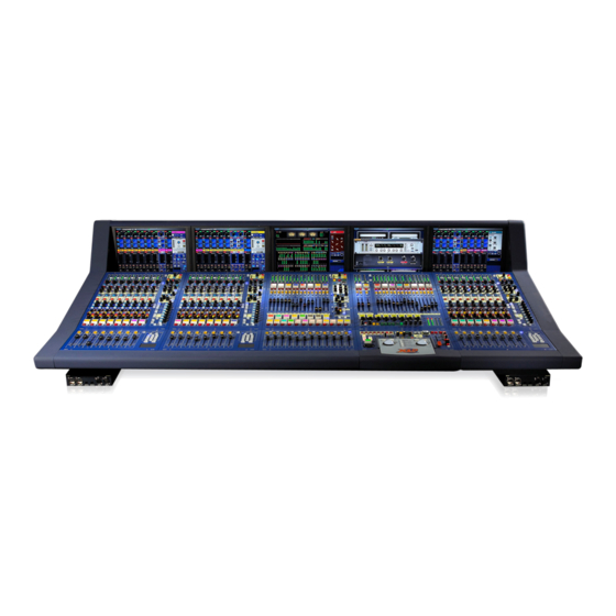
Chapter 1: Introduction The XL8 Control Centre is a user-friendly, state-of-the-art, high performance digital console that forms an integral part of the XL8 Live Performance System, which has been specifically designed for live use. The XL8 Control Centre comprises a combined control surface and graphical user interface (GUI) that provide an array of easy-to-use controls for precise manipulation of audio. -
Page 16: Xl8 Live Performance System Overview
AES50 digital audio, and uses readily available standard cabling and connectors. Along with the XL8 Control Centre, there are four mic splitters, five I/O units, 10 DSP units, two routers and a Klark Teknik DN9331 RAPIDE that, between them, form the standard XL8 Live Performance System configuration. -
Page 17: Bays
Bays Bays The XL8 control centre has five bays, of which there are three types: • Input Bays (3-off): Provide fast access to large numbers of faders and important input signal processing controls. The bays are numbered 1, 2 and 3, in order from left to right. -
Page 18: Control Surface Layout
- automation: scene store/recall and system edit. • - primary navigation zone: for mix bay and output bay GUI screen navigation via trackballs, and screen access panel for quick access to certain GUI screen menu options. XL8 Control Centre Quick Reference Guide... -
Page 19: Gui
The XL8 Control Centre has a graphical user interface (GUI) that provides a backdrop to the control surface. The GUI comprises five screens that have been manufactured to a high specification to give good definition in areas of strong light. This allows their displays to be clearly visible in sunlight, which makes the XL8 ideal for outdoor performances. -
Page 20: Output Bay Gui Display
Pull-out keyboard Front and rear connections Connector panels on the front and rear of the XL8 Control Centre provide XL8 Live Performance System interconnections that allow connection of peripheral devices, such as keyboards, monitors, portable PCs, USB memory keys etc. -
Page 21: Connections, Setting Up And Powering Up
Description of the XL8 connections Front and rear connector panels The XL8 has connector panels on the front and rear that house numerous types of connector, which cater for the connection of mains power leads, 19” rack units, USB memory keys, keyboards, headphones, talk mics, communications, external monitors (input and output), KVM (keyboard, video and mouse) switches, intercoms, AES3 synchronisation, word clocks (75R) and monitors. -
Page 22: Connecting Up The Xl8
Chapter 2: Connections, Setting Up And Powering Up Connecting up the XL8 This diagram shows the network interconnections for a typical FOH XL8 system. FOH XL8 Control Centre - rear Note: All connections are dual redundant, so the system can operate quite normally using either the X or Y cables. - Page 23 Connecting up the XL8 Note: FOH rack For connections specific to the 19” rack units, please refer to their respective operator manuals Control centre AES50 audio X connectors to FOH rack I/O unit AES50 audio X connectors Control centre AES50 audio Y connectors to...
-
Page 24: Cable Type And Function
Chapter 2: Connections, Setting Up And Powering Up Cable type and function Table 1 below shows the type, terminations and function of the XL8 system’s interconnecting cables. Please read the table in conjunction with the network interconnections diagram on page 8. -
Page 25: Manual Set-Up Of Unit Ids
Manual set-up of unit IDs Manual set-up of unit IDs After connecting up your XL8 network system, you may need to set up the ID of each mic splitter, I/O box and DSP unit connected in the XL8 system (although they are normally factory configured). -
Page 26: Powering The Xl8 System
After all XL8 system interconnections have been made, start up the XL8 system: Make sure that all of the XL8 system equipment is switched off, that is, the XL8 Control Centre, speaker sub-system, DL431 mic splitters, DL451 modular I/O units, DL461 routers and DL471 DSP units. -
Page 27: Switching The Xl8 Control Centre On/Off
Control centre will boot up (see “Booting up” on page 14); the GUI will display the default screens and all the controls will be set to default. You are now ready to start using the XL8 control centre. XL8 Control Centre... -
Page 28: To Switch Off The Xl8 Control Centre
Cold boot determines the system configuration and sets up all the IP addresses and unit names. Hot boot is the normal mode of operation (even if the XL8 has just been loaded from a truck and is physically cold!). Hot boot uses the configuration and names stored in the system flash memory. -
Page 29: Getting Started
Chapter 3: Getting Started This section is intended as a quick guide to familiarise you with the controls of the XL8 Control Centre and to show you how to carry out basic operations to enable you to get some audio out of it. -
Page 30: Working With The Controls
On the glide pad, you can also select by quickly double-tapping on the pad itself instead of using the select button, which may be more convenient as you only need to use one finger to complete the task. XL8 Control Centre Quick Reference Guide... -
Page 31: Navigating The Inputs
GUI in ascending order from left to right, irrespective of bay position. To help you understand the operating principles of the XL8 it may be best to visualise the control surface as if it were an analogue one, that is, in two dimensions with all 96 input channels laid out side by side. -
Page 32: To Select A Bank Of Input Channels
25-32 33-40 41-48 Input bay 2 Display changes to bank 33-40 33-40 41-48 49-56 Bank 41-48 is displayed on input bay 2’s GUI screen 41-48 49-56 57-64 Display changes to bank 49-56 XL8 Control Centre Quick Reference Guide... -
Page 33: To Select An Input Channel By Typing In Its Number
33-40 41-48 This shows the bank containing channels 33-40 selected to input bay 2 (default configuration) Type the required channel number, for example, “5”. Press ENTER. Illuminated LED bank indicator will change position accordingly. XL8 Control Centre Quick Reference Guide... -
Page 34: Setting A Mic Amplifier's Input Gain
Setting a mic amplifier’s input gain The XL8 Control Centre has two input gains per channel, one is the remote gain for the DL431 mic box (stage box gain) and the other is the digital trim (console gain). All of the input gain sections (control surface and input GUI screen) are interchangeable so that you can swap control from stage box gain to console gain, and vice versa. -
Page 35: Setting The High And Low Pass Filters
Stage box hi pass: The remote stage box contains a 12dB/Oct 30Hz filter. It is recommended that this is used at all times for optimum A/D performance. However, it may be bypassed if extremely low frequency performance is required, for example, when testing the system. XL8 Control Centre Quick Reference Guide... -
Page 36: Input Equalisation (E Zone)
SHAPE button (or by pressing MODE on the GUI channel strip). These filters are only available for treble (bright, classic and soft) and bass (deep, classic and warm). Note: “Bright” and “Deep” use psychoacoustic phenomena to generate steep slopes that sound natural. These filters are called “minimum harmonic disruption filters”. XL8 Control Centre Quick Reference Guide... -
Page 37: Input Dynamics Processing (D Zone)
(greater than 5:1). Audition different algorithms (hard knee, medium knee and soft knee) using the KNEE button. Try different compressor types (corrective, adaptive, creative and vintage) using the MODE button. XL8 Control Centre Quick Reference Guide... -
Page 38: To Set Up A Gate
In the required input fast strip, press ON to switch the gate on. Press the quick access button in the gate section to select the gate section. Apply processing by using the controls in D-zone, such as, attack, release, threshold, ratio/range and hold. XL8 Control Centre Quick Reference Guide... -
Page 39: Vca/Pop Groups
Release the VCA group select button. The VCA group now contains the input channel members you have just selected. To recall the VCA group, see “To recall a VCA/POP input group” on page 27. Input channel select buttons XL8 Control Centre Quick Reference Guide... -
Page 40: To Set Up The Name And Colour Of A Vca/Pop Group
Assign a backlight colour to the VCA group select button and background of name field on GUI by: a) Clicking on the palette icon. b) Clicking on your chosen colour to select it, for example, blue. XL8 Control Centre Quick Reference Guide... -
Page 41: To Recall A Vca/Pop Input Group
If any of these LEDs flash, it means there are current VCA/POP group members within the respective bank(s) that are not selected to the control surface. XL8 Control Centre Quick Reference Guide... -
Page 42: Navigating The Outputs
To select a bank of returns or auxes to the mix bay control surface, press RET or AUX as required. Pressing a bank select button selects that bank to the control surface. This is confirmed by its associated LED in the detail active section being illuminated. XL8 Control Centre Quick Reference Guide... -
Page 43: To Select An Output Channel
2 aux 1 Scrolls left by one channel Scrolls right by one channel Only one of these LEDs will be highlighted to show which bank is currently selected to the control surface XL8 Control Centre Quick Reference Guide... -
Page 44: Setting Up A Mix
Chapter 3: Getting Started Setting up a mix XL8 has 32 configurable mix buses, each of which can be aux mixes, subgroups and mix minus. The aux mixes can also be set up as stereo pairs or mono. 16 matrix outputs can also be accessed directly from input channels via level controls, which gives the XL8 the ability to provide 48 discrete mixes, plus left, right and mono. - Page 45 Level indicators are bright on selected channel but dimmed on inactive/muted channels This transition point, where solid colours change to translucent, indicates 0dB across the eight auxes Matrix mix Aux mix XL8 Control Centre Quick Reference Guide...
-
Page 46: To Program A Mix Preset
While still holding down the set upper button, repeat steps 1 and 3 for all other odd numbered mixes you with to select to the preset. Release set upper button. Presets are stored. XL8 Control Centre Quick Reference Guide... -
Page 47: Setting Up The Effects Rack
In “Select Device Type” window, click on one of the changes by clicking on “X” at top right-hand corner of available device types, for example, “Phaser”. (The device window. effects in the list may be slightly different on your display, XL8 Control Centre Quick Reference Guide... -
Page 48: Routing An Aux To An Effect Or Output
Click on the name of the output source you require, for example, the effect you have just set up in “Setting up the effects rack” on page 33. XL8 Control Centre Quick Reference Guide... -
Page 49: Simple Routing To Master Stereo Outputs
To obtain audio, simply press the ST (stereo) button of an input fast strip in an input fast zone or in the output channel strip. Then, while making sure nothing is muted and master faders are up, you will have audio. XL8 Control Centre Quick Reference Guide... -
Page 50: Scenes (Automation)
Click OK; control surface settings revert to default. You can now create and manage the scenes for your new show. Don’t forget to save at regular intervals. XL8 Control Centre Quick Reference Guide... -
Page 51: To Save A Show
Scenes (automation) To save a show The XL8 will indicate to you when there are show settings to be saved. It does this by changing the background colour of the SAVE button to red, as shown below. To save, simply click on the SAVE button. We recommend you save your show settings regularly. -
Page 52: To Store A Scene
“Store to empty scene” “Store to next scene” “Overwrite scene” You can use the keyboard to type in any useful scene information in the “Scene Notes” window, if you wish. Click OK to save the scene. XL8 Control Centre Quick Reference Guide... -
Page 53: To Recall A Scene
When you reach the end of the cue list, it just wraps around to the beginning so you can continue from the start again. XL8 Control Centre Quick Reference Guide... -
Page 54: Naming Inputs And Outputs
From here, set up the output name and colour; see “To set up This button takes you to the output channels the name and colour of a VCA/POP group” on page 26. screen; see page 28 for an example XL8 Control Centre Quick Reference Guide... -
Page 55: Areas A And B (Split Surface/Dual Operation)
Areas A and B can now be used independently of each other. A typical configuration for area A and B operation is shown below, although any input bay can be used as area B. Area A Area B XL8 Control Centre Quick Reference Guide... -
Page 56: Saving Your Show Files To Usb Memory Stick
USB memory stick. This provides a valuable back up should the one stored in the XL8 be lost, for example, due to inadvertent deletion or in the highly unlikely event of system failure. -
Page 57: Troubleshooting
1. The current method of resetting the master controllers involves the use of the reset buttons on the control surface. In future XL8 versions this procedure will be under software control and will be carried out via the GUI’s Diagnostics screen. - Page 58 Chapter 3: Getting Started XL8 Control Centre Quick Reference Guide...
- Page 59 Thank you for reading through this Quick Reference Guide. We hope you found it useful. Please feel free to send us your comments. More detailed information on the XL8 can be found in the XL8 Control Centre Operator Manual, part number DOC02-XL8. This is available for download from our website.
- Page 60 Midas Klark Teknik Building, Walter Nash Road, Kidderminster. Worcestershire. DY11 7HJ. England. Tel: +44 1562 741515, Fax: +44 1562 745371 Email: info@uk.telex.com Website: www.midasconsoles.com...
Need help?
Do you have a question about the XL8 and is the answer not in the manual?
Questions and answers