Table of Contents
Advertisement
Quick Links
DL461 Router
Operator Manual
Midas Klark Teknik Limited,
Klark Industrial Park,
Walter Nash Road,
Kidderminster.
Worcestershire.
DY11 7HJ.
England.
Tel: +44 1562 741515
Fax: +44 1562 745371
Email: info@midasklarkteknik.com
Website: www.midasconsoles.com
DL461 Router — Operator Manual
DOC02-DL461 Issue B — April 2010
© Red Chip Company Ltd.
In line with the company's policy of continual improvement, specifications and function may be
subject to change without notice. This document was correct at the time of writing. E&OE.
Advertisement
Table of Contents

Related Manuals for Midas XL8 DL461


Summary of Contents for Midas XL8 DL461
- Page 1 DL461 Router Operator Manual Midas Klark Teknik Limited, Klark Industrial Park, Walter Nash Road, Kidderminster. Worcestershire. DY11 7HJ. England. Tel: +44 1562 741515 Fax: +44 1562 745371 Email: info@midasklarkteknik.com Website: www.midasconsoles.com DL461 Router — Operator Manual DOC02-DL461 Issue B — April 2010 ©...
-
Page 3: Important Safety Instructions
IMPORTANT SAFETY INSTRUCTIONS The lightning flash with arrowhead symbol within an equilateral triangle is intended to alert the user to the presence of uninsulated “dangerous voltage” within the product's enclosure that may be of sufficient magnitude to constitute a risk of electric shock to persons. The exclamation point within an equilateral triangle is intended to alert the user to the presence of important operating and maintenance (servicing) instructions in the literature accompanying the product. -
Page 5: Ec-Declaration Of Conformity
Midas EC-Declaration of Conformity The undersigned, representing the following manufacturer Manufacturer: Address: Midas Klark Teknik Ltd. Klark Industrial Park, Walter Nash Road, Kidderminster. Worcestershire. DY11 7HJ. hereby declares that the following product Product Type Number Product Description Nominal Voltage(s) Current Freq. -
Page 7: Licences
Licences The following are the license agreements applicable to the Midas Digital Equipment. End-User Licence Agreement for Midas™ and Klark Teknik™ Software IMPORTANT - Please read this document carefully before using this Midas™ or Klark Teknik™ Product. This is an agreement governing your use of software or other machine instructions already installed on this Midas™... - Page 8 DATE INFORMATION. You understand that the Company may update or revise the Software but in so doing incurs no obligation to furnish such updates to you. However, the Company may in its discretion make updates available from time to time upon such terms and conditions as it shall determine.
- Page 9 and the Courts of England and Wales will have exclusive jurisdiction to hear and decide any dispute concerning it or its formation. No breach by you of any provision of this Licence shall be waived or discharged except with the express written consent of the Company and no failure or delay by the Company to exercise any of its rights under this Licence shall operate as a waiver thereof and no single or partial exercise of any such right shall prevent any other or further exercise of that or any other right.
-
Page 11: Precautions
Precautions Before installing, setting up or operating this equipment, make sure that you have read and fully understand all of this section and the “IMPORTANT SAFETY INSTRUCTIONS” at the front of this manual. This equipment is supplied by a mains voltage that can cause electric shock injury! The following must be observed in order to maintain safety and electromagnetic compatibility (EMC) performance. -
Page 12: Optional Equipment
Precautions • Power plug must be inserted in a socket communications. Operation of this equipment outlet provided with a protective earth in a residential area is likely to cause harmful contact. The electrical supply at the socket interference in which case the user will be outlet must provide appropriate required to correct the interference at his own over-current protection. -
Page 13: Table Of Contents
Contents Information page ......... . . i IMPORTANT SAFETY INSTRUCTIONS . - Page 14 Contents Appendix A Technical Specification ..... . . 15 General specifications ........15 XL8 system inputs and outputs .
-
Page 15: Chapter 1: Introduction
Chapter 1: Introduction The DL461 Router is a three-unit (3U) high 19” rack unit that provides the on-stage interconnectivity and stage-to-FOH link via a single Cat6 cable (up to 100 metres long) or fibre optic link (up to 500 metres long). The DL461 Router, which forms the heart of the XL8 digital audio transport network, features 20 AES50 connections, work clock, AES3 interfaces and Ethernet message tunnelling for third party systems. -
Page 16: Warranty And Registration
Chapter 1: Introduction Warranty and registration Midas has total confidence in the quality and reliability of this product. To back this up, this product comes with the standard Midas and Klark Teknik three year warranty. Please take the time to register your product by completing and returning the registration card or registering on our website at www.midasconsoles.com. -
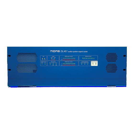
Page 17: Chapter 2: Front Panel
Chapter 2: Front Panel The front panel of the DL461 Router comprises the following: Item Description psu monitoring panel (see “psu panel” below). snake monitoring panel (see “snake panel” on page 4). AES50 audio - bank 0 digital link monitoring panel (see “AES50 audio - bank panels”... -
Page 18: Snake Panel
Chapter 2: Front Panel snake panel The snake panel monitors the communications on the optical and Cat6e cabling. Each cable type has an ok and an error LED. The ok LED pulsates when the link is synchronised between the router and end point. The error LED illuminates when either no communications or a fault are detected. -
Page 19: Ethernet Tunnel Panel
Ethernet tunnel panel Ethernet tunnel panel When illuminated, the green ext 1 and ext 2 LEDs in the Ethernet tunnel panel show that third party devices are connected to these ports. router select panel The white router select button (shown right) is used to select which of the XL8’s two internal 8-port routers the DL461 Router is connected to (X or Y). - Page 20 Chapter 2: Front Panel DL461 Router Operator Manual...
-
Page 21: Chapter 3: Rear Panel
Chapter 3: Rear Panel The rear panel comprises the following: • Two banks of AES50 EtherCon® XLR connectors. • One bank of EtherCon® XLR connectors for Ethernet control. • Input and output word clock connectors. • AES3 synchronisation XLR input and output connectors. •... -
Page 22: Rear Panel Connections
Chapter 3: Rear Panel Rear panel connections AES50 audio - Ethernet AES50 audio - bank 1 (1 - 10) control bank 0 (1 - 10) (1 - 10) Mains IEC connector Item Description AES50 audio - bank 0 and AES50 audio - bank 1: digital input EtherCon®... -
Page 23: Led Indicators
LED indicators Item Description word clock 75R input and output BNC cable sockets for connection of external synchronisation. Mains IEC socket with on/off switch. LED indicators Item Description Green and red LEDs for both banks (0 and 1) of the AES50 audio sockets indicate the following conditions: •... - Page 24 Chapter 3: Rear Panel DL461 Router Operator Manual...
-
Page 25: Chapter 4: Getting Started
Chapter 4: Getting Started This chapter shows you how to connect up, switch on, set up and configure the DL461 Router. Note: The DL461 Router is operated from the XL8 Control Centre only. For more information, see the XL8 Live Performance System Owner’s Manual (part number DOC02-XL8). - Page 26 Chapter 4: Getting Started Stage rack 2 X Router DSP 1 DSP 2 DSP 3 DSP 4 DSP 5 DSP 6 DSP 7 DSP 8 DSP 9 DSP 10 Y Router Stage rack 1 Router to DSP - Ethernet control connections Router to DSP - AES50 audio connections...
-
Page 27: Switching The Unit On/Off
Switching the unit on/off Switching the unit on/off After you have connected up your DL461 Router it is ready to be switched on. To do this, switch on the mains on/off switch on the rear panel. Check that both of the yellow LEDs in the psu panel are illuminated (see “psu panel”... - Page 28 Chapter 4: Getting Started DL461 Router Operator Manual...
-
Page 29: Appendix A Technical Specification
Appendix A: Technical Specification This appendix contains the technical specifications specific to the DL461 Router. For system related XL8 Control Centre specifications and for full technical specifications for the XL8 Live Performance System, see the Owner’s Manual (part number DOC02-XL8). Due to a policy of continual improvement, Midas reserves the right to alter the function or specification at any time without notice. -
Page 30: Miscellaneous Inputs And Outputs
Appendix A: Technical Specification Miscellaneous inputs and outputs Word clock IN connector Word clock OUT connector AES3 sync IN connector 3-pin XLR AES3 sync OUT connector 3-pin XLR Ethernet tunnel 1 connector EtherCon® XLR Ethernet tunnel 2 connector EtherCon® XLR Expansion Ethernet connector EtherCon®... -
Page 31: Appendix B Service Information
Appendix B: Service Information This appendix gives you servicing information for your unit. If you are in any doubt or have queries about any of the procedures in this appendix, contact Midas Technical Support. Contact details can be found at the front of this manual. -
Page 32: Equipment Disposal
Appendix B: Service Information Equipment disposal When this equipment has come to the end of it useful life, its disposal may come under the DIRECTIVE 2002/96/EC OF THE EUROPEAN PARLIAMENT AND OF THE COUNCIL of 27 January 2003 on waste electrical and electronic equipment (WEEE). Hazardous substances in WEEE contaminate water, soil and air and ultimately put at risk our environment and health. -
Page 33: Appendix Cxl8 Live Performance System
Appendix C: XL8 Live Performance System The XL8 Live Performance System is a very powerful and flexible audio processing system that provides a complete solution for any audio mixing and signal distribution application in a live sound environment. The standard XL8 system offers 96 channel inputs, 51 outputs, 51 buses (32 auxes/groups, 16 matrices and three masters), 16 on-board effects processors, PEQs (four-band on inputs and six-band on outputs), up to 48 assignable GEQs (if all stereo effects units are being used), 16 configurable stereo effects (from eight options),... - Page 34 Appendix C: XL8 Live Performance System Configuration • All outputs have six-band parametric EQ and five-mode compressor styles. • Up to 16 stereo FX units. • Up to 48 assignable GEQs (16 if all 16 stereo FX units are being used). •...
- Page 35 Features User interface - status visibility • Daylight-visible screens. • Metering. • 63 discrete 20-segment LED meters. • Discrete metering for dynamics and direct outputs. • “All the meters all of the time”. • “ST” assign switch. • Eight channels of key data plus single channel strip per input screen. Dual operators - perfect for festival situations •...
-
Page 36: System Components (Standard Supply)
Appendix C: XL8 Live Performance System System components (standard supply) The standard XL8 Live Performance System comprises the following equipment: • XL8 Control Centre (1-off): Comprises five discrete, independent bays, each with its own power supply, surface modules, surface processor, GUI processor and GUI screen. -
Page 37: System Interconnections
System interconnections System interconnections Figure 1 shows basic system interconnectivity and indicates where the XL8 Control Centre (highlighted in red) sits within the system. This figure also illustrates redundancy by showing that the two halves of the system - left and right - are identical (ignoring the DN9331 RAPIDE). -
Page 38: Foh And Mon
Appendix C: XL8 Live Performance System FOH and MON The XL8 Live Performance System can be used as a front of house (FOH) or stage monitor (MON) system. Also, by sharing the four mic splitters, these two types of system can be used in tandem, as shown in Figure 2 on page 24. Figure 4 on page 31 shows in more detail the interconnections between each unit in a typical XL8 Live Performance System FOH and MON set up. -
Page 39: Mix Matrix
Mix matrix Mix matrix Ultimately, the mix matrix defines the XL8 Control Centre’s capability. Probably the best way to imagine the mix matrix is to think of an analogue console layout, where inputs run vertically and buses run horizontally. A mix matrix is usually defined as the number of buses and the quantity of simultaneously-mixable inputs there are per bus. -
Page 40: Mix Channel Processing
Appendix C: XL8 Live Performance System Each of the 16 auxiliary inputs has: • Input gain. • Source from internal FX or external pool input. • Fader. • Panpot (SIS™). • Routing via level controls to the 16 matrix buses. •... -
Page 41: Effects Processing And Geqs
Audio physical connections Effects processing and GEQs The XL8 contains 16 mono Klark Teknik (KT) GEQs and 16 effects processors as standard. The 16 effects processors can be freely chosen from: • Delay. • KT DN780 reverb. • Flanger. • Phaser. •... -
Page 42: Uses Of The Configurable Audio Connections
Appendix C: XL8 Live Performance System Uses of the configurable audio connections The standard XL8 Live Performance System has a total configurable audio channel count (on the DL451 I/O units) of between 120 and 240, depending on the mix of analogue and digital I/O (excluding the non-configurable 96 mic inputs on the DL431 mic splitter). -
Page 43: Surround Capabilities
Surround capabilities The maximum count of any one type of connection is: • 96-off input insert sends. • 96-off input insert returns. • 96-off input compressor external side chain connections. • 96-off input noise gate external side chain connections. • 96-off input direct outputs. •... -
Page 44: Resilience To Failure (Redundancy)
Appendix C: XL8 Live Performance System All system connections are duplicated for full dual redundancy. Resilience to failure (redundancy) The XL8 Live Performance System is tolerant of any single failure of hardware or software. To achieve this the system employs dual-redundancy, where a key component has an identical redundant spare that is ready to take over should it fail. - Page 45 Resilience to failure (redundancy) Local I/O units Internal bay processor Dual redundant XL8 Control Centre internal master controller Dual redundant internal router Control data Cat6/optical ‘snake’ Audio data N + 1 redundant Control and spare audio data Router Clock sync Monitor This diagram gives a more detailed...
- Page 46 Appendix C: XL8 Live Performance System Local I/O units XL8 Control Centre Not active Internal bay processor Internal master controller Internal router units I/O units Router This diagram illustrates an extreme Monitor example of dual redundancy in a standard FOH and stage monitor set up, splitters where one half of the...
- Page 47 Resilience to failure (redundancy) Local I/O units Not active Internal bay processor Internal master controller XL8 Control Centre Internal router units I/O units Router Router (healthy) (faulty) Monitor This diagram illustrates the effects of a single router splitters failure in an FOH and (shared) stage monitor set up.
-
Page 48: Control Software
Appendix C: XL8 Live Performance System Control software The XL8’s operating system is Linux, which is an open-source, stable, proven operating system (OS). Linux is used in many mission-critical applications worldwide and has allowed Midas’ software engineers to write a ground-up system that contains no ‘hidden’... - Page 49 Integration of third party software The XL8 Control Centre features a four-way KVM switch on the output module screen, as well as external video IN and OUT for each of the five screens. Control centre views can be routed to external monitors, and external video sources can be displayed on the control centre’s screens.
- Page 50 Appendix C: XL8 Live Performance System DL461 Router Operator Manual...
-
Page 51: Appendix D Setting Up An Xl8 System
Appendix D: Setting Up An XL8 System This chapter shows you how to set up an XL8 Live Performance System to its default configuration. Note: If you want to set up the XL8 Live Performance System using a configuration other than the default, please contact Midas Technical Support for details. Initial set-up procedure Initial system set-up basically comprises: •... -
Page 52: Outboard Equipment Racks
Appendix D: Setting Up An XL8 System Outboard equipment racks To ensure the correct installation and function of the outboard equipment, such as the DL4n1 units and DN9696 recorder, the racks must meet the following general requirements. • Shock mounting (for non-installation environments): The racks must provide adequate shock protection of the units they house by incorporating appropriately- designed shock protection methods, for example, a foam-suspended rack or a frame suspended on anti-vibration mounts etc. -
Page 53: Stage Rack 2
Wiring instructions Stage rack 2 Stage rack 2, also known as the “DL461/DL471 engine rack”, contains the two routers and 10 DSP units. Important: In general, the physical location of the hardware units within each rack is not critical, and alternative configurations are acceptable for different packaging preferences. - Page 54 Appendix D: Setting Up An XL8 System >> To connect the routers to the Stage rack 3 units • Mic splitters: In AES50 audio - bank 1 on the X router, connect sockets 3 and 4 to the AES50 audio - A X sockets on the mic splitters. Repeat for the Y router, using the mic splitters’...
- Page 55 Wiring instructions 0.25 m cable option 0.5 m cable option Stage rack 2 AMU 1 AMU 1 AMU 2 AMU 2 AMU 3 AMU 3 AMU 4 AMU 4 AMU 5 AMU 5 AMU 6 AMU 6 AMU 7 AMU 7 AMU 8 AMU 8 AMU 9...
-
Page 56: Xl8 System Interconnections
Appendix D: Setting Up An XL8 System XL8 system interconnections This diagram shows the network interconnections for a typical FOH XL8 system. Rear of FOH XL8 Control Centre RAPIDE Connect to both X and Y networks Note: All connections are dual redundant, so the system can operate quite normally using either the X or Y cables. - Page 57 XL8 system interconnections FOH rack Note: For connections specific to the 19” rack units, please refer to their respective operator manuals ID: 1 Config: I/O/D IP: 192.168.36.1 ID: 2 Caution! Config: I/O/D Don’t forget the IP: 192.168.36.2 interconnection between the two routers, as system snake redundancy will be compromised without it.
-
Page 58: Cable Type And Function
Appendix D: Setting Up An XL8 System Cable type and function The following table shows the type, terminations and function of the XL8 system’s interconnecting cables. Please read the table in conjunction with the network interconnections diagram on page 42. Cable From Description... -
Page 59: Powering The Xl8 System
Powering the XL8 system Powering the XL8 system The following details the recommended power up and power down procedures for the XL8 system. >> To power up the XL8 system Important Note: DO NOT switch on the speaker sub-system until after the start-up of the XL8 system has been completed. -
Page 60: Switching The Xl8 Control Centre On/Off
Appendix D: Setting Up An XL8 System Switching the XL8 Control Centre on/off Carry out the following to switch the XL8 Control Centre on/off in a safe manner, observing all WARNINGS and Cautions. >> To switch on the XL8 Control Centre WARNING! DO NOT INSERT OR REMOVE A POWERCON®... -
Page 61: Setting Up The Id Of The Dl4N1 Units
Setting up the ID of the DL4n1 units >> To switch off the XL8 Control Centre Make sure you have saved any shows, scenes or settings you require (see “Saving your show files to a USB memory stick” on page 56). At the GUI, choose home Preferences Shutdown System. - Page 62 Appendix D: Setting Up An XL8 System DL461 Router Operator Manual...
- Page 63 Thank you for reading through this Operator Manual. We hope you found it useful. Please feel free to send us your comments. More detailed information on the XL8 can be found in the XL8 Live Performance System Owner’s Manual (part number DOC02-XL8). This is available for download from our website.
- Page 64 Midas Klark Teknik Limited Klark Industrial Park, Walter Nash Road, Kidderminster. Worcestershire. DY11 7HJ. England. Tel: +44 1562 741515, Fax: +44 1562 745371 Email: info@midasklarkteknik.com Website: www.midasconsoles.com...
Need help?
Do you have a question about the XL8 DL461 and is the answer not in the manual?
Questions and answers