Table of Contents
Advertisement
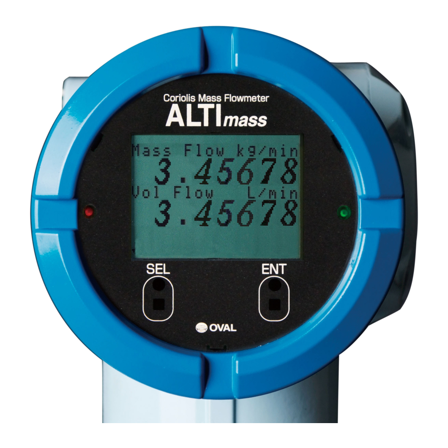
ALTI
■ Type U/Sophisticated models: CA00A, CA001, CA003, CA006, CA010, CA015
■ Type S/Straight tube models: CS010, CS015, CS025, CS040, CS050, CS080
■ Type B/Low price, general purpose models:
■ Transmitter
Type U
Type U
Extra low flows
Every OVAL product is fabricated, tested, and inspected under stringent quality control before it
leaves our factory.
To derive maximum benefit from the product, we recommend you to be well familiar with the
information and instructions given in this manual before you place it in service and retain this
manual at the field location for ready reference.
mass
CA025, CA040, CA050, CA080, CA100, CA150
CA15H, CA200, CA20H, CA250
CSR50
CB006, CB010, CB015, CB025, CB040, CB050
: PA0K
Type S
Type U
Low flows
Ins. No. L-740-28-E
Type U
Separately mounted
Large size
Type B
transmitter
1
Advertisement
Table of Contents

Related Manuals for Oval ALTI mass CA00A


Summary of Contents for Oval ALTI mass CA00A
- Page 1 Low flows Large size transmitter Every OVAL product is fabricated, tested, and inspected under stringent quality control before it leaves our factory. To derive maximum benefit from the product, we recommend you to be well familiar with the information and instructions given in this manual before you place it in service and retain this...
-
Page 2: Table Of Contents
L -- 740 -- 28 -- E CONTENTS ......................5 1. BEFORE YOU BEGIN 1.1 Confirming the Tag Information ..................... 5 1.2 Transportation Guidelines ..................... 5 1.3 Storage Guidelines ........................ 5 1.4 Precautions for Operating Conditions ................... 6 1.5 Precautions for Installation Location ..................6 1.6 Precautions for power-on ...................... - Page 3 L -- 740 -- 28 -- E 6.8 A Boss for Pressure Relief Device - Its Use ............... 52 6.9 Separately Mounted Transmitter Installation ................. 52 6.10 How to Change Transmitter Orientation ................52 6.11 How to Change Transmitter Display Orientation..............54 ......................
- Page 4 L -- 740 -- 28 -- E 9.14.4 Drive output alarm (Used for maintenance purpose)........... 106 9.14.5 No assignment (No Function) ..................106 9.15 Status Input Function ......................107 9.15.1 Pulse/analog output fixed at 0% (0% Sig Lock) ............107 9.15.2 Zero adjustment (Auto Zero) ..................
-
Page 5: Before You Begin
For any inquiries, call the sales office from which you purchased the product, or contact the nearest OVAL representative in our customer service network. 1.1 Confirming the Tag Information Product code and major ratings appear on the nameplate attached on the side of transmitter. Make sure that the product you received complies with the specifications in your order. -
Page 6: Precautions For Operating Conditions
20 minutes after powering-on. The number indicates remaining warm-up period (min.). 1.7 Returning Equipment If the meter must be returned to OVAL for any reason, follow these steps to ensure the most efficient processing. (1) Clean the unit and flush out the tubes without fail and pack the sensor unit carefully. Fully document the fluid. -
Page 7: General And Features
※7: This pressure does not represent the rated test pressure of a pressure vessel, but 1/4 of the breakdown test pressure at OVAL (distorted enclosures do not constitute a failure of the test), or the data obtained from the FEM analysis, whichever is lower (or safer). - Page 8 ※8: This pressure does not represent the rated test pressure of a pressure vessel, but 1/4 of the breakdown test pressure at OVAL (distorted enclosures do not constitute a failure of the test), or the data obtained from the FEM analysis, whichever is lower (or safer).
- Page 9 ※6: This pressure does not represent the rated test pressure of a pressure vessel, but 1/4 of the breakdown test pressure at OVAL (distorted enclosures do not constitute a failure of the test), or the data obtained from the FEM analysis, whichever is lower (or safer).
- Page 10 ※3: This pressure does not represent the rated test pressure of a pressure vessel, but 1/4 of the breakdown test pressure at OVAL (distorted enclosures do not constitute a failure of the test), or the data obtained from the FEM analysis, whichever is lower (or safer).
-
Page 11: Type S Sensor Unit General Specifications
※3: CIP/SIP procedures must be performed within the heatproof temperature range. ※: Temperature class for integral type is T4. ※: For products that are compliant with the High Pressure Gas Safety Act, consult OVAL. Titanium tube type (CS010 to CSR50) ●... -
Page 12: Transmitter General Specifications
L -- 740 -- 28 -- E 3.1.4 Transmitter general specifications Item Description Model PA0K Power source 85 to 264VAC, 50 / 60Hz (Safety rated 100 to 240VAC 50/60Hz) or 20 to 30VDC Power consumption 15W max. - Ambient temperature 40 to +55°... -
Page 13: General Performance
L -- 740 -- 28 -- E 3.2 General Performance Zero stability Zero stability error = ×100% Flowrate at the time of testing ※: Measurement unit of zero stability and flowrate at the time of testing must be the same. 3.2.1 Type U general performance Standard (CA00A, CA001 and CA003) ●... - Page 14 ※2: ±1/2 Zero stability error is applied for flow rates below 5% of the max. service rate. (within guaranteed flow range) ※3: If higher accuracy (±0.1% of reading) is required, consult OVAL. ※: The general performance is based on factory calibration accuracy.
- Page 15 L -- 740 -- 28 -- E High temperature service models (CA025 to CA080) ● Item Description CA025 CA040 CA050 CA080 Model (High temp. service) (High temp. service) (High temp. service) (High temp. service) Guar. min. meas. rate 1200 (kg/h) Min.
-
Page 16: Type S General Performance
L -- 740 -- 28 -- E 3.2.2 Type S general performance Stainless steel tube type (CS010 to CS080) ● Item Description Model CS010 CS015 CS025 CS040 CS050 CS080 Guar. min. meas. rate (kg/h) 1800 3600 Min. setting rate (kg/h) 1800 3600 7200... -
Page 17: Display
L -- 740 -- 28 -- E 3.3 Display Display modes ①Mass instant flowrate ②Volume instant flowrate ③Density ④Temperature ⑤Pulse count 1 (mass or volume) ⑥Pulse count 2 (mass or volume) ⑦Total 1 (mass or volume) ⑧Total 2 (mass or volume) ⑨Analog 1 (% instant) ⑩Analog 2 (% instant) ⑪Status information... - Page 18 10 0 mPa・s 0.01 0.01 10 0 mPa・s 10 mPa・s 0.001 0.001 10 mPa・s L -- 740 -- 28 -- E 1mPa・s 0.0001 0.0001 1mPa・s 0.00001 0.00001 0. 01mPa・s 0. 01mPa・s 0.000001 0.000001 1000 1000 Flowrate (kg/h) Flowrate (kg/h) CA010 CA015 CA015 1000mPa・s 1000mPa・s 0.01...
-
Page 19: Type S Pressure Losses
L -- 740 -- 28 -- E 4.2 Type S Pressure Losses CS010 CS015 5 0 0 mPa・s 2 0 0 mPa・s 10 0 mPa・s 5 0 0 mPa・s 2 0 0 mPa・s 10 0 mPa・s 5 0 mPa・s 0.01 0.01 5 0 mPa・s 10 mPa・s... -
Page 20: Type B Pressure Losses
Specific gravity of high-viscosity liquid (1 for water) C: Pressure loss coefficient found from the maximum ※1: Pressure loss is calculated with Newtonian fluid. viscosity curve at a given flowrate For Non-Newtonian fluid, please consult OVAL. (g/min. or kg/h) -
Page 21: Part Names And Outline Dimensions
L -- 740 -- 28 -- E 5. PART NAMES AND OUTLINE DIMENSIONS 5.1 Type U 5.1.1 CA00A, CA001 and CA003 (separately mounted models) Dimensions in millimeters Ground screw Terminal box Flow direction R1/4 Process connection Flow direction arrow Cable entry G3/4 Main body (G1/2 : TIIS) 4-φ9 Fitting hole (Fits M8 bolt.) Cable entry G 3/4 Fig. -
Page 22: Ca006 Thru Ca080 (Integrally Mounted Models)
L -- 740 -- 28 -- E 5.1.2 CA006 thru CA080 (integrally mounted models) Cable entry G3/4 Flow direction Ground screw Dimensions in millimeters Flange App. Weight Model Nom. size Flange rating kg (JIS 10K) JIS 10K JIS 20K JIS 30K JIS 40K JIS 63K CA006 ASME, JPI 150... - Page 23 L -- 740 -- 28 -- E Screw-in type Screw conn. App. Weight Model (kg) Connection CA006 Rc3/8 CA010 Rc3/8 CA015 Rc3/4 Dimensions in millimeters Flange App. Weight Model kg (JIS 10K) Nom. size Flange rating JIS 10K JIS 20K JIS 30K JIS 40K JIS 63K...
-
Page 24: Ca100 Thru Ca250 (Integrally Mounted Models)
L -- 740 -- 28 -- E 5.1.3 CA100 thru CA250 (integrally mounted models) 64 127 Cable entry Cable entry Ground screw G3/4 G3/4 Ground screw Ground screw Flow direction Flow direction Flange Flange Boss Boss Rc1/4 Rc1/4 (CA100 and 150) (CA15H to 250) Dimensions in millimeters Flange App. -
Page 25: Ca006 Thru Ca080 (Separately Mounted Models)
L -- 740 -- 28 -- E 5.1.4 CA006 thru CA080 (separately mounted models) Terminal box φ107 Cable entry G3/4 (G1/2 : TIIS) Flow direction Flange Ground screw Dimensions in millimeters Flange App. Weight Model kg (JIS10K) Nom. size Flange rating JIS 10K JIS 20K JIS 30K JIS 40K JIS 63K CA006... - Page 26 L -- 740 -- 28 -- E Screw-in Type Screw conn. App. Weight Model (kg) Connection CA006 Rc3/8 CA010 Rc3/8 CA015 Rc3/4 Dimensions in millimeters Flange App. Weight Model kg (JIS10K) Nom. size Flange rating JIS 10K JIS 20K JIS 30K JIS 40K JIS 63K CA025...
-
Page 27: Ca100 Thru Ca250 (Separately Mounted Models)
L -- 740 -- 28 -- E 5.1.5 CA100 thru CA250 (separately mounted models) Terminal box Ground Ground screw screw Cable entry G3/4 Ground screw (G1/2:TIIS) Flow direction Flow direction Flange Flange Boss Boss Rc1/4 Rc1/4 (CA100 and 150) (CA15H to 250) Dimensions in millimeters Flange App. Weight Model kg (JIS10K)... -
Page 28: High Temperature Service Models (Ca025 To Ca150)
L -- 740 -- 28 -- E 5.1.6 High temperature service models (CA025 to CA150) Transmitter separately mounted type/Flange connection type (CA0250, CA040, CA050, CA080) φ107 Terminal box Cable entry G3/4 Heat retention fluid inlet (G1/2 : TIIS) Heat retention fluid outlet φ10 stainless steel pipe φ10 stainless steel pipe Flow Flow direction direction For holding heat tracer M6 bolt Ground screw... -
Page 29: Low Temperature Explosionproof Service Models (Ca025 To Ca080)
L -- 740 -- 28 -- E 5.1.7 Low temperature explosionproof service models (CA025 to CA080) φ107 Terminal box Cable entry G3/4 (G1/2 : TIIS) Flow direction Flange Ground screw Dimensions in millimeters Flange App. Weight Model kg ( JIS 10K) Nom. size Flange rating JIS 10K JIS 20K JIS 30K CA025... -
Page 30: Low Temperature Explosionproof Service Models (Ca100 To Ca250)
L -- 740 -- 28 -- E 5.1.8 Low temperature explosionproof service models (CA100 to CA250) φ107 Terminal box Ground Ground Ground screw Cable entry G3/4 screw screw (G1/2 : TIIS) Flow Flow direction direction Flange Flange Boss Boss Rc1/4 Rc1/4 (CA100 and 150) (CA15H to 250) Dimensions in millimeters Flange... -
Page 31: Ferrule Fitting Type
L -- 740 -- 28 -- E 5.1.9 Ferrule fitting type (integrally and separately mounted models, low temp. explosionproof service models) Integrally mounted type ● Cable entry G3/4 Flow direction Ferrule Ground screw Dimensions in millimeters Ferrule fitting App. Weight Model φD Nom. size Connection CA006 Ferrule 10A... - Page 32 L -- 740 -- 28 -- E Separately mounted type ● Cable entry G 3/4 φ107 Terminal box (G1/2:TIIS) φ107 Cable entry G3/4 (G1/2 : TIIS) Flow direction Ferrule Ground screw Ground screw Dimensions in millimeters Ferrule fitting App. Weight Model φD Nom. size Connection CA003 Ferrule 10A 89.1 CA006 Ferrule 10A 231.5...
-
Page 33: Type S
L -- 740 -- 28 -- E 5.2 Type S 5.2.1 Stainless steel tube type (integrally and separately mounted models) Integrally mounted models ● Cable entry G3/4 Flow direction φF φG Dimensions in millimeters Nom. App. Weight ASME/JPI Model φF φG size kg (JIS 10K) CS010 15 (... -
Page 34: Low Temperature Explosionproof Service Models)
L -- 740 -- 28 -- E 5.2.2 Titanium tube type (integrally and separately mounted models) Integrally mounted models ● Cable entry G3/4 Flow direction φF φG Dimensions in millimeters App. Weight Nom. ASME/JPI φF φG Model size Cable entry (JIS 10K) G3/4 φ107 CS010 10(1/2")... -
Page 35: Ferrule Fitting Type (Integrally And Separately Mounted Models)
L -- 740 -- 28 -- E 5.2.3 Ferrule fitting type (integrally and separately mounted models) Integrally mounted type ● Cable entry G3/4 Ferrule fitting Flow direction Dimensions in millimeters Model Nom.size φD App. Weight (kg) CS010 15mm ※1 CS015 15mm CS025 1 ・ 1/2S 50.5 CS040 CS050... -
Page 36: Type B
L -- 740 -- 28 -- E 5.3 Type B 5.3.1 Integrally mounted models Cable entry G3/4 Flange Ferrule fitting Flow direction Ground screw ※: Dotted lines show sensor unit envelops of CB040 and 050. Dimensions in millimeters ASME/JPI App. Weight Model Nom. -
Page 37: Separately Mounted Models
L -- 740 -- 28 -- E 5.3.2 Separately mounted models φ107 Terminal box Flange Ferrule fitting Cable entry G3/4 (G1/2:TIIS) Flow direction Ground screw ※: Dotted lines show sensor unit envelops of CB040 and 050. Dimensions in millimeters ASME/JPI App. Weight Model Nom. size (JIS 10K) CB006 10 (... -
Page 38: Separately Mounted Transmitter
0.3G to ensure consistent and accurate measurement. External vibration (including pulsation) particularly with the same frequency as the drive frequency of the measuring pipe may affect the measurement. Contact OVAL regarding drive frequency of each model. (10) Locate the control valve downstream of the flowmeter. -
Page 39: Physical Orientation
L -- 740 -- 28 -- E 6.2 Physical Orientation 6.2.1 Type U physical orientation (1) The sensor may be installed either in a horizontal run or vertical run. The following physical orientations are suggested, depending on the type of process fluid. [Orientation (2) shows the typical orientation for liquids.] (2) If cable entry points upwards, there must be adequate provisions for sealing off or preventing rainwater and other moisture from entering the meter. -
Page 40: Type S Physical Orientation
L -- 740 -- 28 -- E CA00A and CA001 ● Installation on a bench or wall are acceptable. We recommend the following orientations: Installation on a bench Installation on a wall ◆ ◆ 4-φ9 Fitting hole (Fits M8 bolt.) Fig. -
Page 41: Type B Physical Orientation
L -- 740 -- 28 -- E 6.2.3 Type B physical orientation (1) The flowmeter may be installed either Horizontal line Vertical line in a horizontal line or a vertical line. (2) Where cleansing is required or where air bubble entrapment is likely, we suggest installation in a vertical run. -
Page 42: Installation Location
L -- 740 -- 28 -- E 6.3 Installation Location Because air bubbles in the flow tube produce a loss of meter accuracy, avoid the following installation or practice. Locating the flowmeter at the highest point in the piping system. ●... -
Page 43: Installation Guidelines
L -- 740 -- 28 -- E 6.4 Installation Guidelines 6.4.1 Standard piping conditions (1) A Coriolis mass flowmeter is unaffected by the flow pattern of process fluid. Basically, therefore, it does not require any flow straightener. However, connection to a piping with different diameter should be done using a concentric reducer or tapered pipe. -
Page 44: Influence Of Vibration And Pulsation
L -- 740 -- 28 -- E 6.4.2 Influence of vibration and pulsation Generally, Coriolis mass flowmeters can best perform in measurements with least pipeline vibration and pulsation. In applications where vibration and pulsation are not negligible, the following considerations must be taken into account: (1) Locate the meter sufficiently away from the sources of vibration and pulsation. -
Page 45: Bypass Loop
L -- 740 -- 28 -- E 6.4.7 Bypass loop To facilitate maintenance and servicing, providing a bypass loop is recommended. Type U (CA003 to CA250), Type S, and Type B ● Flow direction Valve Valve Bypass loop Valve Fig. 6.10 Type U (CA00A and CA001) ●... -
Page 46: Installation Guidelines
L -- 740 -- 28 -- E 6.5 Installation Guidelines 6.5.1 Flange type (1) In order to avoid strains on sensor flanges, be sure to correct the flange face-to-face dimension, tilt and off-center alignment of pipes immediately before and after the sensor. (2) Make sure of the flow direction by referring to the flow direction plate. -
Page 47: Sanitary Fitting Type
L -- 740 -- 28 -- E 6.5.2 Sanitary fitting type The sanitary fitting type is of clamp connections. Using pipe fittings (option), install according to the Clamp procedure given below. Gasket ※ (1) Welding the companion sleeve (weld ferrule) Butt Weld Weld the companion sleeves furnished to the Sensor... -
Page 48: Installing Proper Pipe Supports
L -- 740 -- 28 -- E 6.6 Installing Proper Pipe Supports If pipeline oscillation is large or for accurate measurement on low flows, take into account the following: (1) Provide pipe supports in the range shown below preferably with pipes clamped arranged symmetrically both upstream and downstream of the sensor. -
Page 49: Type S Pipe Supports
L -- 740 -- 28 -- E 6.6.2 Type S pipe supports D: Nominal pipe size 3 to 10D 3 to 10D Pipe support Pipe support Valve Fig.6.19 6.6.3 Type B pipe supports D: Nominal pipe size 3 to 10D 3 to 10D Pipe support Pipe support... -
Page 50: Heat And Cold Retention Procedures
L -- 740 -- 28 -- E 6.7 Heat and Cold Retention Procedures When the fluid to be measured requires temperature retention at low or high temperature, you can keep the sensor unit at high or low temperature. Here, correct heat retaining and cold retaining methods are described. -
Page 51: Type S
L -- 740 -- 28 -- E High temperature service models CA006 to CA080 ● ● CA025 to CA150 Low temperature explosionproof service models ● Transmitter CA025 to CA250 Manifold Piping Spot weld Do not apply heat retention to terminal box and mounting tube. 20mm min. Copper tubing Pipe retainer Apply heat retention only to the ... -
Page 52: A Boss For Pressure Relief Device - Its Use
L -- 740 -- 28 -- E 6.8 A Boss for Pressure Relief device - Its Use ALTImass Type U for high pressure service is provided with a boss (Rc 1/4) to house a pressure relief device. Intended to release internal pressure on a rare occasion of tube rupture caused by a process pressure buildup exceeding the tube permissible pressure (Fig. -
Page 53: How To Change Transmitter Orientation
L -- 740 -- 28 -- E 6.10 How to Change Transmitter Orientation WARNING: Be sure to turn off power before you start working. To change transmitter orientation, follow the steps given below: (1) Turn off power. (2) Make preparations for conduit and cable so that they will by no means cause you any trouble while changing transmitter orientation. -
Page 54: How To Change Transmitter Display Orientation
L -- 740 -- 28 -- E WARNING: With CS sensor unit, do not attempt to adjust orientation with hex socket head bolts shown in the figure below, or its functions as a flowmeter will be lost. Do not remove socket head bolts. - Page 55 L -- 740 -- 28 -- E ④ Loosen display unit fitting screws (3 places) with ⑤ Separate the display unit. precision flathead screwdriver. "Set washers" to prevent screws from falling out are attached on the back of display; do not completely remove screws. Fig.6.33 Fig.6.34 LCD fitting screws...
- Page 56 L -- 740 -- 28 -- E Connector Display pins unit through Depending on holes the transmitter type, shapes of the connector or peripheral parts may be different. ⑦ Align connector pins (male) on the transmitter with ⑧ Tighten screws (3 places) at new screw holes and re- mating through holes (female) in the display unit.
-
Page 57: Wiring Instructions
L -- 740 -- 28 -- E 7. WIRING INSTRUCTIONS 7.1 Wiring Connections 7.1.1 Power and output signal connections (both integrally and separately mounted models) (1) Terminals for wiring connections are found at the back of transmitter housing. Remove the cover and make wiring connections. -
Page 58: Connections Between Separately Mounted Sensor Unit And Transmitter
L -- 740 -- 28 -- E 7.1.2 Connections between separately mounted sensor unit and transmitter Terminals for wiring connections with the sensor unit are found on the side of transmitter housing. Remove the cover and make wiring connections. ① Using a flat tool, loosen the separately mounted ②... -
Page 59: Pulse Output Wiring
L -- 740 -- 28 -- E 7.4 Pulse Output Wiring When pulse output is to be connected to a receiving instrument, Pulse Output 1 has terminals P1 ( ) and + terminal P1 ( ) while Pulse Output 2 has terminal P2 ( ) and terminal P2 ( -... -
Page 60: Status Input Wiring
L -- 740 -- 28 -- E 7.6 Status Input Wiring Status input appears across terminals S.I. ( ) and S.I. ( + - Status input setup procedure appears in 9.7.4 Status input. ※ Status input will be invalid if FOUNDATION Fieldbus, PROFIBUS PA is selected as communication interface. -
Page 61: Terminal Identification Of Separately Mounted Transmitter
L -- 740 -- 28 -- E Recommended cable condition for FOUNDATION Fieldbus and PROFIBUS communication Max. cable Specific Association- OVAL- Cable specification Size Impedance Attenuation length resistance recommended recommended Type A 18AWG Twisted pair cable 1900m 100Ω 22Ω/km 3dB/km ○... -
Page 62: Wiring Diagram
L -- 740 -- 28 -- E 7.10 Wiring Diagram 7.10.1 Transmitter power and output signal wiring Power terminals Replaceable fuse 250V, 2A Status in/out terminals Ext. GND terminals Analog and pulse output terminals Remote output terminals ● Terminal identification and description Item Label Description... -
Page 63: Separately Mounted Sensor Unit And Transmitter Wiring
L -- 740 -- 28 -- E 7.10.2 Separately mounted sensor unit and transmitter wiring Transmitter Sensor terminal box Interconnect cable (Max. 200m) Interconnect cable TypeU : 200m max. Barrier cover to be applied TypeS Stainless steel tube type : 50m max. in a hazardous area Cut off shield wires here except for the shield wire over BRN and RED lines. -
Page 64: How To Change Cable Entry Orientation Of Terminal Box (Separately Mounted Type)
L -- 740 -- 28 -- E 7.11 How to Change Cable Entry Orientation of Terminal Box (Separately Mounted Type) Of the sensor unit, the orientation of the terminal box’ s cable entry can be changed. NOTE: Although the terminal box can be rotated by loosening four hex-socket head screws at the adapter, the following procedure must be followed. - Page 65 L -- 740 -- 28 -- E Terminal block A Terminal block B ⑤ Remove screws from terminal block. (3 places for A, 2 places for B) ※ Make sure not to drop or lose screws. (Fig7.15, Fig.7.16) Fig.7.15 Fig.7.16 ⑥...
-
Page 66: Operation
L -- 740 -- 28 -- E 8. OPERATION 8.1 Flushing the Piping Assembly If scale and sludge are expected to be left in the piping assembly, particularly in a new piping assembly, flush the assembly prior to sensor unit installation. 8.2 Confirming the Sensor Unit for Correct Installation For safety s sake, confirm connecting bolts to tightness and gaskets for condition. -
Page 67: Description Of Incorporated Functions
L -- 740 -- 28 -- E 9. DESCRIPTION OF INCORPORATED FUNCTIONS 9.1 Display 9.1.1 Description of display ① ② ③ RED LED GRN LED "SEL" switch "ENT" switch (1) LCD top row (①) Shows measurements. Other variables also can be shown with switches. (An example at above shows instant mass flowrate and instant volume flowrate. -
Page 68: Switch Operation
L -- 740 -- 28 -- E 9.1.2 Switch operation The transmitter has two infrared switches: "SEL" and "ENT". Operation of these switches is described here. For information about parameter configuration and other functions, see the respective sections. (1) "ENT" operation This switch is used for scrolling the display, scrolling the cursor, etc. -
Page 69: Viewing The Variables
L -- 740 -- 28 -- E (3) "SEL3" operation This operation is used to finalize the numeric value that has been changed and activate it, etc. Here we cover "SEL3" operation as an example of switching to MODE SELECT menu screen. ①... - Page 70 L -- 740 -- 28 -- E Totalizer 1: Total flow of pulse output 1 …… ● When reading exceeds the max. value, the counter resets to 0 with the next count. Unit of measure keeps track of the flow unit assigned to pulse output 1. Decimal point pos.
-
Page 71: Viewing The Parameters And Description
L -- 740 -- 28 -- E 9.2 View Parameters and Description Numerous parameters and functions are incorporated in this transmitter. In 9.2.1 Setup menu window, procedures to bring up MODE SELECT menu screen, the initial screen to show menu items, are covered. For explanation of individual parameters, see 9.2.2 Transition chart. 9.2.1 View the setup menu To reconfigure parameters, etc., it is necessary to bring up the MODE SELECT menu screen at first. -
Page 72: Transition Chart Of View (1)
L -- 740 -- 28 -- E 9.2.2 Transition chart of view (1) : "SEL1" operation MODE SELECT : "SEL3" operation (For operating procedure, see 9.1.2 Switching operation.) : "ENT" operation 1.Password & Disp 1.Password Set ※1 2.Setup 2.Password 3.Diag/Service 3.Process Var. - Page 73 L -- 740 -- 28 -- E Item Description Setup Default Selects password active/inactive. With "ON" selected, entering a password is requested before entering Password Set setup menu screen from "MODE SELECT" screen. This prevents unauthorized password change. See 9.4 Off For details of password, see 9.5 Password Function.
-
Page 74: Transition Chart Of View (2)
L -- 740 -- 28 -- E 9.2.3 Transition chart of view (2) : "SEL1" operation MODE SELECT : "SEL3" operation (For operating procedure, see 9.1.2 Switching operation.) : "ENT" operation 1.Password & Disp 1.Flow Param 1.Mass Unit 2.Setup 2.Vol Unit ※1 3.Diag/Service 3.Flow Damp... - Page 75 L -- 740 -- 28 -- E Item Description Setup Default Selects instant mass flowrate unit. For available units of measure, see 9.18 Available setup units. 2-1-1 Mass Unit See 9.4 kg/min Units of flowrate-related views and settings keep track of the units selected. Selects unit of instant volume flowrate.
-
Page 76: Transition Chart Of View (3)
L -- 740 -- 28 -- E 9.2.4 Transition chart of view (3) : "SEL1" operation MODE SELECT : "SEL3" operation (For operating procedure, see 9.1.2 Switching operation.) : "ENT" operation 1.Password & Disp 1.Flow Param 1.Ana. Output1 1.Assign 2.Setup 2.Den Param 2.URV ※1... - Page 77 L -- 740 -- 28 -- E Item Description Setup Default Changes analog output 1 assignment. (See 9.13 Analog Output Function.) 2-4-1-1 Assign If assignment is changed, reconfigure upper limit [No. 2-4-1-2], lower limit [No. 2-4-1-3], low cutoff [No. 2-4- See 9.4 Mass Flow 1-4], and damping factor [No.
-
Page 78: Transition Chart Of View (4)
L -- 740 -- 28 -- E 9.2.5 Transition chart of view (4) : "SEL1" operation MODE SELECT : "SEL3" operation (For operating procedure, see 9.1.2 Switching operation.) : "ENT" operation 1.Password & Disp 1.Flow Param 1.Ana. Output1 1.Function 1.Sensor Fail 2.Setup 2.DensParam 2.Ana. - Page 79 L -- 740 -- 28 -- E Item Description Setup Default Error 2-4-5-1 Function Changes status output assignment. (For detail, see 9.14 Status Output Function.) See 9.4 Status 1: Off ⇒ No assignment to status output, 2: On ⇒ Sensor Fail state is assigned to status output. 2-4-5-2-1 Sensor Fail No output appears unless Status Out is selected at status output function assignment [No.
-
Page 80: Transition Chart Of View (5)
L -- 740 -- 28 -- E 9.2.6 Transition chart of view (5) : "SEL1" operation MODE SELECT : "SEL3" operation (For operating procedure, see 9.1.2 Switching operation.) : "ENT" operation 1.Password & Disp 1.Test/Status 1.Self-Diag 1.Hardware 2.Drive coil Check 2.Setup 3.Txr Condition 3.Diag/Service... - Page 81 L -- 740 -- 28 -- E Item Description Setup Default Runs a check for possible problems in the probe. 3-1-1-1 Hardware For details, see 9.6.1 Probe check. See 9.6.1 — CAUTION: Be very careful as this check can stop outputs under certain circumstances. Runs a check for an "open"...
-
Page 82: Transition Chart Of View (6)
L -- 740 -- 28 -- E 9.2.7 Transition chart of view (6) : "SEL1" operation MODE SELECT : "SEL3" operation (For operating procedure, see 9.1.2 Switching operation.) : "ENT" operation 1.Password & Disp 1.Test/Status 1.Trim Analog1 1.4mA 2.20mA 2.Loop Test 2.Setup 3.Calibration Exit... - Page 83 L -- 740 -- 28 -- E Item Description Setup Default Trims 4mA analog output 1. It is factory adjusted and normally further adjustment is not required. 3-4-1-1 However, if it is absolutely necessary, follow the procedure outlined. See 9.9 —...
-
Page 84: Parameter Value Entry
L -- 740 -- 28 -- E 9.3 Parameter Value Entry The procedure to enter a numerical data of parameters is described here. As an example, reconfiguring the temperature damping factor from "4.0" to "4.2" is covered in this section. A similar procedure applies to setting up other parameters. -
Page 85: Parameter Selection
L -- 740 -- 28 -- E 9.4 Parameter Selection The procedure to select a menu item of parameters is described here. As an example, selecting "Kelvin" in temperature unit setting is covered in this section. A similar procedure applies to setting up other parameters. -
Page 86: Password Function
L -- 740 -- 28 -- E NOTE: For this function, the setting change is disabled in Write 9.5 Password Function Protect mode (refer to section 9.2). To safeguard transmitter signals and readings against unauthorized parameter modification, you can configure the transmitter to request entering a password before bringing up the configuration screen. 9.5.1 Password function setup To enable the password function, it is necessary that the following items be set up. -
Page 87: Self-Diagnostic Capabilities
L -- 740 -- 28 -- E 9.6 Self-diagnostic Capabilities Comprehensive self diagnostic capabilities are incorporated in this transmitter. To derive the maximum benefit from the instrument, make full use of these functions during maintenance and inspection for early identification of trouble or for investigation of the causes of trouble in a fault condition. 9.6.1 Probe check A diagnostic test can be conducted to see if the transmitter is free from any problem in the probe circuitry. -
Page 88: Drive Coil Check
L -- 740 -- 28 -- E 9.6.2 Drive coil check A diagnostic test can be conducted to see if the drive coil is free from any problem. If an error is detected upon diagnosis, there is a possibility that it presents a risk to maintaining accurate measurement. You are prompted to follow the instructions given. -
Page 89: Transmitter Check
L -- 740 -- 28 -- E 9.6.3 Transmitter check A diagnostic test can be conducted to see if the transmitter is free from any problem. If an error is detected upon diagnosis, there is a possibility that it presents a risk to maintaining accurate measurement. You are prompted to follow the instructions given. -
Page 90: Pipeline Vibration Check (At Zero Flow)
L -- 740 -- 28 -- E 9.6.4 Pipeline vibration check (at zero flow) This check diagnoses your flow measurement installation for condition - whether it is free from external disturbances and noises resulting from pipeline vibration or other factors. To be successful in obtaining accurate results, run the test at zero flow. -
Page 91: Pipeline Oscillation Check (At Normal Flow)
L -- 740 -- 28 -- E 9.6.5 Pipeline oscillation check (at normal flow) This check diagnoses your flow measurement installation for condition while allowing the fluid flow - whether it is free from external disturbances and noises resulting from pipeline vibration or other factors. Upon completion of the check, diagnostic results will be indicated and you will be prompted to follow the instructions given. -
Page 92: Simulated Signal Input/Output Capabilities
L -- 740 -- 28 -- E 9.7 Simulated Signal Input/Output Capabilities This transmitter features simulated output and input monitor functions. They are beneficial for running a loop check after installation and for diagnosing erratic flow signals. 9.7.1 Analog output An analog output is available at any current magnitude. -
Page 93: Pulse Output
L -- 740 -- 28 -- E 9.7.2 Pulse output A pulse output is available at any frequency desired. (Simulated output in pulse output 1 is described here in the example below.) This section covers the procedure to provide a 2100Hz simulated pulse output. A similar procedure applies to other output settings. -
Page 94: Status Output
L -- 740 -- 28 -- E 9.7.3 Status output A status output is available at any level desired. This section covers the procedure to provide a simulated status output in the setting ON. A similar procedure applies to other output settings (1) Bring up the item of function you want to use. -
Page 95: Status Input
L -- 740 -- 28 -- E 9.7.4 Status input You can monitor the status of status input signal. (1) Bring up the item of function you want to use "ENT". Firstly, proceed key operation to show a screen for Status Input monitor. When the cursor is placed over status input monitor (Status Input), click "SEL1"... -
Page 96: Zeroing Function
L -- 740 -- 28 -- E 9.8 Zeroing Function This feature detects errors in zeroing and reduces offset flowrate drift to minimum. At the stage of installation and in cases where flow conditions significantly change, zeroing is an essential part of the routines required for maintaining accurate and consistent measurement. -
Page 97: Through Status Input Signal
L -- 740 -- 28 -- E 9.8.2 Through status input signal You can perform the zeroing with status input signal. Follow the procedure given below for preparation and operation: (1) Preparation to assign status input to zeroing ・Set status input function to "Auto Zero". (For details of setup, see 9.15 Status Input and 9.2.5 Transition chart (4) [No. -
Page 98: Analog Trim Function
L -- 740 -- 28 -- E NOTE: This function is disabled in Write Protect mode 9.9 Analog Trim Function (refer to section 9.2). The transmitter is provided with two analog outputs. Both are factory adjusted and requires no further adjustment. -
Page 99: Reset Function
L -- 740 -- 28 -- E NOTE: This function is disabled in Write Protect mode 9.10 Reset Function (refer to section 9.2). The transmitter is provided with two pulse outputs along with two counters (1 and 2) and two totalizers (1 and 2) which work in sync with pulse output. -
Page 100: View Variables Screen Setup
L -- 740 -- 28 -- E NOTE: For this function, the setting change is disabled 9.11 View Variables Screen Setup in Write Protect mode (refer to section 9.2). Display / Hide and priority of variables view can be set up at the view variables screen. Follow the procedure outlined below: (1) Bring up the item of function you want to use. -
Page 101: Pulse Output Function
L -- 740 -- 28 -- E NOTE: For this function, the setting change is disabled in 9.12 Pulse Output Function Write Protect mode (refer to section 9.2). The transmitter is provided with two pulse outputs which can be set up as independent outputs. Attractive features include a double pulse output created by allowing two pulses out of phase by 90 or 180 degrees, and a bidirectional pulse output - linked with status output signal, enabling the operator to discriminate the direction of flow. -
Page 102: Bidirectional Pulse Output
L -- 740 -- 28 -- E 9.12.3 Bidirectional pulse output By allowing status output signal to provide flow direction information, the transmitter distinguishes between pulse outputs in the forward and reverse flow, and counts up pulses independently. (Hence, it requires on the part of measuring instrument a circuit to distinguish the directions of flow.) To utilize this function, you need to set up the following in addition to settings of pulse outputs 1 and 2. -
Page 103: Double Pulse Input
L -- 740 -- 28 -- E 9.12.4 Double pulse output This function provides pulse output 2 in sync with pulse output 1. It is enabled by setting up one of the following to pulse output 2 assignment. (1) Setup procedure ①... -
Page 104: Analog Output Function
L -- 740 -- 28 -- E NOTE: 9.13 Analog Output Function For this function, the setting change is disabled in Write Protect mode (refer to section 9.2). The transmitter is provided with two analog outputs which can be assigned to "mass flow", "volume flow", "temperature", "density"... -
Page 105: Status Output Function
L -- 740 -- 28 -- E NOTE: For this function, the setting change is disabled in Write Protect 9.14 Status Output mode (refer to section 9.2). One output chosen from status information, flow direction, and alarm state can be assigned to the status output. -
Page 106: H/L Alarm Output (H/L Alarm)
L -- 740 -- 28 -- E 9.14.3 H/L alarm output (H/L Alarm) By assigning the high/low alarm output to the status output, an error output of high/low alarm of interest can be provided. Listed below are available variables that can be set up. ・Mass Flow: Instant mass flowrate ・Vol Flow: Instant volume flowrate... -
Page 107: Status Input Function
L -- 740 -- 28 -- E NOTE: For this function, the setting change is disabled in Write 9.15 Status Input Function Protect mode (refer to section 9.2). One of "pulse/analog output fixed to 0%", "zeroing", "totalizer 1 and totalizer 2 reset", "totalizer 1 reset", or "totalizer 2 reset"... -
Page 108: Totalizer 1 Reset (Reset Total 1)
L -- 740 -- 28 -- E 9.15.4 Totalizer 1 reset (Reset Total 1) The transmitter is provided with counters (Counters 1 and 2) and totalizers (Totalizers 1 and 2) which work in synchronism with pulse output. When an input arrives across status input terminals, counter 1 and totalizer 1 are reset to 0. -
Page 109: High/Low Alarms Function
L -- 740 -- 28 -- E NOTE: For this function, the setting change is disabled 9.16 High/Low Alarm Function in Write Protect mode (refer to section 9.2). The transmitter provides the operator with quick grasp of conditions of the installation - flowrate, temperature, density and total flow -... - Page 110 L -- 740 -- 28 -- E (2) An example of settings and assignments Status output assignment (Function): H/L Alarm Active output of status output (Mode): Off Active H/L alarm value assignment (Assign): Mass Flow Alarm type selection (H/L Alm. Type): H/L Alarm High alarm value setting (High Alm.
-
Page 111: Gas Mixed Flow Alarm
L -- 740 -- 28 -- E NOTE: For this function, the setting change is disabled 9.17 Gas Mixed Flow Alarm Function in Write Protect mode (refer to section 9.2). If gases exist in large quantities in the process fluid, it is impossible to make accurate flow measurement. This feature, if correctly set up, detects gases entrapped in the fluid, indicates a slug flow alarm, clamps the flow signal at 0, and provides a status output telling the operator the alarm event. - Page 112 L -- 740 -- 28 -- E (2) An example of settings and behavior ・Lower limit density value of slug flow: 0.5 [g/mL] ・Upper limit density value of slug flow: 2.0 [g/mL] ・Slug flow identification time: 10 [sec] "Higher limit density [2.0]" Density "Lower limit density [0.5]" ...
-
Page 113: Setup Units List
L -- 740 -- 28 -- E 9.18 Setup Units List Measurement type Acceptable setup units LCD display g/sec g/min g/min g/hr kg/sec kg/s kg/min kg/min kg/hr kg/h kg/day kg/d MetTon/min Mt/min Instant mass MetTon/hr Mt/h flowrate M-10 MetTon/day Mt/d M-11 lb/sec lb/s... -
Page 114: Maintenance
L -- 740 -- 28 -- E 10. MAINTENANCE In the event an error occurs, an error message appears at the bottom of LCD display. Make sure of its nature. Sections 10.1 Error Messages and 10.2 Status Messages will assist you in identifying the cause of trouble and finding necessary corrective action. -
Page 115: A List Of Status Messages
L -- 740 -- 28 -- E 10.2 A List of Status Messages... -
Page 116: Replacement Parts
We recommend to keep a stock of replacement parts in case anything goes wrong. Replacement parts are available at the OVAL representative in your area or OVAL Customer Service Department. Please supply us with the flowmeter model, part name, product number, and quantity when you order. -
Page 117: Explosionproof Specification
L -- 740 -- 28 -- E 10.4 Explosionproof Specification 10.4.1 TIIS explosionproof Applicable standard: JNIOSH-TR-43-1 / JNIOSH-TR-43-2 / JNIOSH-TR-43-6 JNIOSH-TR-46-1 / JNIOSH-TR-46-2 / JNIOSH-TR-46-6 ● Integral type Converter symbol: Ex d [ib] ⅡC T4X Detector symbol: Ex ib ⅡC T3 Gb, T4(CA series) Ex ib ⅡC T3, T4(CB and CS series)... -
Page 118: Atex/ Iecex Explosionproof
L -- 740 -- 28 -- E 10.4.2 ATEX , IECEx explosionproof Converter : DEKRA 11ATEX0171X IECEx DEK 12.0053X Applicable standards: EN 60079-0:2012, EN 60079-1:2007, EN 60079-11:2012 IEC 60079-0:2011, IEC 60079-1:2007-04, IEC 60079-11:2011 Detector : DEKRA 11ATEX0172 IECEx DEK 13.0001 Applicable standards:... -
Page 119: Kcs Explosionproof
L -- 740 -- 28 -- E 10.4.3 KCs Explosionproof Transmitter: 14-AV4BO-0607 (Integral type), 14-AV4BO-0608 (Separate type) Detector: 14-AV4BO-0609 (CA 006 to CA150), 15-KA4BO-0192 (CA15H, CA200), 15-KA4BO-0193 (CA20H, CA250), 12-AV4BO-0579 (CB series) and 12-AV4BO-0578 (CS series) ● Integral type Transmitter symbol: Ex d ib ⅡB T4 Detector symbol: Ex ib ⅡC T4 (CA series) -
Page 120: Csa Explosionproof
L -- 740 -- 28 -- E 10.4.4 CSA explosionproof Converter: 70007590 Detector: 70011628 Applicable standard: Detector CAN/CSA Standard C22.2 No. 0-10 CAN/CSA-C22.2 No.61010-1-12 (3rd Edition) UL Std. No. 61010-1 (3rd Edition) CAN/CSA Standard C22.2No. 60079-0:11 ANSI/UL 60079-0 (2009) CAN/CSA-C22.2 No.60079-11:11 IEC 60079-11 Edition 6 UL ND 60079-11(Ed. - Page 121 L -- 740 -- 28 -- E Explanation about subject model codes Model code: C①②③④-x⑤xxx-4⑥x-1⑦⑧x⑨x-x Position Meaning Value Description CA series Sensor Series ① CB series CS series CA00A, CA001, CA003, CA006, CA010, CA015, CA025, CA040, CA050, ②③④ Nominal Size 00A to 250 CA080, CA100, CA150, CA15H, CA200, CA20H and CA250 006 to 050...
-
Page 122: Eac Explosionproof
L -- 740 -- 28 -- E 10.4.5 EAC explosionproof o TC RU C-JP.Γb05.B.00629 Applicable standard: ΓOCT 30852.0-2002 (MeK 60079-0:1983) ΓOCT 30852.1-2002 (Mek 60079-1:1998) ΓOCT 30852.10-2002 (Mek 60079-11:1999) ● Integral type Converter symbol: 1 Ex d ib ⅡC T4X (When connected with CA series) 1 Ex d ib ⅡB T4X (When connected with CB and CS series) Detector symbol: 1 Ex ib ⅡC T4 (CA series) -
Page 123: Nepsi Explosionproof
L -- 740 -- 28 -- E 10.4.6 NEPSI explosionproof No GYJ14.1254X (Separate type) GYJ14.1255X (Separate type) GYJ14.1256X (Integral type) Applicable standard: GB3836.1-2010 Explosive atmospheres-Part 1: Equipment-General requirements GB3836.2-2010 Explosive atmospheres-Part 2: Equipment protection by flameproof enclosure “d” GB3836.4-2010 Explosive atmospheres-Part 4: Equipment protection by intrinsic safety “i” ●... -
Page 124: Itri Explosionproof
L -- 740 -- 28 -- E 10.4.7 ITRI explosionproof Registration Notification Number: ML041200701G89 ● Integral type Converter symbol: Ex d ib ⅡC T4 Gb (When connected with CA series) Ex d ib ⅡB T4 Gb (When connected with CB and CS series) Detector symbol: Ex ib ⅡC T4 Gb (CA series) Ex ib ⅡB T4 Gb (CB, CS series) -
Page 125: Detector Model Specification Table 1(Tiis Explosionproof
L -- 740 -- 28 -- E 10.4.8 Detector model specification table 1(TIIS explosionproof) Temperature class (Xmtr-detector:separate type) (Xmtr-detector:separate type) (Xmtr-detector:separate type) CA Type (Xmtr-detector:spec.) Group ⅡB ⅡC ⅡC ⅡC CA00A - - - -40℃ to +60℃ / -40℃ to +150℃ CA001 -... -
Page 126: Detector Model Specification Table
L -- 740 -- 28 -- E 10.4.9 Detector model specification table 2 (ATEX, IECEx, KCs, CSA, EAC, NEPSI, ITRI explosionproof) Temperature class separate type separate type separate type Integral type separate type separate type (Xmtr-detector:spec.) CA Type Group ⅡC CA00A -... -
Page 127: Electric Wire Connection Part Of Integral Type / Separate Type Converters
L -- 740 -- 28 -- E 10.4.10 Electric wire connection part of integral type / separate type converters ■ TIIS, NEPSI explosionproof Use attached cable gland. It is needed to use rubber packing which fits with the outer diameter of using cable for the cable gland. - Page 128 L -- 740 -- 28 -- E ■ ATEX, IECEx, EAC explosionproof Use attached cable gland. It is needed to use rubber packing which fits with the outer diameter of using cable for the cable gland. The cable outer diameters fitting to attached rubber packings are as follows; Screw Size: G3/4 or M25×1.5 Screw Size: G3/4 or M25×1.5 Integral Type Converter...
- Page 129 L -- 740 -- 28 -- E ■ CSA explosionproof Adapters are already attached to the electric wire connection port. Use equipment under the status of adapter connected. Adapter Adapter Adapter Adapter Integral Type Converter Separate Type Converter Unit: mm Manufacturer Model Size of Connecting Screw...
- Page 130 L -- 740 -- 28 -- E ■ KCs explosionproof The cable gland is not attached to the electric wire connection port. Please prepare it at customer’ s side. In addition, the specifications for usable cable gland are as follows; Integral Type Converter Separate Type Converter Usable Cable Gland...
- Page 131 L -- 740 -- 28 -- E ■ ITRI explosionproof The cable gland is not attached to the electric wire connection port. Please prepare it at customer’ s side. In addition, the specifications for usable cable gland are as follows; Integral Type Converter Separate Type Converter Usable Cable Gland...
-
Page 132: Electric Wire Connection Ports Of Separate Type Converter/ Separate Type Detector
L -- 740 -- 28 -- E 10.4.11 Electric wire connection ports of separate type converter/ separate type detector ■ TIIS, NEPSI explosionproof A cable gland is already attached to the electric wire connection port of separate type converter and an adapter is already attached to the electric wire connection ports of separate type detector. - Page 133 L -- 740 -- 28 -- E ■ ATEX, IECEx, KCs, CSA and EAC explosionproof Adapters are already connected to separate type converter and electric wire connection port of detector. Use equipment under the status of adapter connected. Adapter ■ ATEX, IECEx, KCs, EAC Explosionproof Size of Connecting Screw: M20×1.5 ■ TIIS, NEPSI Explosionproof Size of Connecting Screw: NPT1/2, ...
-
Page 134: Ambient Temperature (Type U)
L -- 740 -- 28 -- E 10.5 Ambient Temperature (Type U) Allowable ambient temperature permitted for the sensor unit is as described in the table below. (The following table describes the condition for the non-explosionproof models. For the explosionproof models, make sure to satisfy the temperature conditions described in Section 10.4, as well as the condition described below.) Transmitter construction... -
Page 135: Precautions On The Explosionproof Specification
■ TIIS, ATEX, IECEx, EAC and NEPSI explosionproof Please use attached cable gland supplied by OVAL only. Do not use cable gland other than that. In addition, please refer to the drawing below for the torque value of each part when install the cable gland and pay attention not to cause slackness, pullout and so on. -
Page 136: About Blanking Plug
L -- 740 -- 28 -- E 10.6.3 About blanking plug Since the blanking plug attached at shipping is the screw protecting parts at transportation, pay attention not to install equipment under the status of connecting these parts. 10.6.4 Insulation performance Part of transmitter (PA0K) subject to insulation: IS circuit terminals (separate detector board: TB20, TB21) - Enclosure Withstand voltage condition: 500VAC, leak current: 3 to 5mA... -
Page 137: Maintenance And Checking
L -- 740 -- 28 -- E 10.6.7 Maintenance and checking In order to use OVAL’ s Coriolis Flowmeters for long period of time, please perform inspection and maintenance according to the following items. Also, make sure to check and inspect the Flowmeter while de-energizing without hazardous gas in the surrounding area. -
Page 138: Ex-Information
L -- 740 -- 28 -- E 11. EX-INFORMATION 11.1 Nameplates Explosionproof pertinent information is described (as“PRODUCT”or“Ex”) on the label attached on the product. SENSOR SIDE TRANSMITTER SIDE Fig.11.1 1. Do not modify or alter components and wiring of the device. WARNING: 2. - Page 139 L -- 740 -- 28 -- E SYSTEM BLOCK DIAGRAM (CONTROL DRAWING) Fig.11.2 NOTES ※1: In case of CS080, the lower limit temp. is -20deg.C ※2: For CA00A, CA001,CA003 and CA High, Low Temp. service model, only separate types are applicable. ※3: In case of CB006 to CB050, the upper limit temp.
- Page 140 CB040/CB050 -□□□□□-□□□-□□□□□□-□ CS010/CS015 -□□□□□-□□□-□□□□□□-□ 12.3 — — CS025 -□□□□□-□□□-□□□□□□-□ 15.3 CS040 -□□□□□-□□□-□□□□□□-□ CS050/CSR50 -□□□□□-□□□-□□□□□□-□ CS080 -□□□□□-□□□-□□□□□□-□ Do not repair the parts related to explosionproof configuration. If such service or repair is required, please contact OVAL or OVAL representative in your area.
-
Page 141: Regarding Fisco System Of Foundation Fieldbus And Profibus
L -- 740 -- 28 -- E 11.2 About FOUNDATION Fieldbus and FISCO System of PROFIBUS If the 21st line of product notation is“2: FOUNDATION Fieldbus”or“3: PROFIBUS” , the allowable parameters of converter connecting to protected fieldbus (FISCO) system are as follows; Ui = l7.5V, Ii = 380mA, Pi = 5.32W, Ci = negligible value, Li = 10μH Connection to fieldbus system corresponding to FISCO model becomes possible by the input terminal (TB4) of converter. - Page 142 L -- 740 -- 28 -- E Bus Line Connection Diagram BUS LINE(FISCO) Ex i POWER TRANSMITTER Ex d [ib] POWER Ex d ib SENSOR Ex ib INTEGRAL MODEL SEPARATE MODEL Fig.11.4 [Configuration of FISCO Explosion Protection] The transmitters with FF Communication Specification and PROFIBUS Communication Specification are connected to bus line via TB4 (I/O+, I/O -) of terminal board but the voltage applied from bus line to the non-intrinsic safety circuit in the transmitter is separated (galvanically isolated) at FF Unit or PROFIBUS Unit.
-
Page 143: About Maritime Certification
L -- 740 -- 28 -- E 12. ABOUT MARITIME CERTIFICATION ALTImass transmitter is approved of the maritime certification under below conditions: Item Contents Classification Society DNV GL CA00A, CA001, CA003, CA006, CA010, CA015, CA025, CA040, CA050, CA080 TypeU (CA100, CA150, CA15H, CA200, CA20H, CA250) ※1 Unitable Sensor TypeS... -
Page 144: Regarding Ehedg Certification
L -- 740 -- 28 -- E 13. REGARDING EHEDG CERTIFICATION Type S (EHEDG Specifications) has been certified by European Hygienic Engineering & Design Group. Certification Type: TYPE EL CLASSⅠ It is recommended to refer EHEDG Document Number 8 [Design Criteria for Sanitary Equipment/ Device] for details. -
Page 145: Product Code Explanation
L -- 740 -- 28 -- E 14. PRODUCT CODE EXPLANATION 14.1 Type U Regulations Ex-proof temp. class Transmitter Explosionproof Transmitter construction Process connection Power source Major parts material Pulse Temp. category Communication protocol Fluid category Version code Meter size/Nominal Diameter Model Special shape designation ①... - Page 146 L -- 740 -- 28 -- E Regulations Ex-proof temp. class Transmitter Transmitter construction Explosionproof Process connection Power source Major parts material Pulse Temp. category Communication protocol Fluid category Version code Meter size/Nominal Diameter Model Special shape designation ① ② ③...
- Page 147 L -- 740 -- 28 -- E Regulations Transmitter Ex-proof temp. class Explosionproof Transmitter construction Power source Process connection Major parts material Pulse Temp. category Communication protocol Fluid category Version code Meter size/Nominal Diameter Model Special shape designation ① ② ③...
-
Page 148: Type S
2″ 63.5 (ISO), IDF 2.5S P Ship Classification Society Pattern Approval + w/Material test certificate 0 8 0 80mm 3″ ※Consult with OVAL F w/Material test certificate ⑥ — ⑯ — ⑦ Density range ⑰ Transmitter 1 Low density liquids (0.5 to 1.0g/mL) 1 ALTI mass 2 Ordinary density liquid (0.7 to 1.3g/mL) - Page 149 L -- 740 -- 28 -- E Ex-proof temp. class Regulations Transmitter Explosion-proof Process connection Transmitter construction Power source Major parts material Temp. category Pulse Density range Communication interface Meter size/Nominal Diameter Version code Model Special shape designation ① ② ③...
-
Page 150: Titanium Tube Type
Z Special shape (including polishing, long neck) ※1: Explosionproof specifications are restricted based on temperature class. ※2: If it is necessary to use the existing transmitter, consult OVAL. ※3: For CSR50, applicable explosionproof specifications are TIIS, ATEX, and IECEx only. - Page 151 L -- 740 -- 28 -- E Ex-proof temp. class Regulations Explosion-proof Transmitter Process connection Transmitter construction Power source Major parts material Temp. category Pulse Density range Communication protocol Meter size/Nominal Diameter Version code Model Special shape designation ① ② ③...
-
Page 152: Type B
L -- 740 -- 28 -- E 14.3 Type B Ex-proof temp. class Regulations Transmitter Explosion-proof Process connection Transmitter construction Power source Major parts material Temp. category Pulse Fluid category Communication protocol Meter size/Nominal Diameter Version code Model Special shape designation ①... - Page 153 L -- 740 -- 28 -- E Ex-proof temp. class Regulations Transmitter Explosion-proof Process connection Transmitter construction Power source Major parts material Temp. category Pulse Fluid category Communication protocol Meter size/Nominal Diameter Version code Model Special shape designation ① ② ③...
-
Page 154: Product Code Explanation Of The Old Product Code
(in preparation) The new product code has been implemented since April 2017. ※: Therefore, the product code explanation of the old product code will not be updated after April 2017. Contact OVAL for any inquiries about the old product code. -
Page 155: Ca100 To Ca250
※7:Models CA15H through CA250 are unavailable. (in preparation) The new product code has been implemented since April 2017. ※: Therefore, the product code explanation of the old product code will not be updated after April 2017. Contact OVAL for any inquiries about the old product code. -
Page 156: Type S Product Codes
OVAL. The new product code has been implemented since April 2017. ※: Therefore, the product code explanation of the old product code will not be updated after April 2017. Contact OVAL for any inquiries about the old product code. -
Page 157: Type B Product Codes
(in preparation) The new product code has been implemented since April 2017. ※: Therefore, the product code explanation of the old product code will not be updated after April 2017. Contact OVAL for any inquiries about the old product code. -
Page 158: Shipping Parameters
L -- 740 -- 28 -- E ■ Shipping Parameters Given below is the explanation of parameters found in the parameter list attached to the product. Item Description Factory setting Setting Device information Tag number (8-character) Long Tag Tag number (32-character) Descriptor Description Message... - Page 159 L -- 740 -- 28 -- E Item Description Factory setting Setting Pulse output 1 Assign Pulse output 1 assignment Freq factor Pulse output 1 full scale frequency Rate factor Pulse output 1 full scale flow rate Lowcut Pulse output 1 low cut Pulse output 2 Assign Pulse output 2 assignment...
-
Page 160: Safety Statement Of Returned Goods
(In case some residual metered fluid may be present in the housing, consult the factory.) Oval Coriolis Flowmeter ALTI mass Model Serial No. -
Page 161: Repair Request Sheet
L -- 740 -- 28 -- E REPAIR REQUEST SHEET Company name Address Contact Return (shipping) □ Repair □ Calibration □ Replacement □ Return Reason for return (type of order) □ Others Date of Delivery date installation Date of failure Descriptions of nonconformance (failure) Unless the statements below are fully documented, returned equipment will not be processed. - Page 162 L -- 740 -- 28 -- E 2018.03 Revised 2009.08 Released All specifications are subject to change without notice for improvement. L-740-28-E (1)
Need help?
Do you have a question about the ALTI mass CA00A and is the answer not in the manual?
Questions and answers