Table of Contents
Advertisement
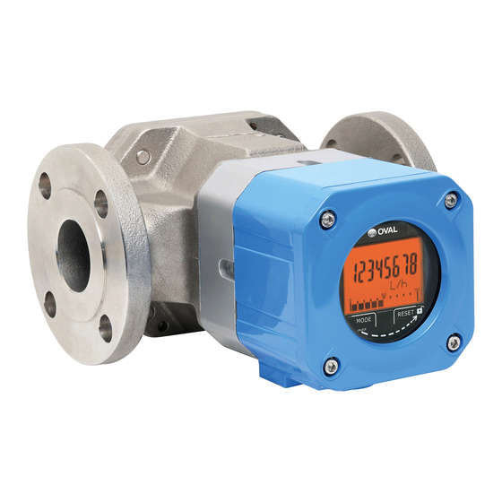
High Temp./Low Temp. Service and Jacketed
ULTRA OVAL
Every ULTRA OVAL is fabricated and shipped from our factory under stringent quality control. In order
to maintain its design performance throughout the life of the meter, this manual offers the operator the
necessary installation, operation and maintenance information.
Be well familiar with these instructions before you place the meter in service and keep this manual at the
field location for ready reference.
The standard, high temperaure-, low temperature-service, and jacketed type meters all have in common
the same specifications described in this instruction manual except for some difference in the jacketed
type on its piping procedure and operating precautions. Be careful to observe the instructions given with
a reminder "See also page 18 for the jacketed type."
◆ About Meter Size Designation ◆
The size of OVAL positive-displacement flowmeters is basically identified by a two-digit code. For
complate details, see Section 18 PRODUCT CODE CONFIGURATION..
Meter Sizes 50, 52, 53, 55, 56, 57
Register type A
Meter Size 57
with cooling tube
Ins. No. B-144-12-E
Meter Size 50
with cooling tube
Meter Sizes 52, 53, 55, 56
with heating tube
Advertisement
Table of Contents

Related Manuals for Oval ULTRA OVAL


Summary of Contents for Oval ULTRA OVAL
- Page 1 Every ULTRA OVAL is fabricated and shipped from our factory under stringent quality control. In order to maintain its design performance throughout the life of the meter, this manual offers the operator the necessary installation, operation and maintenance information.
-
Page 2: Table Of Contents
B-144-12-E CONTENTS ......................4 1. BEFORE YOU BEGIN 1.1 Confirming the Nameplate ....................... 4 1.2 Transportation Considerations ....................4 1.3 Storage Considerations ......................4 1.4 Considerations on Construction ....................5 ....................5 2. OPERATING CONDITIONS 2.1 Operating Conditions for Explosionproof Model ..............6 ...................... - Page 3 B-144-12-E 11.3 Accumulated Total and Instantaneous Flowrate Calculations ..........28 11.4 Parameter List ........................29 11.5 Parameter Setup Procedure ....................31 11.5.1 Procedure to Modify a Parameter ................31 11.5.2 Procedure to Enter a Parameter ................. 31 11.5.3 About Dummy Output Features (special functions) ............ 33 11.5.4 Parameter Initialization ....................
-
Page 4: Before You Begin
If your Ultra Oval is stored for long periods of time upon receipt before installation, unexpected faulty conditions could result. If a long-term storage is anticipated, take the following precautions: (1) Keep your Ultra Oval in store in the same shipping container used for transportation from Oval if possible. -
Page 5: Considerations On Construction
2. OPERATING CONDITIONS Made In Japan MNPJ-237 OVAL Corporation To maintain the stated high accuracy and long MODEL service life of OVAL flowmeter, make sure that TAG. No MAX PRESS. flowrate, pressure, temperature and viscosity are FLOW RANGE within the ratings as stamped on the meter register ~... -
Page 6: Operating Conditions For Explosionproof Model
B-144-12-E 3) This flowmeter is not provided with subtract function. If pulsation in the flow (where the fluid moves back and forth in the pipeline under the influence of pressure) or reversal of flow exists, the total counter may show erratic reading, accumulating all incoming pulses irrespective of flow direction. - Page 7 B-144-12-E Specification (2): Output not provided (Product code ends in 00.) Hazardous area Register (ex. type) Conn. terminals for external wiring Cable lead-in ※1 (w/close-up plug) Fig. 2. 2 NOTE: Detailed explanation of asterisks ※1 through ※4 in Figs. 2.1 and 2.2. Explosionproof enclosure of the ex type equipment is represented by a code Exd II BT4/Exia II BT4.
-
Page 8: General Description
B-144-12-E 3. GENERAL DESCRIPTION Ultra Oval has been developed to meet the needs of precise flowrate measurement. The local direct- reading total counter is an all-electronic register built around a single-chip CPU. With latest electronic technologies used throughout, this versatile register displays accumulated total flow, instantaneous flowrate (digital readout) and provides, by option, a pulse and analog output proportional to the rate of flow. -
Page 9: Lcd Counter Display
B-144-12-E 5. LCD COUNTER DISPLAY 5. 1 About "MODE" Switch Removing the selector magnet housed at the bottom of the register, hold it close to the field labelled "MODE" through the LCD counter glass faceplate and the display will scroll forward through available readings as shown below. -
Page 10: About The Displayed Messages During Operation
B-144-12-E 5.2 About the Displayed Messages during Operation (1) Ordinary operation (2) Prolonged operation "MODE" switch is turned "ON" Held turned ON without turning "OFF" (selector magnet held close to it.) immediately by removing the fingers. 8 bars appear. Bars begin to disappear from the left most one. Indicates a countdown before Indicates that the switch is turned "prolonged depression"... -
Page 11: Installations
(6) The strainer should be located upstream of, and as close to the meter as possible. (7) Since the sensor in Ultra Oval operates on the principle of sensing changes in magnetic flux density, it must be isolated from the influence of any external magnetic flux. In order to minimize the influence... -
Page 12: How To Change Flow Directions
B-144-12-E 7. HOW TO CHANGE FLOW DIRECTIONS CAUTION: Do not fail to turn power OFF if the meter is of remote output type. Change the orientation of the register and flowmeter body such that they agree with the actual flow direction desired. -
Page 13: Wiring Instructions
B-144-12-E 8. WIRING INSTRUCTIONS (Refer also to the wiring instructions of respective receiving instrument instruction manual.) 8. 1 Wiring Connections at Terminals (1) Cables for field wiring The following cables should be used unless otherwise specified: Cables l.25mm in conductor area and 8.5 - 12 mm in finished O.D. As to the number of conductors, select 2 to 4 according to your particular application. -
Page 14: Method Of Connections
+ ※ 4/20mA × load resistance. Totalizer − NOTE 2: If you use an OVAL receiving instrument in the configuration shown here, make sure of the current + Analog Indicator carrying capacity of receiving instrument's power −... -
Page 15: Operating Instructions
B-144-12-E 9. OPERATING INSTRUCTIONS 9.1 Operation (See page 18 for the jacketed type.) At first-time operation, carefully operate in the following sequence, allowing the flow within the flow range specified. (Refer to the piping diagram below.) Flow Direction Valve Strainer Meter Bypass Line (1) Shut off the valve (A) on the inlet side and the valve (B) on the outlet side and then open the bypass... -
Page 16: Operating Precautions
B-144-12-E 9.2 Operating Precautions (1) When changing flowrates In applications where the flowrate varies or Excessive flow Rapid Flow Variation where shutoff valve opening and closure takes place in batch operation, avoid rapid changes in flowrate across the meter. As a rule of thumb, one second per 25 millimeters (1") in connecting pipe diameter is acceptable as the permissible changes in flowrate. -
Page 17: Precautions At Operation Shutdown
B-144-12-E 9.3 Precautions at Operation Shutdown ( See also page 18 for the jacketed type.) (1) Valves should be closed progressively. Rapid valve closure could, under certain piping conditions, cause a sharp pressure rise by water hammer, or hydraulic shock, resulting in damage to the meter. (2) Precautions against pressure buildup on closure Complete closure of valves upstream and downstream of the meter makes the affected section a totally enclosed chamber and a pressure buildup relative to a rise in atmospheric temperature could... -
Page 18: Piping Instructions And Operating Precautions Of Jacketed Meters
B-144-12-E 9.6 Piping Instructions and Operating Precautions of Jacketed Meters ◆ Hot water or steam jacketed meters require piping work in the following manner: (1) Piping to the meter body remains the same as that of standard meters (meters not jacketed). (2) Adhere to the following instructions for the piping to the jacket: Steam Jacketed Hot-water Jacketed... -
Page 19: Disassembly And Inspecting
Ultra Oval. Exercise care to keep individual members disassembled free from grit and dust. -
Page 20: Size 50 Meter Body Assembly Procedure
10. 2 Size 50 Meter Body Assembly Procedure PRECAUTIONS BEFORE ASSEMBLY Oval rotors, inner walls of the rotor shafts, inner wall of the measuring chamber, inlet and outlet ports, and inner surface of the rear cover should be thoroughly washed clean, completely removing dust, grime and other foreign matter. - Page 21 B-144-12-E ③ Front Cover Installation Firstly install the O-ring (108) on the front cover. If the O-ring is damaged or swollen with metered liquid, it will not fit in the groove. If such is the case, replace with a new one. Align the locating pin of front cover with its pin slot in the meter body and, fitting the rotor shafts into rotor shaft sockets on the front cover, force the...
-
Page 22: Sizes 52, 53, 55, 56, 57 Meter Body Disassembly And Inspection
Rotor Shafts them for condition. (The rotor shafts should be drawn out straight.) (a) Make sure to see if the Oval rotors are jammed with foreign matter. Rear (b) Check to see if the rotors, shafts and other Cover members are worn. -
Page 23: Sizes 52, 53, 55, 56, 57 Meter Body Assembly Procedure
10.4 Sizes 52, 53, 55, 56, and 57 Meter Body Assembly Procedure PRECAUTIONS BEFORE ASSEMBLY Oval rotors, inner walls of the rotor shafts, inner wall of the measuring chamber, inlet and outlet ports, and inner surface of the rear cover should be thoroughly washed clean, completely removing dust, grime and other foreign matter. - Page 24 B-144-12-E Rear Cover End Plate Gasket ④ Installing end plate and confirming freely ⑤ Rear Cover Installation Firstly install the gasket (104) on the rear cover. rotor rotation With the locating pin of end plate in phase with If the gasket is found damaged, replace it with a its pin slot in the meter body and fitting the rotor new one.
-
Page 25: Register Switch Functions And Parameter Setup
B-144-12-E 11. REGISTER SWITCH FUNCTIONS AND PARAMETER SETUP 11.1 Switch Names Front Cover Hex Socket Head Bolts O-Ring ① Using hex key, remove four hex socket head bolts ② Removing the front cover provides access to the securing the front cover. electronics unit. -
Page 26: Function Setup Switch "Sw2
B-144-12-E 11.1.1 Function Setup Switch "SW2" DIP Switch No. Description of Functions Parameter write-protect SW2−1 OFF: Rewritable "Default" ON: Write protect * To seal, set to ON before pasting the seal. SW2−2 Factored/unfactored pulse select OFF: Factored pulse ON: Unfactored pulse SW2−3 Inhibit to reset the resettable total OFF: Resettable "Default"... -
Page 27: Individual Test Pin Functions
Timing remains the same as that of FWD and its 3V app. waveform is one before unfactored output amplification. Accepts a simulated pulse train OVAL pulse checker Model PC2201, or other signal source. Input mode is PG30 mode of Model PC2201. It also accepts pulses with levels "0": 1V max. -
Page 28: Accumulated Total And Instantaneous Flowrate Calculations
B-144-12-E 11.3 Accumulated Total and Instantaneous Flowrate Calculations (1) Total flow ........Both accumulated total and resettable total Q = P×F×H where P: Number of incoming pulses F: Meter factor H: Conversion factor (2) Instantaneous Flowrate ....Valid only for input pulses of small periodic variation The period of incoming pulses for the sample cycle number is measured in units of 30μsec and substituted in the following formulas for readout: 3600×F×H×A... -
Page 29: Parameter List
B-144-12-E 11.4 Parameter List Parameter Code Default Setting Description Remarks Depends on the Meter factor Ex.: Given meter factor 9.918mL/P. ● customer (Unit: [□/Pulse]) To change the indicated flowrate to [L] Meter factor specification. Setting range: →9.918 [mL/P]=9.918×10 [L/P] −3 ●... - Page 30 B-144-12-E Parameter Code Default Setting Description Remarks 1 or 50 Factored pulse output Ex.: To change pulse width from 1ms "An item shown on "ON" width to 50ms Pulse width parameter label" (Unit: [msec]) → Set to "Pon 50" (msec). (Note 4) Not a parameter Furnishes a 1Hz...
-
Page 31: Parameter Setup Procedure
B-144-12-E 11.5 Parameter Setup Procedure 11.5.1 Procedure to modify a parameter Given below is the parameter setup procedure: ① In "Measure Mode (normal mode)," turn MODE switch ON for 5 seconds to go into "Review Mode." ② Using MODE and RESET switches, show the parameter you want to modify. ③... - Page 32 B-144-12-E Kind 2 Decimal point setup parameters (bP, SP) In the parameter setup mode, a figure representing the decimal places of interest flickers. MODE ..Not used in the setup process. RESET ..Each time the switch is turned ON, the decimal point moves one place to the left and the figure increases by one.
-
Page 33: About Dummy Output Features (Special Functions)
B-144-12-E 11.5.3 About Dummy Output Features (special functions) By the following steps, a 1Hz or 10Hz simulated factored pulse train can be furnished irrespective of flowmeter measurement. NOTE: This feature is not available with the unfactored pulse output specification. 1Hz simulated output mode (dummy output 1 mode Code: Pd1) ●... -
Page 34: About Error Messages
B-144-12-E 11.5.5 About Error Messages The electronics unit can be reconfigured for new parameters at your option. However, if some parameters you set up conflict, or when an erratic condition arises, the LCD display will tell you with an error message from Table 11.1 below. - Page 35 B-144-12-E Table 11.2 Menu Trees and Switch Operation Measure mode (normal mode) Parameter review mode...
-
Page 36: Sensor Replacement Procedure
B-144-12-E 12. SENSOR REPLACEMENT PROCEDURE NOTE: Size 55 meter body is shown here. The same procedure applies to other size models. Adapter Hex Socket Register Assembly Register Assembly Head Bolts ② Carefully draw the register assembly out. Exercising ① Take off four hex socket head screws on the register. care not to bump the sensor against adjacent com- ponents, draw it out in the horizontal direction. -
Page 37: Battery Replacement Procedure
IMPORTANT Battery pack without external output Battery pack with external output (4 batteries) (1 battery) When you replace batteries, contact your nearest OVAL designated service station and use dedicated battery Appearance packs. WARNING Life (with battery This dedicated battery pack is of Approx. -
Page 38: Troubleshooting
4. Battery has run down. 4. Referring to the instructions on page 37, replace the battery pack. 5. Oval rotors jammed with foreign matter; 5. Referring to Disassembly and Inspection rotors locked; metered liquid fails to run. Procedure (page 19), disassemble meter body and clean the rotors thoroughly. -
Page 39: Exploded Views And Parts List
B-144-12-E 15. EXPLODED VIEWS AND PARTS LIST 15.1 Size 50 Exploded View and Parts List When you order replacement parts, specify the stock No., flowmeter model, instruction manual ● No., symbol No., part name and the quantity desired. ◇ ◇ Exploded View 123A 123B... -
Page 40: Sizes 52 And 53
B-144-12-E 15.2 Sizes 52 and 53 Exploded View and Parts List ● When you order replacement parts, specify the stock No., flowmeter model, instruction manual No., symbol No., part name and the quantity desired. ◇ ◇ Exploded View 700A 700B 155 151 ◆... -
Page 41: Sizes 55 And 56
B-144-12-E 15.3 Sizes 55 and 56 Exploded View and Parts List ● When you order replacement parts, specify the stock No., flowmeter model, instruction manual No., symbol No., part name and the quantity desired. ◇ ◇ Exploded View 700A 700B 155 151 153 156 158 152... -
Page 42: Size 57
B-144-12-E 15.4 Size 57 Exploded View and Parts List When you order replacement parts, specify the stock No., flowmeter model, instruction manual ● No., symbol No., part name and the quantity desired. ◇ ◇ Exploded View 700A 700B 108 103 114 153 154 ◆... -
Page 43: General Specifications
B-144-12-E 16. GENERAL SPECIFICATIONS 16.1 Basic Meter Meter Size 56, 57 Item Nominal Diameter 20mm 25 mm 40mm 50mm JIS 10K RF, ASME 150 RF, JPI 150 RF Flange Ratings JIS 16, 20, 30K RF, ASME 300 RF, JPI 300 RF, DIN 10, 16, 20, 25 Operating Temperature Range −... -
Page 44: Register General Specifications
B-144-12-E 16.2 Register General Specifications Size , 52, 53 55, 56 ※ ※ Item Total count (8-digit) Local 0.01L(standard) 0.1L(standard) 1L(standard) Display Resettable 0.1L, 1L 1L, 0.01㎥ 0.01㎥, 0.1㎥ C mode (LCD) total(7-digit) Mode b1 mode 1 L/h (standard) 1 L/h (standard) Instantaneous Select flowrate (4-digit) b2 mode... -
Page 45: Outline Dimensions
B-144-12-E 17. OUTLINE DIMENSIONS All dimensions in millimeters Cooling tube Heating tube RESET RESET MODE MODE MODE ×10 ml b1 : × 1 1/h b2 : × 10 s1/sis Cable Entry G1/2 (Remode output Provided model only) ①... -
Page 46: Product Code Configuration
① ② ③ Model ⑯ Regulations L U S ULTRA OVAL (integral type) all stainless Standard L U J ULTRA OVAL (integral std. jacket) Element: stainless steel G High Pressure Gas Safety Act (Approved product) ※ w/Material test certificate ※ w/Material test certificate ④... - Page 47 B-144-12-E Ex-proof temp. class Regulations Explosion-proof Register Power supply Process connection Major material Output Version Temp. category Fluid category Bearing Nominal diameter Viscosity category Capacity (Nominal Diameter) Seal material Model Special ① ② ③ ④ ⑤ ⑥ − ⑧ ⑨ ⑩...
-
Page 48: Notes On Explosion-Proof Type For China (Nepsi)
The new product code has been implemented since April 2017. Therefore, the configuration of old product code will not be updated after April 2017. Contact OVAL if you wish to order with the old product code for reasons such as type approval. Product Code... - Page 49 B-144-12-E...
- Page 50 B-144-12-E...
- Page 51 B-144-12-E...
- Page 52 B-144-12-E 2020.02 Revised 2019.02 Revised△ All specifications are subject to change without notice for improvement. B-144-12-E (1)...
Need help?
Do you have a question about the ULTRA OVAL and is the answer not in the manual?
Questions and answers