Table of Contents
Advertisement
Quick Links
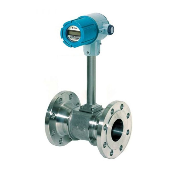
Battery Powered Vortex Flowmeters
EX DELTA, EX DELTA・DIA
Fixed/replaceable sensor and integrally/separately-mounted
preamplifier types
Wafer type
(Fixed sensor)
Flanged separately
mounted sensor
(Replaceable sensor)
Every OVAL product is fabricated and shipped from our factory under stringent quality control. In order to
maintain its design performance throughout its life, this manual offers the operator the necessary installation,
operation and maintenance information. Be well familiar with these instructions before you place the meter in
service and keep this manual for ready reference.
Meter Model
: VX
Flanged type
(Fixed sensor)
Wafer type separately
mounted sensor
(Fixed sensor)
I ns. No. D-546-9-E
W
N
1
F
C
2 □□□-
□
R
Z
Wafer type
(Fixed sensor)
Separately mounted
transmitter
G
1
L
10
-
23 10
2
S
H
Advertisement
Table of Contents

Related Manuals for Oval EX DELTA, EX DELTA-DIA


Summary of Contents for Oval EX DELTA, EX DELTA-DIA
- Page 1 (Fixed sensor) (Replaceable sensor) Every OVAL product is fabricated and shipped from our factory under stringent quality control. In order to maintain its design performance throughout its life, this manual offers the operator the necessary installation, operation and maintenance information. Be well familiar with these instructions before you place the meter in...
-
Page 2: Table Of Contents
D-546-9-E C O N T E N T S 1. HANDLING CONSIDERATIONS ・・・・・・・・・・・・・・・・・・・・・・・・・・・・・・・・・・・・・・・・・・・・・・・・・・・・・・・・・・・・ 5 1.1 Confirming the Specifications ・・・・・・・・・・・・・・・・・・・・・・・・・・・・・・・・・・・・・・・・・・・・・・・・・・・・・・・・・・・・・・・ 5 1.2 Transit Considerations ・・・・・・・・・・・・・・・・・・・・・・・・・・・・・・・・・・・・・・・・・・・・・・・・・・・・・・・・・・・・・・・・・・・・・・ 5 1.3 Storage Considerations ・・・・・・・・・・・・・・・・・・・・・・・・・・・・・・・・・・・・・・・・・・・・・・・・・・・・・・・・・・・・・・・・・・・・・ 5 2. OPERATING CONDITIONS ・・・・・・・・・・・・・・・・・・・・・・・・・・・・・・・・・・・・・・・・・・・・・・・・・・・・・・・・・・・・・・・・・ 5 3. GENERAL ・・・・・・・・・・・・・・・・・・・・・・・・・・・・・・・・・・・・・・・・・・・・・・・・・・・・・・・・・・・・・・・・・・・・・・・・・・・・・・・・・・ 6 4. COMPONENT NAMES AND FUNCTIONS ・・・・・・・・・・・・・・・・・・・・・・・・・・・・・・・・・・・・・・・・・・・・・・・・・・... - Page 3 D-546-9-E 10. CPU PARAMETER SETUP ・・・・・・・・・・・・・・・・・・・・・・・・・・・・・・・・・・・・・・・・・・・・・・・・・・・・・・・・・・・・・・・・・ 26 10.1 Procedure to Modify a Parameter ・・・・・・・・・・・・・・・・・・・・・・・・・・・・・・・・・・・・・・・・・・・・・・・・・・・・・・・・・・・ 26 10.2 Procedure to Enter a Parameter ・・・・・・・・・・・・・・・・・・・・・・・・・・・・・・・・・・・・・・・・・・・・・・・・・・・・・・・・・・・・ 26 10.3 List of Modifiable Parameters ・・・・・・・・・・・・・・・・・・・・・・・・・・・・・・・・・・・・・・・・・・・・・・・・・・・・・・・・・・・・・・ 28 ・Table 10.2 Menu Trees and Switch Operation ・・・・・・・・・・・・・・・・・・・・・・・・・・・・・・・・・・・・・・・・・・・・・・・・・・・ 29 11. MAINTENANCE ・・・・・・・・・・・・・・・・・・・・・・・・・・・・・・・・・・・・・・・・・・・・・・・・・・・・・・・・・・・・・・・・・・・・・・・・・・ 30 11.1 Sensor Replacement ・・・・・・・・・・・・・・・・・・・・・・・・・・・・・・・・・・・・・・・・・・・・・・・・・・・・・・・・・・・・・・・・・・・・・・...
- Page 4 D-546-9-E C O N V E N T I O N S Shown in this manual are the signal words NOTE, CAUTION and WARNING, as described in the examples below: ➡ ➡ NOTE: Notes are separated from the general text to bring the user’s attention to important information.
-
Page 5: Handling Considerations
D-546-9-E 1. HANDLING CONSIDERATIONS 1.1 Confirming the Specifications (1) When received, the meter should be thoroughly inspected for indication of rough handling during transit. (2) Product code number and ratings are stated on the meter nameplate. Make sure that the ratings shown conform to your particular specifications. 1.2 Transit Considerations (1) It is desirable that the meter be transported to the installation site in the shipping container used for transit from the factory. -
Page 6: General
OVAL’s many years of experience in the field shows up in the EX Delta Dia, another vortex meter, specifically designed for liquids with a high resistance to contamination. This meter is best suited for processes where ferrous meter components tend to become rusty, or where entrained foreign matter tends to build up. - Page 7 D-546-9-E EX Delta Dia Construction Fixed Sensor Type Replaceable Sensor Type Sensor Sensor Diamond-shaped Bluff Body Diamond-shaped Bluff Body Sensor Flow Diamond-shaped Bluff Body How vortices are formed and shed Fig. 3.1...
-
Page 8: Component Names And Functions
D-546-9-E 4. COMPONENT NAMES AND FUNCTIONS 4.1 Component Names (vortex pickup) (vortex pickup) ① Meter Body Consists of a measuring pipe and a vortex shedding body (bluff body). As the metered material flows, von Karman vortices form and shed behind the bluff body. ② Sensor (vortex pickup) ・... - Page 9 D-546-9-E ③ Adaptor Connects the meter body with the preamplifier. Also serves to protect the sensor and dissipate heat. ④ Preamplifier Transforms changes in electric charges generated from the sensor into an output signal representing the flowrate. Consists of the interface board, amplifier board, and display board. Preamplifier physical orientation is adjustable in steps of 90 deg.
-
Page 10: Totalizer Display Functions And Operation
D-546-9-E 4.2 Totalizer Display Function and Operation In normal operation, the display shows four different modes of reading, namely the accumulated total flow, hourly instantaneous flowrate, per-minute instantaneous flowrate, and resettable total flow, plus a low- battery indicator. 4.2.1 Operation with Mode Select Switch External to Preamplifier (1) Display Menu Selection The display scrolls through available readings each time the mode switch is pressed as shown in Fig. -
Page 11: Indicated Units Of Registration
D-546-9-E 4.2.4 About the Displayed Messages during Operation (1) Ordinary operation (2) Prolonged operation “MODE” switch is turned “ON” Held turned ON without turning “OFF” (selector magnet held close to it.) immediately by removing the fingers. ⇒ 8 bars appear. ⇒ Bars begin to disappear from the leftmost one. Indicates a countdown before Indicates that the switch is turned “prolonged depression”processing... -
Page 12: Piping Instructions
Accordingly, proper flow straightening measures must be taken when the application engineer considers installation of a DELTA meter. In applications where OVAL straightening devices (flow straightener, honey vane, and downstream pipe) are used, a straight pipe section is not required unless otherwise specified. -
Page 13: Pipes To Be Used
If required straight pipe space is not obtainable upstream of the vortex flowmeter due to existing restrictions on installation location, the OVAL Honey Vane S combined with a short pipe may be used to get around the space problem. EX Delta SS with a built-in Honey Vane S requiring no upstream straight pipe is accurate to ±... -
Page 14: Ripples
D-546-9-E 5.4 Ripples Compressors, Roots blowers and other ripple pressure generating sources could adversely affect meter performance. Minimize pulsating pressures by referring to the following formula: N < 22ρ V (Pa) where N: Pulsation pressure (Pa) ρ: Density (kg/m V : Minimum velocity (m/s) If pulsation pressure is excessive, the following measures should be taken into consideration: ①... -
Page 15: Prevention Of Slug Flow
D-546-9-E 5.7 Prevention of Slug Flow This meter can measure both gases and liquids, but slug flows (where gases exist in the process liquid) will produce a loss of metering accuracy. 5.8 Partially Filled Pipe When making a liquid measurement, ensure that the piping remains full of the process liquid. Installation in locations where it is difficult to keep the piping filled with the process liquid, or where bubbles tend to collect should be avoided. -
Page 16: How To Change Preamplifier Orientation
D-546-9-E 6.3 H o w t o C h a n g e P r e a m p l i f i e r Orientation The preamplifier can be oriented to the desired direction in 90° steps as shown in Fig. 6.3. ➡... -
Page 17: Separate-Mount Preamplifier Installation
D-546-9-E 6.4 Separate-Mount Preamplifier Installation ① The maximum transmission length from the probe is 200 meters; install the preamplifier within this length. ② The preamplifier requires installation on a horizontal or vertical steel pipe 2 inches in diameter with furnished U-bolt. ③ Select an installation location easy for maintenance and in a desirable environment. IMPORTANT Locations that comes under any of the following conditions should be avoided: ①... -
Page 18: How To Change Preamplifier (Totalizer) Display Angle
D-546-9-E 6.5 How to Change Preamplifier (Totalizer) Display Orientation The display (totalizer) can be rotated to the desired direction in 90° steps through 360° . By changing the angle of display board (internal assembly), the totalizer display appears for maximum readability on a vertical run or a horizontal run. Horizontal Run Vertical Run 〈How to Change Display Angle〉... -
Page 19: Installation Procedure
D-546-9-E 6.6 Installation Procedure Install the meter body in the following manner: 6.6.1 Wafer Type ① Install adjust rings on the meter periphery at both ends. ASME 150 and JPI 150 meters 25 millimeters in nominal diameter do not require adjust rings. Nominal Dia. 10mm to 25mm Nominal Dia. 40mm to 150mm ② Fitting flange gaskets at both sides, sandwich the meter body between flanges. CAUTION: E xercise care not to allow flange gaskets to extrude into the interior of the meter (pipe), or meter accuracy will suffer. -
Page 20: Flanged Type
D-546-9-E 6.6.2 Flanged Type ① Align the meter flange periphery with the pipeline flange periphery and bolt them together with hex bolts. ② It is preferable to use the flange gaskets furnished with the meter. CAUTION: Do not use flange gaskets the I.D. of which is smaller than the meter I.D. Do not allow flange gaskets to protrude into the meter body (pipe), or meter accuracy... -
Page 21: Wiring Connections, Separate Type
D-546-9-E 7. WIRING CONNECTIONS, Separate Type 7.1 Wiring Specifications Table 7.1 Cable Entry G 1/2 (PF 1/2) internal threads Transmission Length Probe to preamplifier: 200 meters max. Probe to preamplifier: 3-conductor shielded cable 1.25mm min. Cable Used Finished outside diameter: φ13.5mm max. Terminal Block Cross recess pan head screws, M3.5 7.2 Considerations on Wiring Connections (1) To eliminate the possibility of stray current... -
Page 22: Separate-Mount Preamp To Probe Terminal Box Wiring Diagram
D-546-9-E 7.3 Separate-mount Preamp to Probe Terminal Box Wiring Diagram... -
Page 23: Operation
D-546-9-E 8. OPERATION 8.1 Flushing the Piping Assembly On a newly installed piping assembly where scale, sludge and other foreign matter are expected, flushing the piping assembly is necessary before commencing meter operation. In order to safeguard the meter, use a bypass line for flushing. -
Page 24: Flow Sensitivity Adjustment Procedure
D-546-9-E 9. FLOW SENSITIVITY ADJUSTMENT PROCEDURE Flow sensitivity is accurately adjusted over the specified flow range before the meter leaves the factory. If no output appears at the minimum flowrate p r e s u m a b l y d u e t o y o u r s p e c i f i c o p e r a t i n g conditions (disturbance from external interference, for example), readjust the sensitivity (trigger level). - Page 25 D-546-9-E You can effectively get around the problem of erratic pulse generation attributable to noises of pipeline oscillation, pulsating flows, etc. with no flow by selecting a higher TLV pot position. The trigger level is factory adjusted to 160mV p-p before shipment. ①...
-
Page 26: Cpu Parameter Setup
D-546-9-E 10. Parameter Setup Procedure 10.1 Procedure to modify a parameter Given below are the steps to change current parameters to new ones: (This parameter modification procedure uses MODE and RESET switches in the internal electronics. See Fig. 11.11 on page 33.) ① In “Measure Mode (normal mode) , ”hold MODE switch depressed for 5 seconds to go into “Review Mode.” ②... - Page 27 D-546-9-E [Kind 2] Unit setup parameter “Un” In the parameter setup mode, the unit to be set up flickers. MODE・・・ Not used in the setup process. RESET・・・ With each ON, the screen scrolls through available units. → On locating the desired unit, press MODE for 2 sec. ( The new setting is established and the screen returns to the review mode.) Example: Parameter“Un”(Units indicated) Indicated unit(flickers)
-
Page 28: List Of Modifiable Parameters
D-546-9-E 10.3 List of Modifiable Parameters Table 10.1 Parameter Code Default Setting Initial Value Description Example of Setup or Remarks ・Meter factor Ex.: Given meter factor 9.918L/P. (Unit: [ □ /Pulse]) To change the indicated flowrate to ・Setting range: read in [m 0.9999-9 to 9.9999E7 →... - Page 29 D-546-9-E Table 10.2 Menu Trees and Switch Operation None Accumulated total flow Instant. flowrate (hourly) Inst.flowrate (per-min.) NOTE: Goes back to the screen before a switch to the review mode. Resettable total flow NOTE: Retains variables before a switch Measure mode (normal mode) to the review mode.
-
Page 30: Maintenance
D-546-9-E 11. MAINTENANCE CAUTION: The sensor is a pressuretight member. Be sure therefore to stop the flow and reduce the line pressure to zero when you remove it. A leak check is suggested after sensor replacement for added safety. 11.1 Sensor Replacement 11.1.1 Fixed Sensor Removal PROCEDURE See Sec. 14.1 Fixed Sensor Exploded View and Parts List on pages 39 and 40. ① Turn off “POWER” switch on the display board (see Fig. 6.11 on page 18). ②... -
Page 31: Replaceable Sensor Removal
D-546-9-E 11.1.3 Replaceable Sensor Removal CAUTION: Since the sensor does not come in contact with the fluid (located external to the housing), it can be replaced without need of interrupting the fluid flow. But for safety, replace the sensor at temperatures below 220℃. 〈PROCEDURE〉 See Sec. 14.2 Replaceable Sensor Exploded View and Parts List on pages 41 and 42. ① Turn off “POWER” switch on the display board (see Fig. -
Page 32: Replaceable Sensor Installation
D-546-9-E 11.1.4 Replaceable Sensor Installation 〈PROCEDURE〉 The assembly is reverse of the removal procedure, observing the following ① Exercise care not to drop or force the sensor, or it may be damaged. ② When you install the sensor, make sure that sensor's locating pin fits in the mating pin slot in the oscillating spool, and carefully insert the sensor into place. -
Page 33: Preamplifier Inspection
D-546-9-E 11.2 Preamplifier Inspection Input Board 11.2.1 Description of Test Pins (1) Amplifier Board A NAME TEST PINS DESCRIPTION While measurement is being made +・・・ VTX Amplified vortex waveform 0V -・・・ 0.1V p-p min. +・・・ TRG Pulse sync with vortex 3.0V p-p approx. (Before low cutoff filter) 0V... -
Page 34: Switch And Potentiometer Settings
D-546-9-E 11.2.2 Switch and Potentiometer Settings (1) Amplifier Board A NAME SYMBOL DESCRIPTION Amplification factor of the amplifier is factory adjusted relative to Amplification adjust the sensor used. Readjustment is basically not required except potentiometer when the sensor is replaced with a new one. (See Sec.9 FLOW SENSITIVITY ADJUSTMENT PROCEDURE.) Sets the trigger level (pulse generation threshold sensitivity) to Trigger level adjust somewhere between 80mV and 350mV p-p. - Page 35 D-546-9-E (3) Display Board NAME SYMBOL DESCRIPTION Parameters write ptotected Write protect switch Parameters write enabled In the accumulated total mode, turning “ON” → “OFF” resets the Accumulated total total reading. reset switch Normally set to “OFF.” (No function) Always set to OFF . Turns power (battery) ON.
-
Page 36: Preamplifier Block Diagram
D-546-9-E 11.3 Preamplifier Block Diagrams... -
Page 37: Battery Replacement
D-546-9-E 12. BATTERY REPLACEMENT When the “ ” indicator begins to blink in the display, replace the internal battery pack according to the following procedure: ④ Unplug the battery pack connectort ① . ① Remove the windowed cover of the preamplifier. ②... -
Page 38: About Error Messages
D-546-9-E 13. ABOUT ERROR MESSAGES Parameters may be changed as you choose in this flow computer, but if inconsistent, conflicting parameters are entered, or when faulty conditions take place, the preamplifier LCD display will tell the operator with error messages as shown in Table 13.1 below. Message Name Description... -
Page 39: Exploded View And Parts List
D-546-9-E 14. EXPLODEDED VIEW AND PARTS LIST 14.1 Fixed Sensor NOTE: Parts list on the next page. ➡ ➡... - Page 40 D-546-9-E ● Parts List Sym. No. Part Name O'ty Remarks Sym. No. Part Name O'ty Remarks Meter Body 300A Preamplifier w/totalizer 1 set PA35 Separately-mounted φ17.5× t2 Gasket A 300C 1 set PA35 Preamp. with totalizer Sensor 300D Terminal Box 1 set Hex Socket Head Bolt A M5×13 Display Board...
-
Page 41: Replaceable Sensor Type
D-546-9-E 14.2 Replaceable Sensor Type NOTE: See next page for parts list. ➡ ➡... - Page 42 D-546-9-E ● Parts List Sym. No. Part Name Q'ty Remarks Sym. No. Part Name Q'ty Remarks Meter Body 300A Preamplifier with Totalizer 1 set PA35 Sensor Unit 1 set Separately-mounted 300C 1 set PA35 Preamp with Totalizer 1001 Oscillating Spool 300D Terminal Box 1 set 1002 Sensor...
-
Page 43: General Specifications
D-546-9-E 15. GENERAL SPECIFICATIONS 15.1 Sensor Specifications 15.1.1 EX Delta Sensor Specifications Tabele 15.1 Item Description Sensor type Fixed sensor Fixed sensor Replaceable sensor Nominal size (mm) 10, 15, 25, 40, 50, 80, 100, 150 40, 50, 80, 100, 150, 200, 250, 300 40, 50, 80, 100, 150, 200, 250, 300 Body style Wafer type Flanged type (RF is standard.) Flanged type (RF is standard.) -
Page 44: Ex Delta Dia Probe Specifications
D-546-9-E 15.1.2 EX Delta Dia Sensor Specifications Table 15.2 Item Description Sensor type Fixed sensor Fixed sensor Replaceable sensor Nominal size 15, 25, 40, 50, 80mm 50, 80mm 50, 80mm Body style Wafer type Flanged type (RF is standard.) Flanged type (RF is standard.) Flange rating JIS 10, 16, 20, 30K ASME/JPI 150, 300 Std. -
Page 45: Indicated Units Of Measure
D-546-9-E 15.2 Indicated Units of Measure 15.2.1 EX Delta, Indicated Units of Measure Shown in this table are the units of measurement indicated at volume flowrates. Table 15.3 Appli- Nominal meter factor, Indicated units Nominal Dia. Max. flowrate, m cable of measure (m mm (inch) (Unfactored pulse freq., Hz) fluid (Nom. -
Page 46: Preamplifier Specifications
D-546-9-E 15.3 Preamplifier Specifications Table 15.5 ITEM DESCRIPTION Model PA35 On of the following two is selected: Mounting Design Integrally mounted with flowmeter, or separately mounted (installed on a 2” pipe) ※1 Waterproof JIS C 0920, jetproof (IEC IP65) (IP65) Explosionproof Intrinsic safety explosionproof:Exia Ⅱ... -
Page 47: Pressure Losses
D-546-9-E 15.4 PRESSURE LOSSES 15.4.1 EX Delta Pressure Losses C ×ρ ● Nom. Diameters 10 to 150mm Δ Ρ= where Δ Ρ : Pressure loss (kPa) ※ 10mm IS FOR LIQUIDS ONLY ρ : Density (kg/m To determine the pressure loss, find the value C at the inter- secting point of flowrate (Q) and slanted line of the given meter diameter and substitute... -
Page 48: Ex Delta Dia Pressure Losses
D-546-9-E 15.4.2 EX Delta Dia Pressure Losses ● Nom. Diameters 15 to 80mm C ×ρ Δ Ρ= where Δ Ρ : Pressure loss (kPa) ρ : Density (kg/m To determine the pressure loss, find the value C at the inter- secting point of flowrate (Q) and slanted line of the given meter diameter and substitute it to the formula adove. -
Page 49: Outline Dimensions
D-546-9-E 16. OUTLINE DIMENSIONS 16.1 EX Delta, Wafer Type Nominal dia. 10, 15, and 25mm Separately-mounted Preamp Type Nominal dia. 40 to 150mm Separately-mounted Preamp Type Approx. Weight (kg) φ d Nom.dia. φ D Provided with (mm) (Meter I.D.) Integral with preamp separate preamp 10 (3/8”) 32.5 15 (1/2”) -
Page 50: Ex Delta, Flanged Type
D-546-9-E 16.2 EX Delta, Flanged Type Nominal Dia. 40 to 150mm All dimensions in millimeters Separately-mounted Preamp Type Nominal Dia. 200 to 300mm Separately-mounted Preamp Type Approx. Weight (kg) φ d Nominal Dia. Provided with (mm) (Meter inside dia.) Integral with preamp separate preamp 40 (1-1/2”) 85.5 37.6... -
Page 51: Ex Delta Dia, Wafer Type
D-546-9-E 16.3 EX Delta Dia, Wafer Type Nominal Dia. 15, 25mm Separately-mounted Preamp Type Nominal Dia. 25mm Nominal Dia. 40 to 80mm Separately-mounted Preamp Type φ d Approx. Weight (kg) Nominal Dia. φ D (Meter inside Provided with (mm) Integral with preamp diameter) separate preamp 15 (1/2”) 32.5 14.5... -
Page 52: Ex Delta Dia, Flanged Type
D-546-9-E 16.4 EX Delta Dia, Flanged Type Nom. dia. 50 and 80mm Approx. Weight (kg) φ d Nominal dia. (mm) (Meter I.D.) Provided with Integral with preamp separate preamp 50 (2”) 52.7 80 (3”) 78.1 15.0 15.2 ➡ ➡ NOTE:JIS 10K dimensions and weight are shown here. ➡... -
Page 53: Replaceable Sensor Type
D-546-9-E 16.5 Replaceable Sensor Type 16.5.1 EX Delta, Flanged Type Nominal Dia. 40 to 150mm Separately-mounted Preamp Type Nominal Dia. 200 to 300mm Separately-mounted Preamp Type Approx. Weight (kg) φ d Nominal Dia. (mm) Provided with (Meter inside dia.) Integral with preamp separate preamp 40 (1-1/2”) 85.5 37.6 50 (2”) -
Page 54: Ex Delta Dia/Flanged Type Pressure Losses
D-546-9-E 16.5.2 EX Delta Dia, Flanged Type Nom. dia. 50 and 80mm Approx. Weight (kg) φ d Nominal dia. (mm) (Meter I.D.) Provided with Integral with preamp separate preamp 50 (2”) 52.7 80 (3”) 78.1 15.6 15.8 ➡ ➡ NOTE:JIS 10K dimensions and weight are shown here. ➡... -
Page 55: Flow Straightener And Downstream Short Pipe
D-546-9-E 16.7 Flow Straightener and Downstrearm Short Pipe Flow Straightener Outline Dimensions Flow Straightener Outline Dimensions Dimensions (mm) Approx.Weight (kg) Nom. Dia. Model JIS 20K JIS 30K mm (in.) d φ JIS 10K ASME 150 ASME 300 20 (3/4) 21.4 25 (1) 27.2 32 (1・1/4) 35.5 40 (1・1/2) 41.2... -
Page 56: Product Code Explanation
D-546-9-E 17. PRODUCT CODE EXPLANATION 17.1 Battery Powered EX Delta Table 17.1 Product Code Item Description ① ② ③ ④ ⑤ ⑥ ⑦ - ⑧ ⑨ ⑩ ⑪ - ⑫ ⑬ ⑭ ⑮ Model EX DELTA Wafer type (Nom. sizes: 10 to 150mm) Fixed sensor type Body Style Flanged type (Nom. -
Page 57: Battery Powered Ex Delta Dia
D-546-9-E 17.2 Battery Powered EX Delta Dia Table 17.2 Product Code Item Description ① ② ③ ④ ⑤ ⑥ ⑦ - ⑧ ⑨ ⑩ ⑪ - ⑫ ⑬ ⑭ ⑮ Model V X EX DELTA Wafer type (Nominal sizes: 15 to 80mm) Fixed sensor type See Note 3. - Page 58 D-546-9-E 2011.11 Revised △ All specifications are subject to change without notice for improvement. D-546-9-E (1)
Need help?
Do you have a question about the EX DELTA, EX DELTA-DIA and is the answer not in the manual?
Questions and answers