Table of Contents
Advertisement
Quick Links
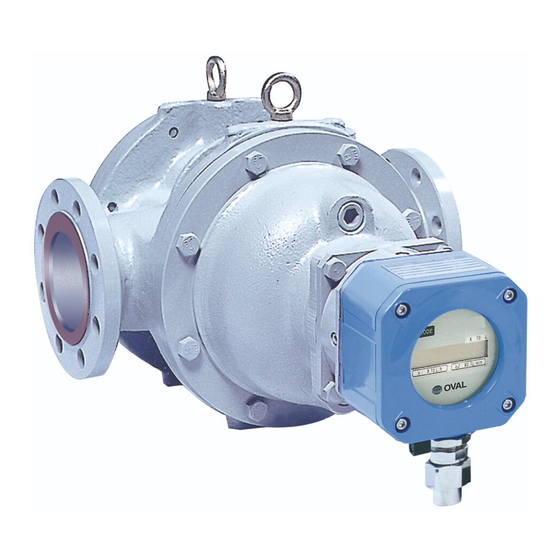
ULTRA UF-II
Meter Sizes 82, 83, 84, 85, 86, 87 & 88
Register Models A (Standard type)
<Meter sizes 85, 86, 87, and 88>
Every ULTRA UF- II (electronic register equipped flowmeter) is fabricated and shipped from our factory under
stringent quality control. In order to maintain its design performance throughout its life, this manual offers the
operator the necessary installation, operation and maintenance information.
Be well familiar with these instructions before you place the meter in service and retain this manual at the field
location for ready reference.
◆ About Meter Size Designation◆
The size of OVAL positive-displacement flowmeters is basically identified by a two-digit
code. For details, see Section 19 Product Code Explanation.
B-526-10N-E
Ins. No.
H (Smart type)
<Meter sizes 82, 83, and 84>
1
Advertisement
Table of Contents

Related Manuals for Oval ULTRA UF-II


Summary of Contents for Oval ULTRA UF-II
- Page 1 Be well familiar with these instructions before you place the meter in service and retain this manual at the field location for ready reference. ◆ About Meter Size Designation◆ The size of OVAL positive-displacement flowmeters is basically identified by a two-digit code. For details, see Section 19 Product Code Explanation.
-
Page 2: Table Of Contents
B-526-10N-E CONTENTS ● CAUTION: marked sections apply to Smart type. Page 1. BEFORE YOU BEGIN ........................5 1.1 Confirming the Nameplate ......................... 5 1.2 Transportation Considerations ........................5 1.3 Storage Considerations..........................5 1.4 Structural Considerations........................... 6 2. OPERATING CONDITIONS ......................6 2.1 Operating Conditions for Explosionproof Model .................. - Page 3 B-526-10N-E 9. OPERATING INSTRUCTIONS .......................24 9.1 Operations Sequence..........................24 9.2 Precautions for Models without Battery Pack ..................25 9.3 About the Register Life ..........................25 10. DISASSEMBLY AND INSPECTION [SUBJECT INDEX (1)] ............26 10.1 Meter Sizes 82 through 84 ........................27 10.1.1 Disassembly ...........................
- Page 4 B-526-10N-E 16. EXPLODED VIEWS AND PARTS LIST [SUBJECT INDEX (2)] ...........51 16.1 Sizes 82 and 83 Exploded View and Parts List ..................52 16.1.1 Sizes 82 and 83 Exploded View ..................... 52 16.1.2 Sizes 82 and 83 Parts List ......................53 16.2 Sizes 84 Exploded View and Parts List ....................
-
Page 5: Before You Begin
If an OVAL flowmeter is stored for long periods of time upon receipt before installation, unexpected faulty conditions could result. If a long-term storage is anticipated, take the following precautions: (1) Keep your OVAL flowmeter in store in the same shipping container used for transportation from OVAL if possible. -
Page 6: Structural Considerations
CONT . To maintain the stated high accuracy and long TEMP. FULL SCALE PULSE UNIT service life of OVAL UF-II flowmeter, make sure that SERIAL No. DATE SIZE flowrate, pressure, temperature and viscosity are held within the ratings shown in the nameplate... -
Page 7: Operating Conditions For Explosionproof Model
B-526-10N-E 2.1 Operating Conditions for Explosionproof Model This product is approved as explosionproof. Failure to comply with the following conditions will automatically nullify this rating. (1) Do not perform any unauthorized modification to this product. (2) Before opening the enclosure, if necessary for some reason, ensure safety against hazards associated with flammable gases present in the atmosphere. - Page 8 B-526-10N-E Specification (2): Output not provided (Product code ends in 00.) Harardous area Conn. terminals Register (ex. type) for external wiring Cable lead-in * 1 (w/close-up plug) Fig. 2.2 NOTE: Detailed explanation of asterisks *1 through *4 in Figs. 2.1 and 2.2. Explosionproof enclosure of the ex type equipment is represented by a code Exd II BT4/Exia II BT4.
-
Page 9: General
(digital readout) and provides, by option, a pulse and analog output proportional to the rate of flow. In this meter, fluid flow is detected by sensing with an amorphous sensor the magnetic fields of permanent magnets embedded in the Oval rotors. As a result, high reliability is achieved. Features (1) Uniform-speed revolution, uniform flowrate, and uniform torque. -
Page 10: Part Names
B-526-10N-E 4. PART NAMES FRONT COVER METER BODY REAR COVER MODE SWITCH LCD COUNTER RESET SWITCH ADAPTER REGISTER (BATTERY PACK CONNECTING INCORPORATED) FLANGE <Sizes 82 thru 84> REAR COVER METER BODY FRONT COVER REGISTER CABLE ENTRY (BATTERY PACK INCORPORATED) SELECTOR MAGNET CABLE G LAND FOR EXPLOSIONPROOF... -
Page 11: Lcd Counter Display
B-526-10N-E 5. LCD COUNTER DISPLAY 5.1 Standard ULTRA register 5.1.1 About "MODE" Switch Removing the selector magnet inserted at the bottom of the register, apply it to the labels "MODE" and "RESET" on the LCD counter face and the display will scroll through the available readings as shown. -
Page 12: About The Displayed Messages During Operation
B-526-10N-E 5.1.2 About the Displayed Messages during Operation (1) Ordinary operation (2) Prolonged operation "MODE" switch is turned "ON" (selector magnet H e l d t u r n e d O N w i t h o u t t u r n i n g " O F F " held close to it.) immediately by removing the fingers. -
Page 13: Smart Type Ultra Register
B-526-10N-E Smart Type 5.2 Smart Type ULTRA register 5.2.1 About "MODE" Switch Removing the selector magnet inserted at the bottom of the register, apply it to the label "MODE" on the LCD counter face and the display will scroll forward through the available readings as shown. CAUTION Do not fail to install the selector SELECTOR MAGNET... -
Page 14: Total Flow Reset
Smart Type B-526-10N-E 5.2.4 Total Flow Reset Displayed total flow can be reset either by the display select switch SW1 (see Fig. 11-1 on page 35) or through communications with the Smart Communication Unit. If your option is through communications, follow the instructions outlined in the Smart Communication Unit EL2310 instruction manual. - Page 15 B-526-10N-E (4) Except for the purpose of communications, do not attempt to connect the probe of Smart Communication Unit with the signal lines. If the probe remains connected, the influence of capacitive impedance the interface has could go to the point of producing distorted signals in waveform and, as a result, the receiving instrument would fail to receive pulse signals accurately.
-
Page 16: Installation
B-526-10N-E NOTE: For outline dimensions and piping dimensions, see the approval 6. INSTALLATION drawing. See the TYPICAL INSTALLATION on page 18. 6.1 Flowmeter (1) ① Sizes 82 through 84 HOIST Transport the meter to the installation location by hanging with a wheel crane (capacity one ton or greater), or similar equipment as shown in Fig. -
Page 17: Strainer
B-526-10N-E (5) On a newly installed piping assembly, all pipes should be flushed to completely remove construction debris and other foreign solids before connecting the flowmeter in place. See the topic "Flushing the Piping Assembly" on page 18. (6) The flow direction arrow on the meter body should point in actual direction of flow. (7) Since the sensor in the UF-II flowmeter operates on the principle of sensing changes in magnetic flux density, it must be isolated from the influence of any external magnetic flux. -
Page 18: Typical Installation
B-526-10N-E 6.4 Typical Installation AIR ELIMINATOR STRAINER FLOWMETER MANUAL VALVE FLOW DIRECTION BYPASS LINE NOTE: Installation of an overhead crane for transportation is suggested above the equipment. 6.5 Flushing the Piping Assembly Do not fail to remove the meter from the piping assembly and install a short pipe in place of the meter. Costly damage to the meter could result if you attempt to flush away construction debris and other foreign matter with the meter left in place. -
Page 19: How To Change Flow Directions
B-526-10N-E 7. HOW TO CHANGE FLOW DIRECTIONS (1) Register Location Relative to Flow Direction and Meter Body 《Flow direction: Right → Left》 《Flow direction: Left → Right》 (2) Procedure of Change The flow direction may changed after changing register and meter body orientation. Carefully rotate Register Adapter... -
Page 20: Wiring Instructions
B-526-10N-E 8. WIRING INSTRUCTIONS (Refer also to the wiring instructions of respective receiving instrument instruction manual.) 8.1 Field Wiring (1) Cables for field wiring The following cables should be used unless otherwise specified: Cables 1.25mm2 in conductor area and 8.5 to 12 mm in finished O.D. As to the number of conductors, select 2 to 4 according to your particular application. -
Page 21: Wiring Connections On Terminal Block
B-526-10N-E 8.2 Wiring Connections on Terminal Block BOLTS FRONT COVER O-RING ① Take off four hex socket head bolts (M6) securing ② With the front cover removed, a 4-post terminal the front cover and remove the front cover. block is now accessible. (Terminal identification label is found on the back of front cover.) REMOTE OUTPUT... -
Page 22: Wiring Connections Of Standard Ultra Register
Indicator current input NOTE: In case of voltage input, couple an external NOTE: OVAL circuit to accept current pulses comes in two load resistor (see the acceptable load configurations as shown above. Refer to the receiving resistance range in Section 8.4). -
Page 23: Preamp-To-Receiving Instrument Hookup With Smart Type Ultra Register
An OVAL receiving instrument can be coupled directly, but instruments in general which are designed to accept a voltage signal input require a load resistor RL connected in series for voltage conversion. Since the voltage signal level varies with the load resistance value, determine the load resistance value by referring to the receiving instrument specifications and the acceptable load resistance range shown below. -
Page 24: Operating Instructions
Smart Type B-526-10N-E 9. OPERATING INSTRUCTIONS 9.1 Operations Sequence (1) Read well the information stated on the nameplate before commencing operation and make sure the operating conditions conform to the specification. (2) At first time operation with actual fluid, let air in each bearing out through vent plugs (see Fig. 9.1 below). AIR VENT VALVE AIR VENT VALVE (4 PLC'S) (4 PLC'S) -
Page 25: Precautions For Models Without Battery Pack
B-526-10N-E CAUTIONS 9.2 Precautions for Models without Battery Pack (1) Totalized data is written for storage in a non-volatile memory several seconds after process fluid interruption. Accordingly, a precaution to remember is not to attempt to turn off power while the process fluid is being delivered, or turn off power simultaneous with process fluid shutoff. -
Page 26: Disassembly And Inspection [Subject Index (1)]
B-526-10N-E 10. DISASSEMBLY AND INSPECTION ◎ Although service intervals may vary with the given operating conditions, it is suggested that the meter be disassembled and inspected regularly - once a year in normal use. CAUTION: Because the UF-II flowmeter is a precision industrial instrument, disassembly and inspection should be performed indoors as a rule. -
Page 27: Meter Sizes 82 Through 84
B-526-10N-E 10.1 Meter Sizes 82 through 84 CAUTION: Be sure to follow the procedure given here, referring to the exploded view on page 52 through 55 and 58. 10.1.1 Disassembly REMOVE THE DRAIN PLUG (1) With the meter in place, drain the flowmeter and (2) Take off hex socket head bolts (117) at the rear then remove the meter from the piping assembly. - Page 28 B-526-10N-E GROUND SUPPORT BLOCK (5) Place the meter upright with the rear cover (103) down (register face up). Apply a waste around the meter to receive residual process fluid which runs down. (6) Take off eight fitting bolts (118) with hex key and remove the sealing flange (111) and sealing plate CAUTION: When you place the meter (354).
- Page 29 B-526-10N-E HOIST (9) ① Take off hex bolts (116) securing the front (10) Using the jacking screw taps provided in the front cover (102), jack the front cover evenly and, cover and remove the locating pin retainer by carefully lifting it using a wheel crane or similar (107).
-
Page 30: Assembly
B-526-10N-E 10.1.2 Assembly ① Clean thoroughly the rotors, measuring chamber, top and bottom covers, and other components in suitable solvent. Exercise care to keep dust and grime out before assembly. 1ST ROTOR ② Thrust rings (207) must be installed in their original positions of respective rotors (201 and 202). -
Page 31: Signal Generating Magnet Disassembly And Reassembly Notes
B-526-10N-E 10.1.4 Signal Generating Magnet Disassembly and Reassembly Notes Phase observation is required for the signal generating magnet assembly. If installed out of phase at assembly, the total counter will not count. Install the generating magnet assembly such that its locating pin is down when the flow direction is from right to left;... -
Page 32: Meter Sizes 85 Through 88
B-526-10N-E 10.2 Meter Sizes 85 through 88 CAUTION: Be sure to follow the procedure given here, referring to the exploded view on page 56 through 58. 10.2.1 Disassembly NOTE: Special know-know is required for disassembly and reassembly of this meter. Seek our service except in urgency or it is absolutely necessary. Precautions at disassembly (1) Two cranes or chain blocks are required for disassembly and reassembly. - Page 33 B-526-10N-E (2) Using the eyebolts (119) furnished, hoist the front cover (102) horizontally by a wheel crane, or HOIST similar equipment and remove it. NOTE: Be careful to avoid bumping the thrust rings (223) and (224) against hard objects. (3) Remove rotors (201 and 202). To do this, screw in eyebolts into the end face of rotor shaft (203), hoist it by a wheel crane, or similar equipment and, carefully turning it according to the spiral...
-
Page 34: Assembly
B-526-10N-E 10.2.2 Assembly The assembly procedure is essentially reverse of the removal procedure except for some difference in the order. (1) Apply turbine oil to the bearing bore and install two rear bearing holders (208). Then install blind cover (105) in alignment with match marks. -
Page 35: Standard Ultra Register Switch Functions And Parameter Setup
B-526-10N-E 11. STANDARD ULTRA REGISTER SWITCH FUNCTIONS AND PARAMETER SETUP 11.1 Switch Names and Functions REGISTER HEX BOLTS O-RING FRONT COVER ① Using hex key, remove four hex socket head ② Removing the front cover provides access to the bolts securing the front cover. electronics unit. -
Page 36: Function Setup Switch "Sw2
B-526-10N-E 11.1.1 Function Setup Switch "SW2" DIP Switch No. Description of Functions SW2-1 Parameter write-protect OFF: Rewritable "Default" ON: Write protect * To seal, set to ON before pasting the seal. SW2-2 Factored/unfactored pulse select OFF: Factored pulse ON: Unfactored pulse SW2-3 Inhibit to reset the resettable total OFF: Resettable "Default"... -
Page 37: Individual Test Pin Functions
Timing remains the same as that of FWD and 3V app. its waveform is one before unfactored output amplification. Accepts a simulated pulse train OVAL pulse checker Model PC2201, or other signal source. Input mode is PG30 mode of Model PC2201. It also accepts pulses with levels "0": 1V max. -
Page 38: Accumulated Total And Instantaneous Flowrate Calculations
B-526-10N-E 11.3 Accumulated Total and Instantaneous Flowrate Calculations (1) Total flow ・・・・・・・・・・・・・・・・ Both accumulated total and resettable total Q = P × F × H where P: Number of incoming pulses F: Meter factor H: Conversion factor (2) Instantaneous Flowrate ・・・・ Valid only for input pulses of small periodic variation The period of incoming pulses for the sample cycle number is measured in units of 30 μsec and substituted in the following formulas for readout: 3600 ×... -
Page 39: Parameter List
B-526-10N-E 11.4 Parameter List Parameter Code Default Setting Description Remarks ・ Meter factor Depends on the Ex.: Given meter factor 9.918mL/P. customer (Unit: [□/Pulse]) To change the indicated flowrate to [L] ・Setting range: → 9.918 [mL/P]=9.918 × 10 Meter factor specification. - Page 40 B-526-10N-E Parameter Code Default Setting Description Remarks 1 or 50 Factored pulse output "ON" Ex.: To change pulse width from 1 ms to 50ms → Set to "Pon 50" (msec). Pulse width "An item shown on width parameter label" (Unit: [msec]) (Note 4) ・...
-
Page 41: Parameter Setup Procedure
B-526-10N-E 11.5 Parameter Setup Procedure 11.5.1 Reconfiguration Procedure Given below is the parameter setup procedure: ① In "Measure Mode (normal mode)," turn MODE switch ON for 5 seconds to go into "Review Mode." ② Using MODE and RESET switches, show the parameter you want to modify. ③... - Page 42 B-526-10N-E Kind 2 Decimal point setup parameters (bP, SP, and CP) In the parameter setup mode, a figure representing the decimal places of interest flickers. MODE ・・・・・ Not used in the setup process. RESET ・・・・ Each time the switch is turned ON, the decimal point moves one place to the left and the figure increases by one.
-
Page 43: About Dummy Output Features (Special Functions)
B-526-10N-E 11.5.3 About Dummy Output Features (special functions) By the following steps, a 1 Hz or 10Hz simulated factored pulse train can be furnished irrespective of flowmeter measurement. NOTE: This feature is not available with the unfactored pulse output specification. ◦... -
Page 44: About Error Messages
B-526-10N-E 11.5.5 About Error Messages The electronics unit can be reconfigured for new parameters at your option. However, if some parameters you set up conflict, or when an erratic condition arises, the LCD display will tell you with an error message from Table 11.1 below. Message Name Description... -
Page 45: Table 11.2 Menu Trees And Switch Operation
B-526-10N-E ・Table 11.2 Menu Trees and Switch Operation Measure mode (normal mode) Parameter review mode... -
Page 46: Switch Functions And Parameter Setup Of Smart Type Ultra Register
B-526-10N-E 12. SWITCH FUNCTIONS AND PARAMETER SETUP OF SMART TYPE ULTRA REGISTER 12.1 Switch Names and Functions REGISTER HEX BOLTS O-RING FRONT COVER ① Using a hex key, take off four hex socket head ② Removing the front cover provides access to the bolts securing the front cover. -
Page 47: Individual Test Pin Functions
Accepts a square-wave pulse train from the pulse checker (OVAL Model PC2201, for example). Used for analog full scale adjustment, loop check, or other servicing. input mode is Model PC2201's PG30 mode. Also accepts pulses with levels "0": 1V max. -
Page 48: Sensor Replacement Procedure
B-526-10N-E 13. SENSOR REPLACEMENT PROCEDURE SENSOR UNIT REGISTER ASSEMBLY SCREWS ① Take off four hex socket head screws on the side ② Carefully draw the register assembly out. Exercising of the register. care not to bump the sensor against adjacent components, draw it out in the horizontal direction. -
Page 49: Battery Replacement Procedure (Standard Ultra Register With Battery Pack)
IMPORTANT Battery pack without external output Battery pack with external output (4 batteries) (1 battery) When you replace batteries, contact your nearest OVAL designated service station and use dedicated battery Appearance packs. WARNING This dedicated battery pack is of Life (with battery Approx. -
Page 50: Troubleshooting
2. Vaporized metered liquid in the 2. Decrease flowrate and control metered fluid piping assembly. temperature and pressure to prevent vaporization. 3. OVAL rotors revolving in contact with 3. Refer to Disassembly and Inspection Procedure measuring chamber. (Sec. 10) and disassemble and inspect for condition. -
Page 51: Exploded Views And Parts List [Subject Index (2)]
B-526-10N-E 16. EXPLODED VIEWS AND PARTS LIST ● When you order replacement parts, specify the stock No., flowmeter model, instruction manual No., symbol No., part name and the quantity desired. SUBJECT INDEX (2) 16. EXPLODED VIEWS AND PARTS LIST ..............51 16.1 Sizes 82 and 83 Exploded View and Parts List ..........52 16.1.1 Sizes 82 and 83 Exploded View ..............52 16.1.2 Sizes 82 and 83 Parts List ................53... -
Page 52: Sizes 82 And 83 Exploded View And Parts List
B-526-10N-E 16.1 Sizes 82 and 83 Exploded View and Parts List 16.1.1 Sizes 82 and 83 Exploded View NOTE: See next page for parts list. -
Page 53: Sizes 82 And 83 Parts List
B-526-10N-E 16.1.2 Sizes 82 and 83 Parts List ● When you order replacement parts, specify the stock No., flowmeter model, instruction manual No., symbol No., part name and the quantity desired Size 82 Size 83 Symbol Part Name Q’ ty Remarks Q’... -
Page 54: Sizes 84 Exploded View And Parts List
B-526-10N-E 16.2 Size 84 Exploded View and Parts List 16.2.1 Size 84 Exploded View NOTE: See next page for parts list. -
Page 55: Size 84 Parts List
B-526-10N-E 16.2.2 Size 84 Parts List ● When you order replacement parts, specify the stock No., flowmeter model, instruction manual No., symbol No., part name and the quantity desired. Size 84 Symbol Part Name Q’ ty Remarks Meter Body Front Cover Rear Cover Adapter Bearing Blind Cover... -
Page 56: Sizes 85 Through 88 Exploded View And Parts List
B-526-10N-E 16.3 Sizes 85 through 88 Exploded View and Parts List 16.3.1 Sizes 85 through 88 Exploded View NOTE: See next page for parts list. -
Page 57: Size 85 Through 88 Parts List
B-526-10N-E 16.3.2 Size 85 through 88 Parts List ● When you order replacement parts, specify the stock No., flowmeter model, instruction manual No., symbol No., part name and the quantity desired. Size 85 Size 86 Size 87 Size 88 Symbol Part Name Q’... -
Page 58: Electronic Register, Pressuretight Sealing Plate, Exploded View And Parts List
B-526-10N-E 16.4 Electronic Register, Pressuretight Sealing Plate, Exploded View and Parts List ● When you order replacement parts, specify the stock No., flowmeter model, instruction manual No., symbol No., part name and the quantity desired. 16.4.1 Exploded View • 16.4.2 Parts List Symn. -
Page 59: General Specifications
B-526-10N-E 17. GENERAL SPECIFICATIONS 17.1 Standard ULTRA register Specification Item Description Meter Size 82, 83, 84 ※ 85, 86, 87, 88 ※ Grand total (8-digit) units Local 0.001m (standard), 0.01 m , 0.1m 0.01m (standard), 0.1 m , 1m Resettable counter C mode display (7-digit) -
Page 60: Smart Type Ultra Register Specification (Smart Type)
B-526-10N-E ● Full Scale Frequencies of Unfactored Pulses Meter Size Min. Flowrate, kL/h/Frequency, Hz Max. Flowrate, kL/h/Frequency, Hz 8.5/4.9 300/171.2 12/4.1 410/141.7 25/5.0 590/117.9 45/4.4 950/192.9 65/3.5 1400/174.9 110/3.5 2000/163.3 170/3.1 2800/150.4 17.2 Smart Type ULTRA register Specification Item Description Meter Size 82, 83, 84 ※... -
Page 61: Nominal Meter Factors
B-526-10N-E 17.3 Nominal Meter Factors Meter size Nom. meter factor (mL/P) Max. frequency (Hz) Max. flowrate (m3/h) Number of pulses (P/r) 486.8 171.2 803.8 141.7 1389.6 117.9 2842.1 92.9 5190.9 74.9 1400 8752.2 63.5 2000 15441.3 50.4 2800... -
Page 62: Outline Dimension
B-526-10N-E 18. OUTLINE DIMENSION ●Sizes 82 through 84 × 10m L b1 : × 1 L/h b2 : × 10m L/min ×10 ml b1 :×1 1/h b2 :×10 ATEX : M20 Cable Entry G1/2 FM : 1/2-14NPT ATEX, FM Explosionproof Dimensions in millimeters Meter size Nom. -
Page 63: Product Code Explanation
0 Non-explosionproof 3 T3 4 T4 ⑯ Regulations 0 Standard T Fire Service Act ※ w/Material test certificate F w/Material test certificate ※ w/Material test certificate Z Special ※1: See General Specification Sheet No. GBC201 for detail. ※2: Consult with OVAL. - Page 64 B-526-10N-E 〈STANDARD〉 Ex-proof temp. class Regulations Explosion-proof Register Process connection Power supply Major material Output Version Temp. category Fluid category Bearing Nominal diameter Viscosity category Capacity (Nominal Diameter) Seal material Model Special ① ② ③ ④ ⑤ ⑥ − ⑧ ⑨...
- Page 65 B-526-10N-E PRODUCT CODE EXPLANATION 〈SMART TYPE〉 ①②③***-*****-***-****-**** ******-*****-**⑯-****-**** Model:①~③ Regulations:⑯ S UFⅡ Element cast iron +surface treatment 0 Standard S UFⅡ Element: cast iron T Fire Service Act ※w/Material test certificate ***④⑤*-*****-***-****-**** Capacity (Nominal Diameter): ④⑤ F w/Material test certificate ※w/Material test certificate 2 100mm or 150mm (4"...
- Page 66 B-526-10N-E PRODUCT CODE EXPLANATION 〈SMART TYPE〉 Category of High Pressure Gas Document 0 Other than High Pressure Gas J DWG and specifications for approval (Japanese) 1 Toxic gas and flammable gas E DWG and specifications for approval (English) 2 Toxic gas 0 Re-submission of DWG with specifications 3 Flammable gas J Final DWG (Japanese)
- Page 67 B-526-10N-E...
- Page 68 B-526-10N-E 2017.12 Revised△ All specifications are subject to change without notice for improvement. B-526-10N-E (1)
Need help?
Do you have a question about the ULTRA UF-II and is the answer not in the manual?
Questions and answers