Oval Flowpet-5G Series Instruction Manual
Hide thumbs
Also See for Flowpet-5G Series:
- General specification (12 pages) ,
- Startup manual (1 page)
Table of Contents
Advertisement
ELECTRONICS REGISTER PROVIDED
ELECTRONICS REGISTER PROVIDED
Water service
Water service
MODEL:LS5277-5 □□ B, LS5377-5 □□ B, LS5577-5 □□ B, LS5677-5 □□ B
MODEL:LS5277-5 □□ B, LS5377-5 □□ B, LS5577-5 □□ B, LS5677-5 □□ B
Oil service
Oil service
MODEL:LS4976-5□□ , LS5076-5□□ , LS5276-5□□ , LS5376-5□□ , LS5576-5□□ , LS5676-5□□
MODEL:LS4976-5□□ , LS5076-5□□ , LS5276-5□□ , LS5376-5□□ , LS5576-5□□ , LS5676-5□□
OVAL总代理: 上海洪柯自动化仪表有限公司
FLOWPET
FLOWPET
A
A
A
A
B
B
B
B
C
C
C
C
D
D
D
D
电话: 021-54485672
Ins. No.
Ins. No.
-5G
-5G
A
A
A
A
B
B
B
B
C
C
C
C
D
D
D
D
网址: WWW.SHAKIC.COM
S
179
1-E
S
179
1-E
-
-
-
-
A
A
A
A
B
B
B
B
Email: shakic@163.com
Advertisement
Table of Contents

Related Manuals for Oval Flowpet-5G Series


Summary of Contents for Oval Flowpet-5G Series
- Page 1 MODEL:LS5277-5 □□ B, LS5377-5 □□ B, LS5577-5 □□ B, LS5677-5 □□ B Oil service Oil service MODEL:LS4976-5□□ , LS5076-5□□ , LS5276-5□□ , LS5376-5□□ , LS5576-5□□ , LS5676-5□□ MODEL:LS4976-5□□ , LS5076-5□□ , LS5276-5□□ , LS5376-5□□ , LS5576-5□□ , LS5676-5□□ OVAL总代理: 上海洪柯自动化仪表有限公司 电话: 021-54485672 网址: WWW.SHAKIC.COM Email: shakic@163.com...
-
Page 2: Table Of Contents
S-179-1-E A great deal of time and care has been devoted to the proper designing, manufacturing and preparation of the Flowpet-5G for delivery into your hands. We hope that you derive from its operation the full measure of value and utility to which you looked forward to when you purchased it. Your considerate treatment and care will repay you well throughout its service life. -
Page 3: Handring Precautions
S-179-1-E 1. HANDLING PRECAUTIONS Every unit is thoroughly tested and inspected before shipment from our factory. When recieved, its appearance should be inspected for possible damage by rough handling during transit. First of all, thoroughly read the handling precautions described in this section. For topics other than those stated in this section, refer to respective sections. -
Page 4: Transportation Precautions
S-179-1-E 1.2 Transportation Precautions (1) In order to safeguard against damage during transportation, transport the instrument to the installation location in the style packaged from our factory if possible. (2) This instrument is adjusted and inspected as an assembly consisting of the flowmeter, pulse generator (sensor) and register. -
Page 5: Storage Precautions
S-179-1-E 1.3 Storage Precautions If the instrument is to be stored over an extended period of time before installation, it could be involved in unex- pected happenings. So if an extended period of storage is anticipated, the following precautions should be taken: (1) The instrument should be stored in the style packaged in our factory if circumstances permit. -
Page 6: Installation Location Precautions
S-179-1-E 1.4 Installation Location Precautions (1) In this register, a magnetic sensor is used to pick up magnetic fields of signaling magnets embedded in the rotor. For this reason, the instrument should be installed sufficiently away from sources generating magnetic field. If a magnetic valve 10 watts or so is used, separate it at least 10 centimeters from the flowmeter (depending on operating conditions). -
Page 7: General Description
CAUTION 3. GENERAL DESCRIPTION The FLOWPET-5G is an OVAL flowmeter primarily intended for use in boiler feed water and fuel oil metering applications. Field proven accuracy and long life along with the best price/performance and ease of use make this industrial meter ideal as a dedicated tool for heat control. -
Page 8: Product Code Explanation
In this instruction manual, the following combinations of products are described: Code (Digits) Item Description ① ② ③ ④ ⑤ ⑥ − ⑦ ⑧ ⑨ ⑩ Model Dedicated Oval flowmeter (Standard model) Water service Oil service — 20mm (3/4") —... -
Page 9: Part Names
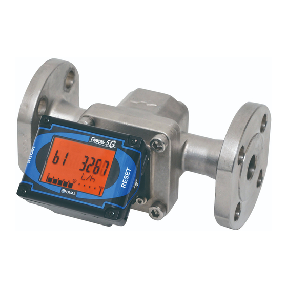
S-179-1-E 3.3 Part Names METER BODY REGISTER HIGH TEMP. MODEL LCD DISPLAY COOLING BLOCK ※ CABLE (1m LONG) (NOTE) Only external output equipped meters are furnished with the cable shown here with an asterisk ※ . -
Page 10: Piping
S-179-1-E 4. PIPING 4.1 Piping Precautions (1)Install the meter, exercising care to avoid pipe strains. (2)The meter should be installed downstream of the pump. (3)Provide a strainer upstream of the meter. (NOTE) The strainer net used is 80 mesh for nominal size 20mm and 60 mesh for sizes 25 through 50mm. (4)Install the pump taking into consideration the pressure loss of the entirre piping system. - Page 11 S-179-1-E ● Strainer Pressure Losses Pressure Loss kPa Model Kerosene 1.2mPa•s Heavy oil 19mPa•s LS5278A 6 ( 300 L/h) 50 (3800 L/h) LS5378A 7 ( 5 m 28 (6.4 m LS5578A 23 (11 m 26 ( 14 m LS5678A 25 (20 m 40 ( 24 m Strainer (6) Align the flow direction with the arrow mark on the meter body.
-
Page 12: Flushing The Piping Assembly
S-179-1-E 4.2 Flushing the Piping Assembly Be sure to remove the meter from the piping assembly and intall a short pipe section in place of the meter. Flushing the piping assembly with the meter in place will result in serious, costly damage to the meter ’... -
Page 13: Example Of Installations
S-179-1-E 4.4 Examples of Installation Vertical Line ● NOTE: Make pipe connections observing the instructions under the Install in the bypass side to pre- topic Piping Precautions on Section 4.1. “ ” vent scales falling from top of the piping assembly....standard piping Horizontal Line ●... - Page 14 S-179-1-E Example of Incorrect Piping How to prevent inductive interferences ● ● Do not install the meter in a position like this. ◎ Connect to the earth ground by using (Installation is correct if the measuring chamber is on a level one of the mounting bolts plane.)...
-
Page 15: How To Change The Flow Directions And Display Orientations
S-179-1-E 4.5 How to Change the Flow Directions and Display Orientations (1) How to change the flow directions The Flowpet is assembled to accept the flow from right to left. Flow directions can simply and readily be changed in the following manner: ARROW MARK (... - Page 16 S-179-1-E (2) How to change the register orientation The register display can be easily adjusted by click stop in 15 deg. increment to a desired direction for maximum viewability. The adjustable range is 150 deg. upward or downward. See the sketches below. 〈Tilted Downward (or Upward)〉...
-
Page 17: Wiring
S-179-1-E 5. WIRING In case of external output capability equipped models LS□□ 7 -5 , make electrical connections as follows. Also refer to the instruction manual for the receiving instrument (topic under Wiring Instructions ) to be used. “ ” 5.1 Field wiring (1) This flowmeter is furnished with 1 meter long cable (vinyl-sheathed, 4-conductor, individual elements AWG24). -
Page 18: Furnished Leads From The Meter
S-179-1-E 5.2 Furnished Leads from the Meter In case of an output capability equipped meter, 〈Wiring Nameplate〉 a shielded cable 1 meter long is furnished. Make ● Pulse output type electrical connections by referring to the wiring nameplate attached to the register. BROWN SUP. - Page 19 S-179-1-E ● ABOUT EXTERNAL POWER SOURCE IMPORTANT (1) The meter with external output capability can operate solely on the built-in battery. However, by supplying external power to leads BROWN and GREEN, it can work without consuming the battery. Also, even when the meter is operating on external power, do not remove the battery.
-
Page 20: Hook-Up Diagrams
S-179-1-E 5.3 Hook-up Diagrams (1) Flowpet-5G Output Circuitry BRO SUP. : Power + Pulse output type ● GRY SIG.1 : Factored pulse max.20mA 12 to 50V WHI SIG.2 : Unfactored pulse max. max.20mA max. GRN COM. : 0V NOTE: Leave the shielded wire open at its end (no contact). To extend the cable, make sure to use shielded wire and extend the shield as well. - Page 21 S-179-1-E (2) About load resistance of analog output 1900 specification In the analog 2-wire transmission system, power source cable is also used for signal wiring. Load resistance of analog output must be installed on the + side of the power. In addition, make sure that load resistance of the meter and leads are with in the operating range shown in the right figure.
-
Page 22: Display And Controls
S-179-1-E 6 DISPLAY AND CONTROLS 6.1 Display and Operation Buttons Left back: MODE button Right back: RESET button PUSH! Low battery alarm Units of registration (NOTE) About the Display Units The units of registration can be changed. L(std.), kL, m , g, kg, t, gal, ft , lb, /h, /min, (normal), none... -
Page 23: Display Capabilities And Operation
S-179-1-E 6.2 Display Capabilities and Operation (1) Register Because the register face can be changed to a desired direction in increments of 15 deg., there is virtually no limitation in choosing meter installation location. As to how to change the physical orientation, see Section 5. Built around a microprocessor, The register is capable of various display and pulse and analog signal output. - Page 24 S-179-1-E (5) Mode selector pushbutton Each time the “MODE” pushbutton is depressed, accumulated total, instantaneous flowrate (hourly and per-minute) and resettable total are displayed sequentially. (NOTE) Accumulated total 1. Depressing the MODE button to obtain an instantaneous flow rate while the meter is in operation, the internal counter keeps counting the flow for accumulated total.
- Page 25 S-179-1-E (6) About the Displayed Messages during Operation ② ① Prolonged operation Ordinary operation When MODE button is pressed, 8 bars appear. Held depressed ON without turning “OFF” immediately. Bars begin to disappear from the leftmost one. ⇒ Indicates a countdown before “prolonged depression” processing takes place.
-
Page 26: Operation
S-179-1-E 7. OPERATION 7.1 Operation (1) Read the information given on the nameplate before commencing operation and make sure to see the operating conditions conform to the specifications. Also make certain that meter installation, pipeline connections and electrical wiring have been made correctly. (2) Carefully follow the valve operations sequence given below. - Page 27 S-179-1-E METER VALVE LOW DIRECTION STRAINER BYPASS LINE (3) In applications where materials that tend to solidify are to be metered, lagging work is necessary. See Section 4.3 for lagging work. (4) The strainer net should be inspected and cleaned on a regular basis. On a newly installed piping assembly in particular, daily inspection of the net for condition is necessary, stretching the inspection intervals progressively to once in two or three days down according to the result of inspection.
-
Page 28: About Regiater S Life
S-179-1-E 7.2 About Register’ s Life Due to the life expectancy of electronic components, such as LCD device, and nonvolatile memory, the electronics in the register requires replacement as an assembly every 10 years approx. The life of electronics may possibly be more or less reduced, depending on the given environment in which the register is placed. -
Page 29: Troubleshooting
1. Remove the meter and remove the covers. over the inlet and outlet of flanges of the meter. 2. Oval rotors are jammed with scales and fail to rotate, 2. Separate the register, disassemble and clean the meter blocking the fluid flow. - Page 30 S-179-1-E ■ About Error messages In cases of improper situations, the 5G register displays error messages on the LCD as follows: Display Name Description Remedy Rewriting a parameter is attempted although the parameter Setting No.1 of SW3 of the display board PA.
- Page 31 S-179-1-E ■ Internal switches and test electrodes With the test electrodes (TP0 through TP4) inside the register, signal waveshape and internal voltage can be monitored. Internal PCB (FB board) ● Label Name Description Reference potential (0V) for Test electrode for monitoring TP0 (0V) monitoring waveshape and reference potential (0V)
-
Page 32: Disassembly And Inspection
S-179-1-E 9. DISASSEMBLY AND INSPECTION Althrough it depends on individual operating conditions, periodic disassembly and inspection every year is ◎ recommended. 〈Meter Body Disassembly and Inspection〉 ● MODEL LS4976, LS5076 1ST ROTOR REGISTER FRONT COVER 2ND ROTOR O-RING (1) Take off four hex bolts of the meter and separate (2) Holding the register and front cover, separate the register from the meter body. - Page 33 S-179-1-E ● MODEL LS5276, LS5376, LS5576, LS5676, LS5277, LS5377, LS5577, LS5677 《LS5276, LS5376, LS5277, LS5377》 Before disassembly, FRONT COVER mark match marks REGISTER with felt-tip pen. O-RING (1) Take off four hex bolts of the meter and separate 《LS5576, LS5676, LS5577, LS5677》 the register from the meter body.
- Page 34 S-179-1-E Precautions at Assembly — — Assembly is the reverse order of disassembly. Observe the following instructions: 〈LS4976, LS5076〉 (1) Assemble the rotors as shown in the sketch. Hand rotate more than one complete rotation to make sure of freely rotor rotation before installation. 1ST ROTOR MAGNET (2) Although identifying the 1st rotor from the 2nd is not required except for...
-
Page 35: Exploded View And Service Parts List
S-179-1-E 10. EXPRODED VIEW AND SERVICE PARTS LIST (1) Exploded View 1ST ROTOR (w/magnets) 2ND ROTOR High temp. model MODEL : LS4976-5□□ LS5076-5□□ LS5276-5□□ LS5376-5□□... -
Page 36: Service Part Lists
S-179-1-E (2) Service Parts List Assembly Name Part Name Quantity Remarks Basic Unit Basic Unit 1set Rotor Shaft Front Cover Front Cover 1st Rotor Rotors 1set with magnet ※ 2nd Rotor Bolts Hex Bolt, Front Cover O-Ring O-Ring Gasket, Register Cooling Block Iron Slag Register... -
Page 37: Battery Replacement And Parameter Setting Procedure
S-179-1-E 11. BATTERY REPLACEMENT AND PARAMETER SETTING PROCEDURE 11.1 Battery Replacement The lithium battery incorporated in the register is good for approximately eight years. (The battery life may be reduced more or less depending on the environmental conditions and other factors.) When the battery has run down, the low alarm icon “... - Page 38 S-179-1-E Battery pack replacement ① If using external power source, disconnect ② Pull out the battery pack and uncouple the the power first. Take off the four cross recess connector from the internal PC board by holding screws holding the register housing. Remove the lead wires close to the connector and the cover to access the internal PC board.
- Page 39 S-179-1-E BATTERY PACK Replacement battery packs are available at ● your nearest sales office. ③ Install a new battery pack in place: install it with its red wire lead on the “+”polarity side. Then carefully place the PC board back into its original position without jamming the lead wires between the housing and the PC board, and install the cover.
-
Page 40: Parameter Setting Procedure
S-179-1-E 11.2 Parameter Setting Procedure If you want to rewrite some parameters of the register, such as the unit of accumulated total, it is necessary that the parameters stored in the CPU be rewritten. If such is the case, rewrite parameters by the following procedure. - Page 41 S-179-1-E (2) Parameter List (1/2) (NOTE: Flow unit “L” written under “Description” in the following table refers to the standard setting.) • Total flow related data (Title Display: totAL) Symbol Parameter Description Remarks Example: Given meter factor 9.918mL/P (= 9.918 × 10 [L/P]) Meter factor Meter factor of the flowmeter (Unit: L/Pulse)
- Page 42 Set these parameters when performing loop test and etc. Start Simulated output Execute simulated output based on the conditions set for parameters S.b and S.c • Service mode (Title Display:88888888) NOTE: These parameters are for use by OVAL service personnel. Symbol Parameter Description Remarks I.Fr...
- Page 43 S-179-1-E (3) Parameter Setup Procedure With MODE and RESET buttons in the display, you can set up parameters. NOTES: A diagram to show parameter setup flow 1. For details of button opera- Parameter Measure Mode tion in steps ① ② ③...
- Page 44 S-179-1-E (4) Menu Trees and Button Operation : Holding the MODE button pressed for more than 2 seconds at this display changes the Review Mode to the Write Mode. The following operations are Accumulated total enabled in the Write Mode: None ①Pressing the MODE button moves the digit one place to the left.
- Page 45 S-179-1-E (5) The procedure to manually enter a parameter Switch operations sequence in "Parameter Setup Mode" comes in three ways (numerical setup, units setup, and decimal point setup) that follow: ① Numerical setup parameters (F, H, Pu, Pon, Af, AdAan, At, Example: Parameter: F (meter factor) A, A1d, A1H, A2d, A2H) Exponent sign (E: 10...
- Page 46 S-179-1-E ③ Item selection parameters (Un, d.o1, d.o2, A1S, A2S) In the parameter setup mode, the flickering part of a display indicates an item subject to change. … Each time MODE is pressed, the decimal point moves one place to the left (applicable only to A1S MODE and A2S).
- Page 47 S-179-1-E (6) Analog output trim procedure Analog output trimming (calibration of analog output characteristics) is performed at the time of shipment; there is no need to perform this procedure under normal circumstances. Example: 4mA trim procedure 【STEP1】Preparation ①Set up an ammeter (or voltmeter) to monitor analog output. Ammeter ○ DC Power 【STEP 4】Confirm trimmed 4mA output 【STEP 2】Begin 4mA simulated output ...
- Page 48 S-179-1-E (7) Simulated output function (LooPtESt) In the parameter review mode, simulated output can be performed by specifying "Instantaneous flow rate (S.b)" and "Total flow (S.c)" then executing "Start". Simulated output is calculated from parameters such as Meter factor, Pulse weight, Analog full scale, etc., based on "Instantaneous flow"...
- Page 49 S-179-1-E (8) About alarm output function (optional) 【Alarm related parameters and their meaning】 Parameter Symbol Parameter Description Alarm 1 Setting Alarm flow rate setting for Alarm output 1 (Set as per-hour flow rate) A 1 d □□□□□ Hysteresis for Alarm output 1 (Set as per-hour flow rate) A 1 H □□□□□...
-
Page 50: General Specifications
S-179-1-E 12. GENERAL SPECIFICATIONS low Range Nominal Dia. mm Oil Service L/h Water Service Meter Size Water Service Oil Service Kerosene Light Oil (A Heavy Oil) Heavy Oil — — 10 (20) to 800 7 (14) to 800 5 (10) to 800 —... -
Page 51: Register, Pulse Generator
S-179-1-E (3) Register, Pulse Generator Item Description ① Accumulated total flow (8-digit) ② Instantaneous flow rate, L/h (mode: b1) Display Selectable with MODE button ③ Instantaneous flow rate, L/min (mode: b2) ④ Resettable total flow (zero start/zero resettable, mode: C) (7-digit) ①... -
Page 52: Units Of Registration,Pulse Output Units Of Registration
S-179-1-E (4) Units of Registration, Pulse Output Units of Registration Factored Output Pulse Width Factored Output Pulse Unfactored Output Pulse Nominal Max. Total ○ : Selectable Application Model dia., mm Reading Pulse Unit Output freq. 1 ms 50 ms 100 ms 250 ms Meter Factor Output Freq. -
Page 53: Applicable En Standards
S-179-1-E (5) Applicable standards EMC Directive: 2014/30/EU Applicable EU Directive RoHS Directive: 2011/65/EU EMC Directive: EN61326-1: 2013 Class A Applicable EN standards, etc. RoHS Directive: EN50581: 2012 (NOTES ) 1. Output frequencies are those values at the maximum flowrate. 2. Hatched areas show setup options.(Unhatched area: Default at shipment from factory) 3. -
Page 54: Outline Dimensions
S-179-1-E 13. OUTLINE DIMENSIONS (1) FLOWPET-5G 82.5 FLOWPET- External output cable entry Register orientation (1m long cable furnished) adjustable in 15° steps (Covered with a blind plug for (75° upward, 75° downward) models without external output) Unit in:mm Dia., Nominal Weight L (※) -
Page 55: Strainer
S-179-1-E (2) Strainer Unit in:mm Model Nominal Dia. L (※) Weight, kg Net mesh Applicable Flowpet LS4976, LS5076 SS5278A LS5277 SS5378A LS5377, 5276 SS5578A LS5577, 5376, 5576 SS5678A LS5677, 5676 ※: In the case of JIS 10K RF flange. - Page 56 S-179-1-E 2017.06 Revised 2017.01 Revised 2016.03 Revised All specifications in this instruction manual are subject to change without notice for improvement 2015.11 Released in performance and product quality. S-179-1 -E (4) OVAL总代理: 上海洪柯自动化仪表有限公司 电话: 021-54485672 网址: WWW.SHAKIC.COM Email: shakic@163.com...
Need help?
Do you have a question about the Flowpet-5G Series and is the answer not in the manual?
Questions and answers