Table of Contents
Advertisement
Quick Links
Advertisement
Table of Contents
Troubleshooting

Related Manuals for Omron SYSMAC C200H-OV001


Summary of Contents for Omron SYSMAC C200H-OV001
- Page 1 Artisan Technology Group is your source for quality new and certified-used/pre-owned equipment SERVICE CENTER REPAIRS WE BUY USED EQUIPMENT • FAST SHIPPING AND DELIVERY Experienced engineers and technicians on staff Sell your excess, underutilized, and idle used equipment at our full-service, in-house repair center We also offer credit for buy-backs and trade-ins •...
- Page 2 Cat. No. W172-E1-2 SYSMAC C200H-OV001 Voice Unit Artisan Technology Group - Quality Instrumentation ... Guaranteed | (888) 88-SOURCE | www.artisantg.com...
- Page 3 C200H-OV001 Voice Unit Operation Manual Revised September 2000 Artisan Technology Group - Quality Instrumentation ... Guaranteed | (888) 88-SOURCE | www.artisantg.com...
- Page 4 OMRON. No patent liability is assumed with respect to the use of the information contained herein. Moreover, because OMRON is constantly striving to improve its high-quality products, the information contained in this manual is subject to change without notice.
- Page 5 About this Manual: This manual is an Operation Manual for OMRON’s C200H Voice Unit. The information included in this manual covers everything from system configuration and operation details to example PC programs suited to the Voice Unit’s wide range of uses. A brief description of the contents of this manual is as...
-
Page 6: Table Of Contents
TABLE OF CONTENTS PRECAUTIONS ..........Intended Audience . -
Page 7: Precautions
PRECAUTIONS This section provides general precautions for using the Programmable Controller (PC) and related devices. The information contained in this section is important for the safe and reliable application of the Programmable Con- troller. You must read this section and understand the information contained before attempting to set up or operate a PC system. -
Page 8: Intended Audience
It is extremely important that a PC and all PC Units be used for the specified purpose and under the specified conditions, especially in applications that can directly or indirectly affect human life. You must consult with your OMRON representative before applying a PC system to the above-mentioned applications. -
Page 9: Operating Environment Precautions
Application Precautions Operating Environment Precautions Caution Do not operate the control system in the following locations: Locations subject to direct sunlight. Locations subject to temperatures or humidity outside the range specified in the specifications. Locations subject to condensation as the result of severe changes in tempera- ture. - Page 10 Application Precautions Interlock circuits, limit circuits, and similar safety measures in external circuits (i.e., not in the Programmable Controller) must be provided by the customer. Always use the power supply voltages specified in this manual. An incorrect voltage may result in malfunction or burning. Take appropriate measures to ensure that the specified power with the rated voltage and frequency is supplied.
-
Page 11: Section 1 - Introduction
Introduction OMRON’s C200H Voice Unit is ideal for situations requiring voiced instructions or voiced warnings. The C200H Voice Unit allows the user to record up to 60 messages of varying length (64, 48, 32 through 00 seconds) and play them back as either individual complete messages (sentence mode) or intermixed (phrase mode) to form combined messages that vary with the control situation specified. -
Page 12: Nomenclature And Functions
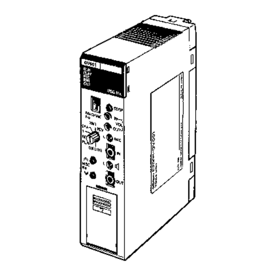
Section 1-1 Nomenclature and Functions Nomenclature and Functions Front Panel Artisan Technology Group - Quality Instrumentation ... Guaranteed | (888) 88-SOURCE | www.artisantg.com... - Page 13 Section 1-1 Nomenclature and Functions Battery Compartment Cover Removal Cover catch BATTERY To remove the battery compartment cover, slide the cover down in the direction indicated by the arrow. To attach the cover, push it up in the reverse direction, until the cover catch slides into place.
- Page 14 Section 1-1 Nomenclature and Functions Indicators Indicator Indication Conditions RUN (green) Lit if Unit is operating without error. Unlit when there is a PC communication error. PLAY (green) Lit during message playback or message erasure. Blinking (at 0.5 second intervals) indicates that REC or ERA mode is ready to operate.
- Page 15 Section 1-1 Nomenclature and Functions Switches, Controls, and Jacks Switches and controls Function MACHINE No. Sets the Voice Unit system configuration unit number to any integer between 0 and 9. Do not set the unit number to the same as that of another Special I/O Unit in the configuration.
- Page 16 Section 1-1 Nomenclature and Functions Back Panel DIP switch Mixing switch Backplane Connector DIP Switch Settings 1 2 3 4 5 6 Recording time Pin no. Function Message output mode 64 seconds 48 seconds Pin no. Function Setting 32 seconds Phrase combination mode Setting Unused...
-
Page 17: System Configuration
Section 1-2 System Configuration System Configuration C200H-OV001 Voice Unit C200H PC (Message output) Speaker Microphone (Message input) Amplifier Speaker Cassette tape recorder Optional RS-232C cable Length: 2 m Model no: C200H-CN224 Note The RS-232C port is located inside the battery compartment. Messages can be stored on floppy disk or PROM chip. -
Page 18: Input/Output Device Connections
CS1-series and The C200H-OV001 Voice Unit cannot be used with a CS1–series or C200HX/HG/HE(-Z) PCs C200HX/HG/HE(-Z) PC if an OMRON operator interface (Programmable Ter- minal) is connected to the peripheral port or RS-232C port via NT Link. Take the following countermeasures. - Page 19 Section 1-3 Input/Output Device Connections Microphone Recordings For microphone recordings set the L MIC selector switch to MIC and then connect the microphone to the message input jack using an unbalanced mini-plug (mini-plug dia. 3.5 mm). Tape Recorder Recordings For recordings on cassette tape, set the L MIC selector switch to L.
- Page 20 Section 1-3 Input/Output Device Connections Unbalanced Amplifier Connection Ç Ç Ç Ç Ç Ç É É É É É É Ç Ç Ç Ç Ç Ç É É É É É É Message Cable: single-conductor, shielded Unbalanced output MVVS (0.3 to 0.5 mm amplifier jack Cable length: 20 m max.
- Page 21 (shielded cable) Cable length: 2 m 6-pin connector 25-pin sub-D connector Plug: XM2A-2501 (OMRON) Housing: XM2S-2511 (OMRON) Note When connecting a peripheral device (PROM Writer etc.) to the Voice Unit, refer to the manual of the peripheral device for connection details.
-
Page 22: Section 2 - Data Area Allocation
SECTION 2 Data Area Allocation Data Areas ............Bit Number Allocation . -
Page 23: Data Areas
Section 2-2 Bit Number Allocation Data Areas The Voice Unit is allocated either 6 or 10 words (6 for sentence mode, 10 for phrase mode) of the PC’s IR area (word 100 through 199). For details on the IR area refer to the C200H operation manual. Message mode I/O area word allocation Sentence mode... - Page 24 Section 2-2 Bit Number Allocation 1 Sentence Mode Word Bit number Bit name Function 03 through 00 Number of These bits set the number of times a message is played repetitions back in one-shot operation mode. In level operation mode this bit has no function.
- Page 25 Section 2-2 Bit Number Allocation 2Phrase Combination Mode Word Bit number Bit name Function 03 through 00 Number of These bits set the number of times a message is played repetitions back in the one-shot operation mode. In level operation mode this bit has no function.
- Page 26 Section 2-2 Bit Number Allocation Word Bit number Bit name Function 15 through 08 11th phrase no. 07 through 00 12th phrase no. Output 15 through 08 13th phrase no. 07 through 00 14th phrase no. 15 through 08 15th phrase no. 07 through 00 16th phrase no.
-
Page 27: Section 3 - Operation
SECTION 3 Operation Preliminary Settings ..........Operating Procedure . -
Page 28: Preliminary Settings
Section 3-1 Preliminary Settings Preliminary Settings DIP Switch Setting Pin 1 Phrase combination mode Sentence mode Pin 2 One-shot operation Level operation Pin 3 Sequential mode Priority mode Pin 4 Be sure to set this switch to the OFF position. Pin 5 Pin 6 Recording time... -
Page 29: Operating Procedure
Section 3-2 Operating Procedure Operating Procedure Start Set the desired message out- put mode and recording time Refer to 3-1 Preliminary Settings . with the DIP switch on the back panel. If the Voice Unit is being used Refer to 3-5 ERASE Mode . for the first time, clear the memory using ERA mode. -
Page 30: Rec Mode
Section 3-3 REC Mode REC Mode Recording Procedure Start Connect an input device (micro- phone or tape recorder) to the Voice Unit. Set the line/microphone selec- tor switch according to the input device connected. Set the memory protect switch to the OFF position. Refer to 3-5 ERASE Mode . - Page 31 Section 3-3 REC Mode Input Device Connection A microphone or tape recorder can be connected to the Voice Unit. Using a microphone is simpler, however using a tape recorder improves the sound quality of the recorded message. When using a tape recorder, recording a signal sound (such as beep) to id- entify the beginning of the message is recommended.
- Page 32 Section 3-3 REC Mode Record messages Assign a message number to each of the recorded messages with the MSG No. increment and decrement switches. The message number allocated by these switches is displayed on the LED MSG No. display. Message numbers from 01 through 60 can be allocated.
-
Page 33: Play Mode
Section 3-4 PLAY Mode PLAY Mode Playing Back Messages in PLAY Mode Start Connect an output device (speaker or amplifier) to the Voice Unit. (A recorded mes- sage can also be monitored via the built-in speaker.) Set the line/speaker selector switch to match the connected output device. - Page 34 Section 3-4 PLAY Mode The PLAY indicator is blinking PLAY Mode at 0.5 second intervals when selector the Voice Unit is ready to play switch back. PLAY Playing back messages Specify the message to be played back with the MSG No. indicator display (LEDs) and the MSG No.
-
Page 35: Erase Mode
Section 3-5 ERASE Mode ERASE Mode Messages and displayed error codes can be erased in ERA mode. Erasing Messages Start Set the memory protect switch to the OFF position. Set the mode selector switch to ERA mode. To erase all messages To erase specified messages To erase error codes. - Page 36 Section 3-5 ERASE Mode MSG No. increment MSG No. indicator switch (00 through 60) MSG No. decrement switch Push the MSG No. increment/decre- ment switch to increment/decrement the displayed message number. Push the ST/SP switch. The PLAY and REC indicator will light, and the mes- sage indicated by the MSG No.
- Page 37 Section 3-5 ERASE Mode Mode selector switch Display in ERA mode. “00” PLAY is blinking on MSG No. indi- cator display (in this situa- tion the MSG No. cannot be incremented or decrem- ented). Voice Unit memory failure PLAY indicator display for modes other than ERA and RCV mode (the Voice Unit can- not operate in this state)
- Page 38 Section 3-5 ERASE Mode (Example) When message no. 6 is re- For memory failure sponsible for the memory fail- PLAY due to one message ure, “06” is blinking on the MSG No. indicator display. (At this time, the displayed mes- sage number cannot be changed.) (Example)
- Page 39 Section 3-5 ERASE Mode Note Do not change modes or turn OFF the power while a message is being erased. Doing so causes a message memory error. Message Erasing Time Erasing mode Maximum erasing time All messages Specified messages Note 1. The maximum time required to erase a specified message occurs when entire memory is used for messages 1 through 60 (i.e., when the mes- sages are recorded to the full extent of their recording time).
-
Page 40: Time Mode
Section 3-6 TIME Mode TIME Mode Displaying the Remaining Recording Time Start Set the mode selector to T. The remaining time is blinking on the MSG No. indicator dis- play. Checking the Remaining Set the mode selector to T (remaining time display mode). Time Mode selector... -
Page 41: Xmt/Rcv Mode
Section 3-7 XMT/RCV Mode XMT/RCV Mode Transmitting/Receiving Data to/from an External Device Start Connect an external device (FIT, etc.) to Voice Unit. (Transferring) (Receiving) Set the mode selector switch Set the memory protect to the XMT. switch to OFF. Set the mode selector switch Select a transfer mode (baud to RCV. - Page 42 Section 3-7 XMT/RCV Mode For connections to other external devices refer to the specifications of the external device. Voice Unit Communication Transfer format: Intel HEX Mode Particulars Baud rate: 2,400/4,800/9,600/19,200 bps (selectable) Control mode: RTS/CTS control, XON/XOFF control (valid/invalid) Bit format: 7 data bits, 2 stop bits, even parity RTS/CTS Signal Details Transfer (Voice Unit side) Data...
- Page 43 Section 3-7 XMT/RCV Mode The RTS signal turns OFF either when reception processing has been com- pleted or when the ST/SP switch is pushed again. Note Data transfer from the external device is enabled when the RTS signal of the Voice Unit is ON.
- Page 44 Section 3-7 XMT/RCV Mode (2) Select communication modes (displayed on the MSG no. indicator display) with the MSG no. increment/decrement switch. MSG No. increment switch MSG No. decrement switch MSG No. and communication mode (x10 digit) Baud rate (bps) XON/XOFF (yes/no) 2400 4800 9600...
- Page 45 Section 3-7 XMT/RCV Mode (Example) Ç Ç PLAY Display indication while data trans- Ç Ç fer is being executed in communica- tion mode “63” The data transfer is interrupted when the ST/SP switch is pushed. When transfer has finished, the Voice Unit enters transfer standby status. Data Receiving Method Select the communication mode required while in reception standby status and then push the ST/SP switch, which starts the transfer of data from an...
-
Page 46: On-Line Mode
Section 3-8 ON-LINE Mode When RCV mode is selected, the REC indicator is blinking at 0.2 second in- tervals. Mode selector PLAY Reception standby status With mode selector set to a position other than RCV and ERA Display of an error in the message PLAY memory for modes other than RCV and ERA (The Voice Unit cannot... - Page 47 Section 3-8 ON-LINE Mode In ON-LINE mode, any message or any combination of phrases stored in the memory can be selected and played back by the program. Display Indication during Message Playback Displays for sentence mode PLAY PLAY Display indication Display indication while message 5 is while message 5 is...
- Page 48 Section 3-8 ON-LINE Mode Sentence Mode Timing Diagrams Basic One-Shot Operation Message No. 1 output command Message No. 1 playback (The message is played back three times at 2 time time time second intervals.) Message playback in progress flag (word n+5 bit 02) The number of times a message is played back and the intervals at which message playback is repeated are recognized at the leading edge of the Message No.
- Page 49 Section 3-8 ON-LINE Mode Message No. 3 Message No. 2 Message No. 1 No. of repetitions = 2 No. of repetitions = 1 No. of repetitions = 1 Repeat interval = 2 s Repeat interval = 5 s Repeat interval = 5 s Message No.
- Page 50 Section 3-8 ON-LINE Mode Message No. 3 Message No. 2 Number of repetitions = 3 Number of repetitions = 2 Repeat interval = 3 s Repeat interval = 6 s Output command of Message no. 3 (played back 3 times) Output command of Message no.
- Page 51 Section 3-8 ON-LINE Mode message has been played back and the specified interval time has elapsed (point indicated in the figure), that message is repeatedly played back. The repeat interval is recognized when playback of a message has been completed (points A through D in the figure). The repeat interval specified at that time (2, 4, 2.5, or 5 seconds) first elapses before the next message is played back.
- Page 52 Section 3-8 ON-LINE Mode Level Operation in Priority Mode Message no. 3 output command Message no. 2 output command Interrupted Message no. 3 playback Message no. 2 playback 1.5 s Message output in progress flag (word n+5 bit 02) Of the messages whose output command have turned ON when one mes- sage has been played back and its interval time has elapsed, the message having the lowest message number is played back.
- Page 53 Section 3-8 ON-LINE Mode (Example) One-shot operation in sequential mode Message no. 5 output command (played back twice at 1 second intervals) Message no. 3 output command (played back once at 2 second intervals) Stop command (word n+1 bit 00) 2nd time Interrupted Message no.
- Page 54 Section 3-8 ON-LINE Mode Scan time C200H PC Instruction execution refresh refresh refresh refresh Data for words Data for word n+5 n through n+4 Voice Unit IN refresh (Voice Unit OUT refresh (PC Voice Unit) ON-LINE flag Number of playback repetitions Message output in progress flag Repeat interval Output message area FULL flag...
- Page 55 Section 3-8 ON-LINE Mode One-shot operation in sequential mode Message area during playback Message area during playback No. 3 No. 10 Message no. 3 has been played back. Output message area Output message area (FULL status) No. 10 No. 1 Messages are stored in No.
- Page 56 Section 3-8 ON-LINE Mode I/O refresh C200H PC OUT IN OUT IN OUT IN OUT IN Output mes- sage area FULL (word n+5 bit 03) The number of messages The number of messages stored in stored in the area reaches 20. the area decreases to 19 or less.
- Page 57 Section 3-8 ON-LINE Mode input refreshing, if the battery has been connected correctly or if a new bat- tery has been connected. In Phrase Combination Mode Basic Message Playback In the following example, phrase no. 5, 18, and 36 are combined. These Timing phrases are played back in this order twice at 5 second intervals.
- Page 58 Section 3-8 ON-LINE Mode When More Than One Output Command Turns ON Phrase Combination Number of repetitions Repeat intervals Priority command Message no. 1 Phrase nos. 1, 5, and 2 2 times Message no. 2 Phrase nos. 3, 6, 4, and 2 3 times Message no.
- Page 59 Section 3-8 ON-LINE Mode The messages stored in memory are retained even when the stop command turns ON, and are played back when the command turns OFF. Stop Command (word n bit 15) Message no. 1 output command (played back twice at 1 sec- ond intervals) Message no.
- Page 60 Section 3-8 ON-LINE Mode Execution Command Transfers the number of repeti- tions and repeat intervals for message playback and the data of the priority command to the Voice Unit. Transfers the phrase numbers to the Voice Unit. Turns ON the message output command bit.
- Page 61 Section 3-8 ON-LINE Mode Voice Unit busy flag (word n+9 bit 01) (valid in ON-LINE mode only) This flag turns ON when output refreshing is executed and the ON status of an output command is recognized, and when subsequent input refreshing in the same I/O refresh area is executed.
- Page 62 Section 3-8 ON-LINE Mode The output command of mes- sage no. 22, whose priority com- Message area during playback Message area during playback mand has turned ON, turns ON. Message No. 1 Message no. 22 Output message area (FULL status) Output message area (FULL status) Message no.
- Page 63 Section 3-8 ON-LINE Mode Voice Unit error flag (word n+9 bit 04) In modes other than ON-LINE mode: This flag performs the same operations as that of the ERR indicator. For in- formation on the ERR indicator, refer to 5-1 Error Codes . This paragraph should be an introduction to the level-1 section briefly ex- plaining the contents and purpose of the section.
-
Page 64: Operations In On-Line Mode
Section 3-9 Operations in ON-LINE Mode Operations in ON-LINE Mode Message Output Modes The following diagram shows the various options for the Message output mode during ON-LINE mode operation. Repeat function Sequential mode Stop function One-shot operation Repeat function Priority mode Sentence mode Stop function Sequential mode... -
Page 65: Mixing Function
Section 3-10 Mixing Function Phrase Combination Mode In this mode, a message is constructed of several phrases which have been programmed in advance. Phrase set combinations and the sequence in which the phrase sets are played back (as one message) are program con- trolled. - Page 66 Section 3-10 Mixing Function Sharing one speaker with several Voice Units Voice Units Speaker No. 1 No. 2 No. 3 In the above diagram the speaker output a message which is a mixture of the messages of the Voice Unit 1 through3. To interconnect two or more Voice Units connect the message output jack of one Voice Unit to the message input jack of another.
-
Page 67: Section 4 - Example Programs
SECTION 4 Example Programs Sentence Mode Example Programs ........Phrase Combination Mode Example Programs . -
Page 68: Sentence Mode Example Programs
Section 4-1 Sentence Mode Example Programs Sentence Mode Example Programs This section describes how to develop PC programs for Voice Unit message playback when the Voice Unit is under PC control (ON-LINE mode). For the following programs it is assumed that the Voice Unit has been mounted on the PC as follows: C200H Input Unit: word 1... - Page 69 Section 4-1 Sentence Mode Example Programs Message no. 1 is played back when input 00100 turns ON. Message no. 3 is played back when input 00101 turns ON. Message playback is interrupted while input 00102 is ON. The number of repetitions and interval times of each Message no. are as fol- lows: Message no.
- Page 70 Section 4-1 Sentence Mode Example Programs Message no. 18 Message no. 32 Number of repetitions 4 times 6 times Repeat intervals 1.5 s 2.5 s 00100 DIFU 03000 03000 In this section, MOV transfers repetition (4 times) and interval data (1.5 s) to the #0154 Voice Unit when input 00100 turns ON.
- Page 71 Section 4-1 Sentence Mode Example Programs 00100 DIFU 03000 In this section while TIM00 is OFF (time not up) the ON status of input 03000 TIM000 00100 is maintained. During this time 03001 the transfer of data and message no. 9’s output command to the Voice Unit occurs.
- Page 72 Section 4-1 Sentence Mode Example Programs The number of repetitions and repeat intervals are as follows: Message no. 12 Message no. 7 Message no. 25 Number of repetitions 3 times Continuously 5 times Repeat intervals 0.2 s 0.5 s 1.0 s 00100 11503 In this program, if two or more...
-
Page 73: Phrase Combination Mode Example Programs
Section 4-2 Phrase Combination Mode Example Programs Message playback is stopped while input 00102 is ON. The messages are played back at 0.5 second intervals. 25313 This command transfers a constant #0050 interval time of 0.5 second to the Voice Unit. 00100 This command issues the output 11201... - Page 74 Section 4-2 Phrase Combination Mode Example Programs The following phrases are assigned to each Phrase no.: Phrase no. 5 = “Unit 5” Phrase no. 7 = “Unit 7” Phrase no. 17 = “Requires” Phrase no. 31 = “Materials” Note If the number of phrases used is less than 16, set the last Phrase no. to “00”. 00100 This command transfers repetition (3 @MOV...
- Page 75 Section 4-2 Phrase Combination Mode Example Programs When input 00100 turns ON, the message “Unit 5 requires materials” is is- sued three times at 0.3 second intervals. When input 00101 turns ON, the message “Unit 7 requires materials” is issued three times at 0.3 second inter- vals.
- Page 76 Section 4-2 Phrase Combination Mode Example Programs 00100 This command transfers repetition (2 @MOV times) and interval data (1.0 s) to the #0102 Voice Unit (when input 00100 turns ON). This command sets Phrase no. 2 as @MOV the first phrase and Phrase no. 20 as #0220 the second phrase (when input 00100 turns ON).
- Page 77 Section 4-2 Phrase Combination Mode Example Programs Example 3: In the following program, phrases are registered in the read-only DM area (DMs 1000 through 1999). Register the following data in the DM area (starting from DM 1000) via the Programming Console: Phrase Combination Number of playback Repeat...
- Page 78 Section 4-2 Phrase Combination Mode Example Programs Note In the above program, when two inputs turn ON during the same scan time, only the data of the latter part of the program is output. To avoid this, use a program like the one shown in Example 4. Example 4: In the following example, the output commands of two or more messages turn ON within two scan repetitions.
- Page 79 Section 4-2 Phrase Combination Mode Example Programs 00100 DIFU 03000 00101 DIFU 03001 03000 03004 03002 03002 03001 03005 03003 03003 03002 12901 This command transfers the combi- nation of Phrase nos. 1 and 10 to #0052 the Voice Unit when the Voice Unit busy flag (12901) is OFF.
- Page 80 Section 4-2 Phrase Combination Mode Example Programs Example 5: In the following example, the Voice Unit is mounted on a Remote I/O Slave Rack. Note The Voice Unit may not operate correctly if the Remote I/O transfer time is longer than the PC’s scan time and a differential instruction is used in the program.
- Page 81 Section 4-2 Phrase Combination Mode Example Programs Example 6: In the following example, the output message area becomes full. Phrase nos. 20, 7, and 11 are combined and played back twice at 3.0 second intervals when input 00100 turns ON. 00100 This command maintains the ON DIFU...
- Page 82 Section 4-2 Phrase Combination Mode Example Programs 00100 03004 12901 12903 03006 DIFU 03000 00101 #0025 DIFU 03001 00102 #1006 DIFU 03002 #3800 03000 03006 03003 03003 03007 03007 03001 03004 03005 12901 12903 03006 03007 03004 #0106 03008 03002 03005 03005 #0948...
- Page 83 Section 4-2 Phrase Combination Mode Example Programs It is assumed that the Voice Units are mounted on the CPU Backplane as follows (for connection details refer to 3-10 Mixing Function ). One speaker shared C200H by two Voice Units. Voice Unit 1 Voice Unit 2 Input Unit: Word 0 When input 00100 turns ON, Phrase nos.
- Page 84 Section 4-2 Phrase Combination Mode Example Programs 00100 This command transfers the data @MOV of the combined phrases to Voice #0001 Unit 1 when input 00100 turns ON. @MOV #0511 @MOV #0000 DIFU 11014 00100 Differentiation of input 00100 DIFU 03000 12014 03000...
- Page 85 Section 4-2 Phrase Combination Mode Example Programs To use an I/O refresh instruction, confirm that at least 3 ms elapse between I/O refresh operations; otherwise, the output command of a message may not be input to the Voice Unit. Ordinary I/O refresh 3 ms min.
-
Page 86: Section 5 - Troubleshooting
SECTION 5 Troubleshooting Error Codes ............Troubleshooting . -
Page 87: Error Codes
Section 5-1 Error Codes Error Codes If an error occurs in the Voice Unit the ERR indicator on the front panel is lit or blinking. The following table lists error indications and error codes which may be displayed on the MSG No. indicator. Error indications for all modes Error indication Display... - Page 88 Section 5-1 Error Codes Errors in REC mode Display Possible Cause Correction A different recording time has been Match the recording time of the specified (by the DIP switch on the message data (recorded message) with PLAY back panel). the recording time set by the DIP switch on the back panel.
- Page 89 Section 5-1 Error Codes Errors in PLAY mode Display Possible Cause Correction No message is recorded (in this Check that the message is being situation the error indication is made recorded in REC mode, or written in PLAY when the mode selector switch is RCV mode.
- Page 90 Section 5-1 Error Codes Errors in ERA mode Display Possible Cause Correction The memory protect switch is ON (in Turn OFF the memory protect switch this situation the error indication is and press the ST/SP switch. PLAY made when the mode selector switch is operated or when the ST/SP switch is pressed).
- Page 91 Section 5-1 Error Codes Display Possible Cause Correction A message memory error (2) occurs Turn OFF the memory protect switch with the memory protect switch ON (in and press the ST/SP switch to clear the PLAY this situation the error indication is error code(s) displayed on the LED made when the mode selector switch is display.
-
Page 92: Troubleshooting
Section 5-2 Troubleshooting Errors in RCV mode Display Possible Cause Correction The memory protect switch is ON (in Turn OFF the memory protect switch this situation the error indication is and start reception. PLAY made when the mode selector switch is operated or when the ST/SP switch is pressed). - Page 93 Section 5-2 Troubleshooting Playback Error Possible Cause Correction A Message is not played back The output volume control is at the Adjust the volume by turning the MIN. position (when a speaker is output volume control clockwise used). toward the MAX. position. Pin 4 of the DIP switches on the back Turn OFF the power to the PC, panel of the Voice Unit is ON.
-
Page 94: Appendix
Appendix A Inspection and Maintenance Inspection Items Periodically inspect the following items: Item Particulars Normal Operating Criteria Remarks Environmental Is the ambient operating temperature 0 to 55 C Thermometer conditions (temperature inside the control box) appropriate? Is ambient operating humidity (humidity 35 to 85% (without condensation) Hygrometer inside the control box) appropriate? - Page 95 Inspection and Maintainance Appendix A Catch (Fig. 1) BATTERY BATTERY Push the cover down. Battery cover Mounting hole (Fig. 2) Battery holder Battery connector Battery set C200H-BAT09 Notes on Handling When replacing the Unit, be sure to turn OFF the power first. After replacing the old Unit with a new one, check again to ensure the new Unit is normal.
-
Page 96: B - Specifications
Appendix B Specifications Item Specifications Voice synthesis method Adaptive Differential Pulse-Coded Modulation (ADPCM) Message recording time 32/48/64 seconds (switch selectable) Message capacity 60 max. (sentences and phrases) Microphone input: unbalanced dynamic microphone (600 Ω) Message input MIC IN (switch-selectable) LINE IN Tape input: Input impedance: 50 kΩ, unbalanced;... - Page 97 Specifications Appendix B Dimensions 130 mm 35 mm 100.5 mm When mounted to a Rack Backplane Message input plug Message output plug 117 mm Approx. 180 mm The depth of the Voice Unit itself measures 100.5 mm. However, when the Unit is mounted on a Backplane and when connectors are connected to the Unit, the total depth increases to about 180 mm.
-
Page 98: C - Standard Models
Appendix C Standard Models Name Description Model Voice Unit C200H-OV001 Battery set Backup battery for C200H C200H-BAT09 RS-232C cable 6-to-25-pin conversion C200H-CN224 Cable length: 2 m For C200H Voice Unit Artisan Technology Group - Quality Instrumentation ... Guaranteed | (888) 88-SOURCE | www.artisantg.com... -
Page 99: Glossary
Unit In OMRON PC terminology, the word Unit is capitalized to indicate any prod- uct sold for a PC System. though most of the names of these products end with the word Unit, not all do, e.g., a Remote Terminal is referred to in a col-... - Page 100 Glossary lective sense as a Unit. Context generally makes any limitations of this word clear. word In digital circuits, a group of bits. Usually a word consists of four, eight, or sixteen bits. In C-series PCs, a word consists of sixteen bits. Words can be used to store data, or they can be used for I/O.
-
Page 101: Index
Index Symbols LEDs and Indicators, 4 **Empty**, 69 Limits on Remote I/O Slave Rack Mounting, 8 LPF (Lowpass filter) Selection Function, 89 applications, precautions, ix Maintenance and Inspection, 87 Memory Protect Switch, 3 , 20 Message Data Transfer/Reception Time, 37 , 38 Back Panel, 6 Message Erasing Time, 31 Balanced Amplifier Connection, 10... - Page 102 Index Standard Models, 91 Unit No. Setting Switch, 20 Switches, Controls, and Jacks, 5 system Configuration, 7 Voice Unit Operation via the Program, 38 Tape Recorder Recordings, 9 Timing Diagrams, 40 Wiring, 10 Unbalanced Amplifier Connection, 10 Artisan Technology Group - Quality Instrumentation ... Guaranteed | (888) 88-SOURCE | www.artisantg.com...
- Page 103 Artisan Technology Group is your source for quality new and certified-used/pre-owned equipment SERVICE CENTER REPAIRS WE BUY USED EQUIPMENT • FAST SHIPPING AND DELIVERY Experienced engineers and technicians on staff Sell your excess, underutilized, and idle used equipment at our full-service, in-house repair center We also offer credit for buy-backs and trade-ins •...
Need help?
Do you have a question about the SYSMAC C200H-OV001 and is the answer not in the manual?
Questions and answers