Omron C200H Series Replacement Manual
From c200h to cs1
Hide thumbs
Also See for C200H Series:
- Replacement manual (36 pages) ,
- Replacement manual from c200h to cs (36 pages) ,
- Installation manual (161 pages)
Advertisement
Advertisement
Table of Contents

Related Manuals for Omron C200H Series


Summary of Contents for Omron C200H Series
- Page 1 C200H Replacement Guide From C200H to CS1...
- Page 2 About this document This document provides the reference information for replacing C200H PLC systems with CS1 series PLC. This document does not include precautions and reminders ;please read and understand the important precautions and reminders described on the manuals of PLCs (both of PLC used in the existing system and PLC you will use to replace the existing PLC) before attempting to start operation.
- Page 3 Related Manuals CPU Units Man.No. Model Manual W394 CS1G/H-CPU□□H CS/CJ/NSJ Series PROGRAMMING MANUAL CS1G/H-CPU□□-V1 CS1D-CPU□□H CS1D-CPU□□S CJ1H-CPU□□H-R CJ1G/H-CPU□□H CJ1G-CPU□□P CJ1M/G-CPU□□ NSJ□-□□□□(B)-□□□ W474 CS1G/H-CPU□□H CS/CJ/NSJ Series INSTRUCTIONS REFERENCE MANUAL CS1G/H-CPU□□-V1 CS1D-CPU□□H CS1D-CPU□□S CJ1H-CPU□□H-R CJ1G/H-CPU□□H CJ1G-CPU□□P CJ1M/G-CPU□□ NSJ□-□□□□(B)-□□□ W342 CS1G/H-CPU□□H CS/CJ/CP/NSJ Series Communications Commands REFERENCE MANUAL CS1G/H-CPU□□-V1 CS1D-CPU□□H CS1D-CPU□□S...
- Page 4 Special I/O Units Man.No. Model Manual W426 CS1W-NC□71 CS/CJ Series Position Control Units OPERATION MANUAL CJ1W-NC□71(-MA) W435 CS1W-MCH71 CS/CJ series Motion Control Units OPERATION MANUAL CJ1W-MCH71 W440 CS1W-FLN22 CS/CJ Series FL-net Units OPERATION MANUAL CJ1W-FLN22(100BASE-TX) W336 CS1W-SCB□□-V1 CS/CJ Series Serial Communications Boards Serial Communications Units CS1W-SCU□□-V1 OPERATION MANUAL CJ1W-SCU□□-V1...
- Page 5 Man.No. Model Manual W304 C200HW-COM01 C200HW Communication Boards OPERATION MANUAL C200HW-COM02-V1 to C200HW-COM06-EV1 W257 CVM1-PRS71 Teaching Box OPERATION MANUAL Network Communications Units Man.No. Model Manual W309 CS1W-CLK23 Controller Link Units OPERATION MANUAL CS1W-CLK21-V1 CJ1W-CLK23 CJ1W-CLK21-V1 C200HW-CLK21 CVM1-CLK21 CQM1H-CLK21 CS1W-RPT0□ W370 CS1W-CLK13 Optical Ring Controller Link Units OPERATION MANUAL CS1W-CLK12-V1...
- Page 6 Man.No. Model Manual W120 C500-RM201/RT201 C series Rack PCs Wired Remote I/O SYSTEM MANUAL C200H-RM201/RT201/202 G71-IC16/OD16 G72C-ID16/OD16 S32-RS1 W379 CVM1-DRM21-V1 DeviceNet Master Units OPERATION MANUAL C200HW-DRM21-V1 W347 C200HW-DRT21 DeviceNet Slaves OPERATION MANUAL CQM1-DRT21 DRT1 W135 C200H-LK401 C Series PC Link SYSTEM MANUAL C500-LK009-V1 Support Software Man.No.
- Page 7 WHETHER SUCH CLAIM IS BASED ON CONTRACT, WARRANTY, NEGLIGENCE, OR STRICT LIABILITY. In no event shall the responsibility of OMRON for any act exceed the individual price of the product on which liability is asserted. IN NO EVENT SHALL OMRON BE RESPONSIBLE FOR WARRANTY, REPAIR, OR OTHER CLAIMS...
- Page 8 Performance data given in this manual is provided as a guide for the user in determining suitability and does not constitute a warranty. It may represent the result of OMRON's test conditions, and the users must correlate it to actual application requirements. Actual performance is subject to the OMRON Warranty and Limitations of Liability.
- Page 9 Application Considerations SUITABILITY FOR USE OMRON shall not be responsible for conformity with any standards, codes, or regulations that apply to the combination of products in the customer's application or use of the products. At the customer's request, OMRON will provide applicable third party certification documents identifying ratings and limitations of use that apply to the products.
- Page 10 MEMO...
-
Page 11: Table Of Contents
C200H Replacement Guide From C200H to CS1 Table of Contents Work flow................................2 Selecting the model...............................3 Reading data from C200H ............................7 Converting the program for CS1 ...........................9 Writing data to CS1 .............................11 Appendix ................................13 Appendix A. Instructions converted by Change Model on CX-Programmer ............13 Appendix B. -
Page 12: Work Flow
This replacement guide describes the procedure to rebuild the system which uses the C200H-series PLC by introducing the CS1-series PLC instead. The CS-series has functions which can replace the functions and operation of C200H-series PLC. Take the below work flow to replace your system. Also, refer to the reference pages for details. -
Page 13: Selecting The Model
Selecting the model Outline of the system configuration CX-Programmer SYSMAC Support Software CX-Programmer C200H Expansion Backplanes Expansion Backplanes The table below lists the models of C200H-series and each corresponding models of CS1-series. Select the CS1-series model which is compatible with the C200H-series model. Or, select the CS1-series model with similar specification to the C200H-series Unit. - Page 14 Memory Cassette Unit name C200H-series CS1-series Description Memory Unit Memory Unit (RAM type) None The CS Series CPU Units have a nonvolatile C200H-MR431 memory for user program in it. The memory (Battery type) unit is unnecessary. C200H-MR432 They also have the clock function. (Capacitor type) C200H-MR831 (Battery type)
- Page 15 <I/O Units, CPU Bus Units> Unit name C200H-series CS1-series Description Basic I/O Units C200H-I□□□ C200H-I□□□ C200H-series Basic I/O Units can be used C200H-O□□□ C200H-O□□□ with CS1-series CPU Units. C200H-M□□□ C200H-M□□□ Refer to Appendix E. Table of Input/Output Units for CS1 Basic Input/Output Units CS1W-I□□□...
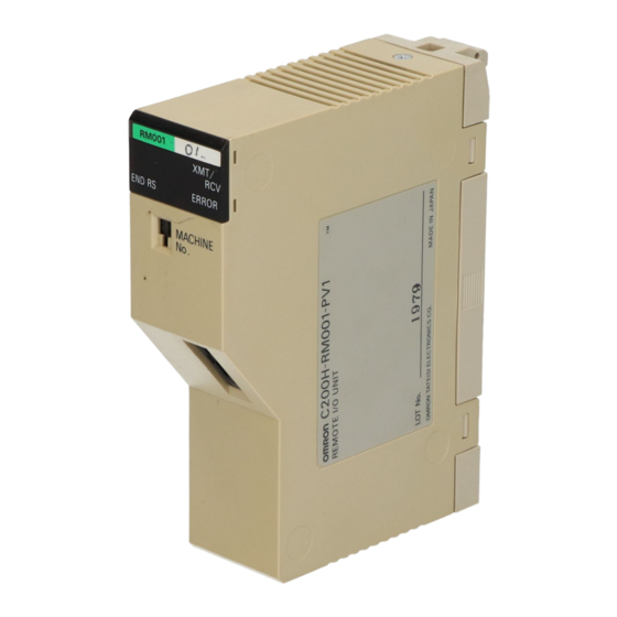
- Page 16 Unit name C200H-series CS1-series Description Communication Units [SYSBUS] [SYSBUS] SYSBUS Unit can be used with CS1-series Wire type:C200H-RM201 Wire type: C200H-RM201 CPU Unit. However, relay area allocation, Optical Fiber Cable type: Optical Fiber Cable type: etc. must be modified. C200H-RM001-PV1 C200H-RM001-PV1 [CompoNet] To improve the system performance and to...
-
Page 17: Reading Data From C200H
(1) Attach the Peripheral Interface Unit onto the C200H and connect it with a PC. (2) Start up the CX-Programmer. (On the Start menu, select All Program - OMRON - CX-One - CX-Programmer - CX-Programmer.) (3) Select C200H for the Device Type. (Select File - New to display below dialog). - Page 18 (4) Connect the PLC and the CX-Programmer online. (Select PLC - Work Online). (5) Transfer the ladder program and I/O table. (Select PLC - Transfer - From PLC.) Press the OK button to start transfer. (6) Transfer the PLC memory data (Data Memory). (Select PLC on the menu bar and then click Edit - Memory.) Scroll and check all the areas.
-
Page 19: Converting The Program For Cs1
Converting the program for CS1 On the CX-Programmer, convert the program for CS1. (1) Start the CX-Programmer and open the program file for C200H. (Select File - Open.) (2) Change the Device Type from C200H to CS1. (Select PLC - Change Model to display below dialog.) (3) The instructions are automatically converted. - Page 20 by Change Model on CX-Programmer. You can check the program by selecting Program - Compile (Program Check). The Output Window shows the checking results. (4) The PLC memory data cannot be maintained when PLC model is changed. Open the PLC Memory window for both C200H and CS-series PLCs and copy and paste the necessary memory data after conversion.
-
Page 21: Writing Data To Cs1
Writing data to CS1 Transfer the converted and modified program, PLC settings and Data Memory to the CS1. Required items Support software CX-One (PC) CXONE-AL□□C-V□/ AL□□D-V□ (CX-Programmer) Connecting cable CS1W-CN226/626 CX-Programmer Connecting cable CS1W-CN226/626 Peripheral port on CPU Unit (1) Connect the CS1 and the PC. (2) Start the CX-Programmer and open the converted program file. - Page 22 (5) Select PLC on the menu bar and then click Edit - Memory to display below dialog. Transfer the PLC memory (Data Memory: D and Holding Relay: HR) after selecting the transfer data. Click the Transfer to PLC button. (6) Make the CX-Programmer offline.
-
Page 23: Appendix
Appendix Appendix A. Instructions converted by Change Model on CX-Programmer (1) The data type of operand is changed from BCD data to BIN data for some instructions. (2) The number of operand is changed for some instructions. (3) Interrupt control instructions must be changed. (Use MSKS, MSKR, CLI, DI, and EI). Refer to the list below for detail. -
Page 24: Appendix B. Change Of Unit Area Allocation
Appendix B. Change of unit area allocation This section describes the difference of unit area allocation in C200H and CS1-series. Refer to related manuals for details. Item C200H-series CS1-series Description I/O allocation "Free location and fixed channel" "Free location and free channel" CS1-series, Basic I/O Change the channel and bit address... -
Page 25: Appendix E. Table Of Input/Output Units
Appendix E. Table of Input/Output Units - Input Unit (1)If different terminal block or connector is used, you have to change the wiring. (2)If the input circuit specification is not the same, check if there is no problem in operation. (3)If the number of circuit is different (increased), wire and connect the terminals and each common terminals. - Page 26 <TTL Input Unit> C200H-series Unit Corresponding CS-series Unit Description Difference C200H-ID501 No replacement model TTL Input Unit with connector for 32 inputs. The CS-series does not have the same type of Unit. 5VDC, 3.5mA, Connector, 32 Use the C200H-ID501 with CS1, or use 24VDC Input Unit (CS1W-ID231) or inputs (Special I/O Unit) TTL Input/Output Unit (CS1W-MD561) instead.
- Page 27 ■ Output Unit (1) If different terminal block or connector is used, you have to change the wiring. (2) If the number of circuit is different (increased), wire and connect the terminals and each common terminals. (3) If the output specification is not same, check if there is no problem in operation. (4) The relay lifetime might change depending on the usage, when the used relay is different.
- Page 28 <Relay Output Units> C200H-series Unit Corresponding CS-series Unit Description Difference C200H-OC225 CS1W-OC211 Relay Output Units with 1) Terminal block terminal block for 16 outputs. 2) Number of circuit (16 points/common x1 250VAC/24VDC, 2A, 250VAC/120VDC, 2A, Terminal circuit ->8 points/common x2 circuits) Terminal block, 16 outputs block, 16 outputs 3) Output circuit specification...
- Page 29 <Transistor Output Units> C200H-series Unit Corresponding CS-series Unit Description Difference C200H-OD217 CS1W-OD212 Transistor Output Units with 1) Terminal block terminal block for 12 outputs. 2) Output points (12-> 16 points) 24 VDC, 0.3A, Sourcing, 12-24 VDC, 0.5A, Sourcing, Replace this unit with a 3) Number of circuit (12 points/common x1 Terminal block, 12 outputs Terminal block, load short circuit...
- Page 30 <Transistor Output Units> C200H-series Unit Corresponding CS-series Unit Description Difference C200H-OD219 CS1W-OD261 Transistor Output Units with 1) Number of circuit (32 points/common x2 connector for 64 outputs.. circuit ->16 points/common x4 circuits) 4.5 to 26.3 VDC, Sinking, 12-24 VDC, 0.3A, Sinking, 2) Output circuit specification 0.1A, Connector, 64 outputs Connector, 64 outputs...
- Page 31 ■Input/Output Units (1) The CS-series has two Input/Output Units: CS1W-MD261 and MD561. The unit area allocation is different from C200H-series input/output units, since the number of input/output of CS-series unit is 32 points each. (2) C200H-series Units can be used with CS1-series CPU Unit. (3) Refer to related manuals for details, even if functions of C200H-series are supported by CS1-series Units, since a part of specifications may differ.
- Page 32 2010-2011 P069-E1-03 0611(1210)
Need help?
Do you have a question about the C200H Series and is the answer not in the manual?
Questions and answers