
Related Manuals for Omron SYSMAC C200H CPU11-E


Summarization of Contents
INSTALLATION GUIDE
Section 1 Introduction
Provides general information about Programmable Controllers and their role in control systems.
1-1 What is a Control System?
Basic definition of a control system and its components.
1-2 The Role of the PC
Explains the function of a Programmable Controller in a manufacturing process.
1-3 How Does a PC Work?
Overview of PC operational principles, cycle time, and internal operations.
Section 2 Description
Details the individual units that comprise a PC system.
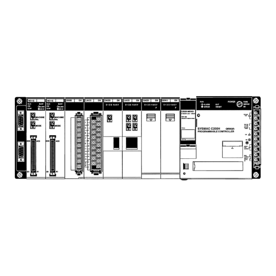
2-1 CPU Rack
Details the components and layout of a CPU Rack.
2-2 CPU
Describes the different CPU models and their features.
2-3 Expansion I/O Rack
Explains the structure and purpose of an Expansion I/O Rack.
2-4 Power Supply
Details the AC and DC power supply units for the system.
2-5 I/O Units
Describes the different shapes and features of I/O Units.
2-6 Memory Units
Covers the types of memory units available and their functions.
Section 3 Assembly Instructions
Provides guidance on assembling the PC system components.
3-1 Mounting the Units
Step-by-step guide on mounting system components to the backplane.
3-2 Memory Packs
Instructions for mounting EPROM chips to memory packs.
3-3 System Configurations
Overview of possible system configurations and component placement.
Section 4 System Connections
Details considerations for making PC system connections.
4-1 IR Word Allocation
Explains how I/O points are allocated to hardware word numbers.
4-2 Remote I/O
Discusses extending system distance using Remote I/O systems.
4-3 Maximum Current and Power Supplied
Details power supply limitations and calculation examples.
4-4 I/O Connections
Provides guidance on connecting I/O devices to I/O Units.
Section 5 Installation Environment
Details the necessary environment and conditions for PC installation.
5-1 Installation Environment
Specifies ambient conditions and cooling requirements for proper operation.
5-2 Mounting Requirements
Details vertical mounting and DIN rail installation procedures.
5-3 Duct Work
Guidelines for separating power and control cables in ducts.
5-4 Preventing Noise
Recommendations for minimizing electrical noise interference.
Section 6 Power Considerations
Covers important aspects of PC power supply and distribution.
6-1 Grounding
Explains proper grounding procedures for electrical safety.
6-2 Insulation
Notes the use of insulating plates for separate racks.
6-3 Emergency Stop
Details the implementation of an external emergency stop circuit.
6-4 Wiring
Shows correct wiring methods for power source connections.
Section 7 Safety Considerations
Highlights safety requirements during PC installation and operation.
7-1 Interlock Circuits
Describes using interlock circuits to prevent simultaneous outputs.
7-2 Wiring
Discusses input leakage current and output protection wiring.
PRECAUTIONS
1 Intended Audience
Identifies the target audience for this manual.
2 General Precautions
Provides general advice for operating the product safely.
3 Safety Precautions
Lists critical safety warnings to prevent injury or damage.
4 Operating Environment Precautions
Advises on suitable operating environments and potential hazards.
5 Application Precautions
Outlines precautions for safe and proper application of the system.
Appendix A Inspection and Maintenance
CPU and Power Supply Fuses
Instructions for replacing CPU and power supply fuses.
Output Unit Fuses
Guide for replacing fuses in output units.
Output Unit Relays
Steps for replacing relays within output units.
Batteries
Procedure for replacing the battery in RAM packs.
Appendix B Specifications
General Specifications
Provides overall specifications for the C200H system.
CPU Specifications
Details the technical specifications for each CPU model.
Appendix C Standard Models
C200H Racks
Lists available backplane and rack models.
C200H I/O Units
Catalog of available input and output units with their specifications.
C200H Special I/O Units
Lists specialized I/O units and their model numbers.
C200H Link Units
Details units for connecting the PC to various link systems.
Optional Products
Lists accessories like I/O unit covers and battery sets.
Optical Units
Specifications for optical I/O units and cables.
Link Adapters
Lists various link adapter models and their specifications.
DIN Products
Information on DIN mounting rails and brackets.
Optical Fiber Cable
Details available optical fiber cable types and lengths.
Peripheral Devices
Lists associated peripheral devices like consoles and cables.
SYSMAC Support Software (SSS)
Information on software packages and connection cables.
SYSMAC LINK Unit/SYSMAC NET Link Unit
Specifications for SYSMAC LINK and NET Link communication units.
Dimensions
Provides physical dimensions for racks and units.
Racks
Detailed dimensions for various backplane and rack models.
I/O Units
Physical dimensions for A-shape, B-shape, and E-shape I/O units.
Backplane Insulation Plates
Dimensions for backplane insulation plates.
I/O Connecting Cables
Lists lengths and model numbers for I/O connecting cables.
Appendix D Programming Console Operation
System Operations
Describes basic system operations using the programming console.
Programming Operations
Details console operations for programming and editing.
Monitoring and Data Change Operations
Explains console functions for monitoring and changing data.
Cassette Tape Operations
Procedures for writing, reading, and verifying data on cassette tape.
Appendix E Programming Instructions
Basic Instructions
Explains fundamental PLC programming instructions.
Special Instructions
Details advanced PLC instructions for specific functions.
Need help?
Do you have a question about the SYSMAC C200H CPU11-E and is the answer not in the manual?
Questions and answers