Omron SYSMAC C200HS Installation Manual
Hide thumbs
Also See for SYSMAC C200HS:
- Operation manual (503 pages) ,
- Installation manual (213 pages) ,
- Specification (18 pages)
Table of Contents
Advertisement
Quick Links
Advertisement
Chapters
Table of Contents

Related Manuals for Omron SYSMAC C200HS


Summary of Contents for Omron SYSMAC C200HS
- Page 1 Cat. No. W236-E1-07 SYSMAC C200HS Programmable Controllers INSTALLATION GUIDE...
- Page 3 C200HS Programmable Controllers Installation Guide Revised March 2003...
- Page 4 Terms. Please EXPRESS OR IMPLIED, ABOUT NON-INFRINGEMENT, MERCHANTABIL- contact your Omron representative to confirm any additional terms for sales ITY OR FITNESS FOR A PARTICULAR PURPOSE OF THE GOODS. from your Omron company.
- Page 5 OMRON. No patent liability is assumed with respect to the use of the information contained herein. Moreover, because OMRON is constantly striving to improve its high-quality products, the information contained in this manual is subject to change without notice.
-
Page 7: Table Of Contents
TABLE OF CONTENTS PRECAUTIONS ....... . . 1 Intended Audience . - Page 8 TABLE OF CONTENTS SECTION 6 Troubleshooting ....... . . Alarm Indicators .
- Page 9 About this Manual: This manual describes the installation of C200HS Programmable Controllers, and it includes the sections described below. Programming and operating information is provided in the C200HS Operation Manual. Please read this manual completely and be sure you understand the information provided before attempt- ing to install a C200HS PC.
-
Page 11: Precautions
PRECAUTIONS This section provides general precautions for using the Programmable Controller (PC) and related devices. The information contained in this section is important for the safe and reliable application of the PC. You must read this section and understand the information contained before attempting to set up or operate a PC system. 1 Intended Audience . -
Page 12: Intended Audience
It is extremely important that a PC and all PC Units be used for the specified purpose and under the specified conditions, especially in applications that can directly or indirectly affect human life. You must consult with your OMRON representative before applying a PC System to the abovementioned applications. -
Page 13: Application Precautions
Application Precautions Caution The operating environment of the PC System can have a large effect on the lon- gevity and reliability of the system. Improper operating environments can lead to malfunction, failure, and other unforeseeable problems with the PC System. Be sure that the operating environment is within the specified conditions at installa- tion and remains within the specified conditions during the life of the system. -
Page 14: Conformance To Ec Directives
Conformance to EC Directives Conformance to EC Directives Observe the following precautions when installing the C200HS-CPU01-EC and C200HS-CPU21-EC that conform to the EC Directives. 1, 2, 3... 1. Since the C200HS PC is defined as an open type, be sure to install it inside a panel. -
Page 15: Introduction
SECTION 1 Introduction This section provides general information about Programmable Controllers (PCs) and how they fit into a Control System. It also provides an overview of the new features of the C200HS and the major differences between the C200HS and the C200H. What is a Control System? . -
Page 16: What Is A Control System
What is a Control System? Section 1-1 What is a Control System? A Control System is the electronic equipment needed to control a particular process. It may include everything from a process control computer, if one is used, to the factory computer, down through the PCs (and there may be many of them networked together) and then on down through the network to the control components: the switches, stepping motors, solenoids, and sensors which monitor and control the mechanical operations. - Page 17 What is a Control System? Section 1-1 A Position Control System Position Control Unit Input Unit Signal line for Servomotor driver control Hand-held Programming Console Power source Control panel Control switch DC Servomotor Power Driver source DC Servomotor DC Servomotor Driver DC Servomotor In the typical Control System example shown above, a PC controls the move- ment of the workpiece bed across two horizontal axes using Limit Switches and...
-
Page 18: The Role Of The Pc
The Role of the PC Section 1-2 The Role of the PC The Programmable Controller, or PC, is the part of the Control System that di- rectly controls the manufacturing process. According to the program stored in its memory, the PC accepts data from the input devices connected to it, and uses this data to monitor the controlled system. -
Page 19: How Does A Pc Work
How Does a PC Work? Section 1-3 and valves; affect the controlled system directly. Others; such as the indicator lights, buzzers, and alarms; provide output to notify personnel. Solenoid Servomotor Stepping motor How Does a PC Work? PCs operate by monitoring input signals and providing output signals. When changes are detected in the signals, the PC reacts, through the user-pro- grammed internal logic, to produce output signals. - Page 20 How Does a PC Work? Section 1-3 Cycle When a PC operates, that is, when it executes its program to control an external system, a series of operations are performed inside the PC. These internal op- erations can be broadly classified into the following four categories: 1, 2, 3...
- Page 21 How Does a PC Work? Section 1-3 Flowchart of CPU Operation Power application Clears IR area and resets all timers Initialization on power-up Checks I/O Unit connections Resets watchdog timer Checks hardware and Program Memory Overseeing processes Check OK? Resets watchdog timer and Sets error flags and turns program address counter ON or flashes indicator...
-
Page 22: New C200Hs Features
New C200HS Features Section 1-4 New C200HS Features The C200HS CPUs (C200HS-CPU01-E, C200HS-CPU01-EC, C200HS- CPU03-E, C200HS-CPU21-E, C200HS-CPU23-E, C200HS-CPU31-E, and C200HS-CPU33-E) have a number of new features that the C200H CPUs lacked. The new C200HS features are described briefly in this section. The C200HS-CPU01-E, C200HS-CPU01-EC, C200HS-CPU21-E, and C200HS- CPU31-E use an AC power supply and the C200HS-CPU03-E, C200HS- CPU23-E, and C200HS-CPU33-E use DC. -
Page 23: Faster Execution Times
New C200HS Features Section 1-4 1-4-2 Faster Execution Times Basic instructions in the C200HS are executed in as little as !@ 2 of the time re- Instruction Execution Time quired in the C200H. Other instructions are executed in just !@ 3 to !@ 8 of the time. END Processing Time The time required for the cycle’s overhead processes depend on the system configuration, but these processes are executed in about !@ 4 of the time required... -
Page 24: Sysmac Net Link And Sysmac Link Capabilities
New C200HS Features Section 1-4 1-4-7 SYSMAC NET Link and SYSMAC LINK Capabilities The SYSMAC NET Link and SYSMAC LINK Systems are high-speed FA net- works which can be used with the C200HS-CPU31-E and C200HS-CPU33-E CPUs and the following Units: SYSMAC NET Link Unit: C200HS-SNT32 SYSMAC LINK Units:... -
Page 25: Comparisons Between C200Hs And C200H
Comparisons Between C200HS and C200H Section 1-5 Comparisons Between C200HS and C200H The following table outlines the main upgrades that have been made, and the differences in functions and performance between the C200HS and the C200H. Model Function C200HS C200H Memory Built-in UM capacity RAM: 16K words... - Page 26 Comparisons Between C200HS and C200H Section 1-5 Function Function Model C200HS C200H Interrupt function Scheduled interrupts Interrupt period 10 ms x SV or 1 ms x SV 10 ms x SV Interrupt response time 10 ms max. (C200H common mode, 10 ms max.
-
Page 27: Compatibility Of C200Hs And C200H Devices
Compatibility of C200HS and C200H Devices Section 1-6 Compatibility of C200HS and C200H Devices Completely compatible: C200H devices can be used with the C200HS as is. Replacement Units: These Units were developed for the C200HS and can be used for both the C200H and the C200HS. C200HS only: These devices can only be used with the C200HS. -
Page 29: System Configuration And Unit Description
SECTION 2 System Configuration and Unit Description This section provides information about the Racks and individual Units that make up a C200HS PC System. The names of all the parts of a Unit are given, followed by any details that apply to that Unit alone. For a description of how the Units fit together to become a PC, refer to Section 3 Assembly Instructions. -
Page 30: System Configuration
System Configuration Section 2-1 System Configuration A variety of system configurations can be achieved by using different combina- tions of Racks and Units. Before ordering specific Units, carefully consider which system configuration will best meet your control requirements. In a C200HS PC System, a maximum of two Expansion I/O Racks and five Remote I/O Slave Racks can be connected to a CPU Rack. -
Page 31: Expansion I/O Racks
System Configuration Section 2-1 2-1-2 Expansion I/O Racks An Expansion I/O Rack consists of an I/O Power Supply Unit and I/O Units mounted to a Backplane. A maximum of two Expansion I/O Racks can be con- nected. The same Expansion I/O Racks can be connected to either C200H or C200HS CPU Racks via an I/O Connecting Cable. -
Page 32: Cpus
CPUs Section 2-2 CPUs There are two groups of CPUs available, one that uses an AC power supply, and one that uses a DC power supply. Select one of the models shown below accord- ing to requirements of your control system. CPU model Power supply voltage C200HS-CPU01-E/CPU01-EC/CPU21-E... -
Page 33: Cpu Indicators
CPUs Section 2-2 C200HS-CPU21-E/CPU21-EC/CPU23-E/CPU31-E/CPU33-E Power fuse (MF51NR, 5.2 dia. x 20 mm): C200HS-CPU21-E/CPU21-EC/CPU31-E: Indicators 2 A, 250 V C200HS-CPU23-E/CPU33-E: 5 A, 125 V Memory Casette compartment Bus connector: Available only with the CPU31-E Removable terminal block and CPU33-E. Use this connector when SYSMAC NET Link Unit or SYSMAC LINK Unit is used. -
Page 34: Power Supply
CPUs Section 2-2 2-2-3 Power Supply AC Power Supplies: C200HS-CPU01-E/CPU21-E/CPU31-E Power fuse: 2 A, 250 V (5.2-dia. x 20) MF51NR AC Input: Connect to 100 to 120 VAC or 200 to 240 VAC. Voltage selector terminals Terminals Short: 100 to 120 VAC for exter- Open: 200 to 240 VAC nal con-... - Page 35 CPUs Section 2-2 DC Power Supplies: C200HS-CPU23-E/CPU33-E Power fuse: 5 A, 125 V (5.2-dia. x 20) MF51NR 24 VDC input: Connect to 24 VDC. Terminals for exter- nal con- nections LG: Ground to 100 Ω or less to increase noise resistance and protect against shock.
-
Page 36: Dip Switch
CPUs Section 2-2 2-2-4 DIP Switch All the DIP switch settings are factory-set to OFF. Set them as required depend- ing on the use. Pin no. Item Setting Function Memory protect Program Memory and read-only DM (DM 6144 to DM 6655) data cannot be overwritten from a Peripheral Device. -
Page 37: Operation Modes
CPUs Section 2-2 Use the following cables to connect the respective Peripheral Devices. Programming Console: C200H-CN222/CN422 C200HS-CN222/CN422 (Conforms to EC directives) IBM PC/AT: CQM1-CIF02 (The C200H-CN222 Connecting Cable is included with the CQM1-PRO01-E Programming Console.) Note Peripheral Devices can be mounted directly to C200H PCs, but not to C200HS PCs. -
Page 38: Expansion I/O Racks
Expansion I/O Racks Section 2-3 backup power supply. The Memory Cassette can be removed from the CPU and used for storing data. C200HS-MP16K (EPROM) The program is written using a PROM Writer. The ROM is mounted to the Memory Casette and then installed in the CPU. I/O data cannot be stored. Notch Expansion I/O Racks The Backplane used to construct a CPU Rack is also used to construct an Ex-... -
Page 39: Power Supply Unit
Power Supply Unit Section 2-4 The parts of an Expansion I/O Rack are shown in the following diagram. I/O Connecting Cable Connector: Connects Expansion I/O Rack to pre- ceding Expansion I/O Rack or to CPU. Power Supply Backplane I/O Connecting Cable Connector: I/O Units Connects Expansion I/O Rack to Backplane mounting screws... -
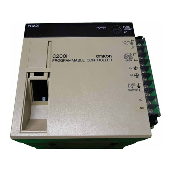
Page 40: I/O Units
I/O Units Section 2-5 C200H-PS221-C Conforms to EC directives. POWER indicator (green): Power fuse: Lights when power is 2 A, 250 V supplied to Power Supply (5.2-dia. x 20) MF51NR AC Input Voltage selector terminals Terminals Short: 100 to 120 VAC for exter- Open: 200 to 240 VAC nal con-... -
Page 41: Standard I/O Units
I/O Units Section 2-5 location on the CPU or Expansion I/O Rack. Group-2 High-density I/O Units are allocated I/O words according to I/O number set on each Unit. High-density I/O Units classified as Special I/O Unit are allocated I/O words according to the unit number set on each Unit. -
Page 42: Group-2 High-Density I/O Units
I/O Units Section 2-5 E-shape I/O Unit (10-terminal Terminal Block) I/O Unit lock notch Nameplate I/O indicators Indicate ON/ OFF status of points 10-terminal terminal block 2-5-2 Group-2 High-density I/O Units Group-2 High-density I/O Units come in two varieties; C-shape and D-shape. The shape of the two varieties is the same, but C-shape Units have only one con- nector, while the D-shape Units have two. - Page 43 I/O Units Section 2-5 Always turn the PC power off before changing a Unit’s I/O number. The new I/O number will not be recognized unless the PC has been turned off. Do not set more than one Unit to the same I/O number or set I/O numbers so that the same I/O word is allocated to more than one Unit, e.g., if you set a 64-point Unit to I/O number 0, you cannot use I/O number 1 for any Unit.
-
Page 44: High-Density I/O Units Classified As Special I/O Units
I/O Units Section 2-5 2-5-3 High-density I/O Units Classified as Special I/O Units Some High-density I/O Units are classified as Special I/O Units. Up to 10 Special I/O Units can be connected to a PC. The Units have two 24-pin connectors. In general, these Units control 32 I/O points, although some Units can control 128 I/O points when set for dynamic operation. - Page 45 I/O Units Section 2-5 4. Used when pin 1 is ON, setting the C200H-OD501/OD215 to dynamic out- put mode. I/O Unit lock notch Nameplate I/O indicators: Indicate ON/OFF status of points Unit number setting switch 24-pin connectors...
-
Page 47: Installation
SECTION 3 Installation The term “PC” can refer to a single object, but actually even the simplest PCs are usually composed of several different de- vices. In fact a PC can be physically spread throughout a building and still be called a single PC. This section describes how to install a PC System, including mounting the various Units and configuring the System. -
Page 48: Installation Environment
Installation Environment Section 3-1 Installation Environment This section details the necessary environmental conditions for installing the Caution Static electricity can damage PC components. Your body can carry an electro- static charge, especially when the humidity is low. Before touching the PC, be sure to first touch a grounded metallic object, such as a metal water pipe, in order to discharge any static build-up. -
Page 49: Mounting Units To The Backplane
Mounting Units to the Backplane Section 3-2 Noise Do not mount the PC in a control panel in which high-power equipment is installed, or near high heat-producing devices such as heaters, transformers, or large-capacity resistors. To avoid noise, make sure the point of installation is at least 200 mm away from power lines as shown in the following diagram. - Page 50 Mounting Units to the Backplane Section 3-2 The CPU of the C200HS has no I/O points built in. So, in order to complete the PC it is necessary to mount one or more I/O Units to the Backplane. Mount the I/O Unit to the Backplane by locking the top of the I/O Unit into the slot on the Backplane and rotating the I/O Unit downwards as shown in the following dia- gram.
- Page 51 Mounting Units to the Backplane Section 3-2 CPUs, I/O Power Supply Units and Slave Units must have two screws on the bottom tightened with a Phillips screwdriver. The screwdriver must be held at a slight angle, so be sure to leave enough space below each Rack. Duct 20 mm min.
- Page 52 Mounting Units to the Backplane Section 3-2 there is still some space available on the left side of the Backplane. This space is for any additional I/O Units that may be required. The figure above shows a total of eight I/O Units mounted to the Backplane. When using 16-point Output Units (models C200H-OC225/OD212/OD21A) mount them to a C200H-BCjj1-V1/V2 Backplane.
-
Page 53: Installing Racks
Installing Racks Section 3-3 Installing Racks The following figures show two side views, each consisting of a mounted CPU and two Expansion I/O Racks. Provide a space of 20 mm minimum on the upper and lower sides of each duct for ventilation and Unit replacement purposes. C200HS- C200HS-CPU21-E/CPU21-EC/ CPU01-E/CPU01-EC/... -
Page 54: I/O Connecting Cable
I/O Connecting Cable Section 3-4 The duct work shown in the following diagram is not used for mounting the Racks. Although optional, this duct work can be used to house the wires from the I/O Units that run along the sides of the Racks, keeping the wires from becoming entangled. -
Page 55: Mounting Requirements
(refer to Appendix B Specifications). If you want to mount the PC on DIN track, you can order a DIN Track from OMRON (refer to Appendix B Standard Models). DIN Tracks come in the two heights shown be- low. - Page 56 Mounting Requirements Section 3-5 DIN Track Mounting Bracket The DIN Track Mounting Bracket shown below is necessary for mounting the PC to the DIN Track. Item Specification Model DIN Track Mounting Bracket One set (two brackets) C200H-DIN01 50 cm long, 7.3 mm high PFP-50N 1 m long, 7.3 mm high PFP-100N...
-
Page 57: Installing Memory Cassettes
Installing Memory Cassettes Section 3-6 3. Loosen the screws attaching the Mounting Brackets to the Backplane. Slide the Backplane upward as shown below so that the Mounting Bracket and Backplane clamp securely onto the DIN Track. Tighten the screws. DIN Track Mounting Bracket DIN Track Hold-down bracket Slide this screw to the top of the... - Page 58 Installing Memory Cassettes Section 3-6 3. Remove the bracket from the Memory Cassette, as shown in the illustration below. Metal bracket 4. Check that the connector side goes in first and that the Cassette’s circuit components face right and then insert the Cassette into the CPU. The Cas- sette slides in along a track in the CPU.
-
Page 59: Wiring
SECTION 4 Wiring This section provides the information necessary to wire a C200HS System. Power Supply Wiring ............AC Power Supply . -
Page 60: Power Supply Wiring
AC Power Supply Section 4-2 Power Supply Wiring Pay attention to the following points when wiring the power supply. • Be sure to mount the CPU and the I/O Power Supply Unit in their proper posi- tions. • Provide power to the CPU and the I/O Power Supply Unit from the same power source. -
Page 61: Dc Power Supply
DC Power Supply Section 4-3 Tighten terminal block screws with a torque of 0.8 N-m. Use crimp terminals suitable for M3.5 screws that have the following dimension. 7 mm max. Caution Tighten power supply terminal screws with a torque of 0.8 N-m. Not tightening the screws securely may result in a fire or faulty operation. -
Page 62: Run Output Terminals
Grounding Section 4-5 RUN Output Terminals Emergency stop circuit To system RUN output control circuit Screw (3.5 mm head with self-raising pressure plate) RUN Output These terminals are short-circuited during PC operation. Use them to receive PC RUN signals, for purposes such as emergency stop circuits. Maximum switching capacity: 250 VAC, 2 A (cos = 1) -
Page 63: Backplane Insulation Plate
Backplane Insulation Plate Section 4-6 When using an Expansion I/O Rack, the Rack must also be grounded to the GR terminal. The same ground can be used for all connections. C200HS-CPU01-E/CPU01-EC/CPU03-E/CPU21-E/CPU21-EC/CPU31-E/CPU23-E/CPU33-E Screw (3.5 mm head with self-raising pressure plate) C200H-PS221/PS221-C/PS211 I/O Power Supply Unit Screw (3.5 mm head with self-rais-... -
Page 64: Standard I/O Unit Wiring
Standard I/O Unit Wiring Section 4-7 Standard I/O Unit Wiring Caution Check the I/O specifications for the I/O Units, and consider the following points. • For the I/O Units, use a DC power supply provided with reinforced insulation or double insulation if the EC directives (low-voltage directives) must be satisfied. •... - Page 65 Standard I/O Unit Wiring Section 4-7 Wire the Units so that they can be easily replaced. In addition, make sure that the I/O indicators are not affected by the wiring. Terminal Blocks Unlock the terminal block of an I/O Unit to remove the terminal block from the I/O Unit.
- Page 66 Standard I/O Unit Wiring Section 4-7 When using the NPN-current-output configuration shown below, the sensor and Input Unit should receive their power from the same supply. NPN current output Current regulator DC input Output Sensor 7 mA Power Supply NPN open-collector output Sensor Power Supply...
-
Page 67: Input Circuits
Input Circuits Section 4-8 AC Input Units Contact output AC input AC Switching AC input Prox- imity switch main circuit Input Circuits Input Leakage Current When two-wire sensors, such as photoelectric sensors, proximity sensors, or limit switches with LEDs, are used for 12/24-VDC input devices, the input bit may be turned ON erroneously by leakage current. -
Page 68: Output Circuits
Output Circuits Section 4-9 Relationship between OFF Current (I ) of the PC and Leakage Current of the Sensor (I leak leak For details, refer to sections providing precautions on leakage current. The val- will vary depending on the on the Unit. However, the value for Input ue of I Units for which OFF current specifications are not listed will be 1.3 mA. - Page 69 Output Circuits Section 4-9 Output Surge Current When connecting a transistor or triac Output Unit to an output device having a high surge current (such as an incandescent lamp), care must be taken to avoid damage to the Output Unit. The transistor and triac Output Units are capable of withstanding a surge current of ten times the rated current.
- Page 70 Output Circuits Section 4-9 Inductive Load Surge When an inductive load is connected to an I/O Unit, it is necessary to connect a Suppressor surge suppressor or diode in parallel with the load as shown below. This is so that the back EMF generated by the load will be absorbed. Diode DC input Contact Output Unit...
-
Page 71: External Wiring
System Design and Safety Considerations Section 4-11 4-10 External Wiring If power cables must be run alongside the I/O wiring (that is, in parallel with it), at least 300 mm must be left between the power cables and the I/O wiring as shown below. -
Page 72: Interlock Circuit
System Design and Safety Considerations Section 4-11 An external relay should be used to form an emergency stop circuit that turns the power to the PC OFF in the event of an emergency. An emergency stop routine in the PC program is not sufficient to ensure safety. The circuit shown below is an example of an emergency stop circuit. -
Page 73: Programmable Controller Power Interruptions
System Design and Safety Considerations Section 4-11 4-11-3 Programmable Controller Power Interruptions A sequential circuit is built into the PC to handle power interruptions. This circuit prevents malfunctions due to momentary power loss or voltage drops. A timing diagram for the operation of this circuit is shown below. The PC ignores all momentary power failures if the interruption lasts no longer than 10 ms. -
Page 75: Peripheral Devices And System Expansion
SECTION 5 Peripheral Devices and System Expansion A Programming Console or IBM PC/AT running Ladder Support Software (LSS) or SYSMAC Support Software (SSS) can be used to program and monitor the C200HS PCs. This section provides general information about the Programming Console, LSS, SSS, and ways in which the C200HS System can be expanded for more versatility. -
Page 76: Programming Console
Programming Console Section 5-1 Programming Console There are two Programming Console models that can be used with the C200HS: the C200H-PRO27-E and the CQM1-PRO01-E. The following illustration shows how a Programming Console (a C200H-PRO27-E in this case) connects to the C200HS CPU. -
Page 77: Nomenclature
Programming Console Section 5-1 5-1-1 Nomenclature The front panel of the Programming Console is shown below, taking the C200H-PRO27-E as an example. C200H-PRO27-E Programming Console LCD area Mode selector switch Instruction keys Numeric keys Operation keys Cassette jacks LCD Area This window displays the program contents and monitor status. -
Page 78: Checking Initial C200Hs Operation
Units System Manual (W143). SYSMAC LINK Systems OMRON’s SYSMAC LINK System is a communications network that connects up to 62 nodes to provide data links, data transfers, and datagram services. • Data links provide automatic transfer of up to 918 words of data in the LR and/ or DM Areas. - Page 79 (coaxial cable) SYSMAC-series PC SYSMAC NET Link Systems OMRON’s SYSMAC NET Link System is an FA-oriented limited-area network that connects up to 126 nodes to provide datagram services, data transfers, and data links. • Data transfers via datagrams are implemented using a command/response format.
- Page 80 Expanding the System Section 5-3 Note Refer to the SYSMAC NET Link System Manual (W178) for further information. SYSMAC NET Link Unit C200HS-SNT32 C200HS CPU C200HS-CPU31-E or C200HS-CPU33-E Line server Central power supply SYSMAC-series PC FA computer PC Link System A PC Link System can be used to transfer data between PCs by means of LR 0000 through LR 6315.
-
Page 81: Special I/O Units
Special I/O Units Section 5-4 Special I/O Units It is possible to connect a variety of Special I/O Units to the C200HS in the same way as the C200H. 5-4-1 Required Mounting Conditions A maximum of 10 Special I/O Units including PC Link Units can be mounted to any slot of CPU, Expansion I/O, and Slave Racks. - Page 82 Special I/O Units Section 5-4 The C200H-MD501, C200H-MD115, and C200H-MD215 can each be set for 128 dynamic input points (64 points x two circuits) and the C200H-OD501 and C200H-OD215 can each be set for 128 dynamic output points (64 points x two circuits).
- Page 83 Special I/O Units Section 5-4 Analog I/O Units The Analog Input (A/D) Units retrieve analog inputs and the Analog Output (D/A) Unit sends analog outputs. The following Analog I/O Units are available: C200H-AD001 with 4-point analog input, C200H-AD002 with 8-point analog in- put, C200H-DA001 with 2-point analog output, and C200H-DA002 with 4-point analog output The Analog Input (AD) Unit is used.
- Page 84 Special I/O Units Section 5-4 Voice Unit Voice messages can be input from dynamic microphones or cassette tape re- corders and output from loudspeakers or headsets via the Voice Unit. The Voice Unit incorporates a sentence function and word combination function, either of which can be selected to record voice messages for 64 seconds maxi- mum.
- Page 85 Special I/O Units Section 5-4 Fuzzy Logic Unit The C200H-FZ001 Fuzzy Logic Unit incorporates a high-functional fuzzy Logic processor and allows high-speed fuzzy logic. A personal computer can be connected to the Fuzzy Logic Unit via RS-232C cables for software development and monitoring. Use the C500-SU981-E Fuzzy Support Software for IBM PC/AT or compatible personal computers.
- Page 86 Special I/O Units Section 5-4 Cam Positioner Unit A single C200H-CP114 Cam Positioner Unit is as powerful as 48 mechanical cams because it can complete jobs that normally require 48 mechanical cams. It is possible to set 16-point external output and 32-point internal output as cam output.
-
Page 87: Ladder Support Software (Lss)
Data Setting Console Ladder Support Software (LSS) The LSS is a powerful support software package for the OMRON C-series Pro- grammable Controllers (PCs). The LSS runs on an IBM PC/AT or compatible personal computer, and can be use to program, monitor and control PCs. While... - Page 88 SYSMAC Support Software (SSS) Section 5-6 The SSS naturally supports all of the functionality for C-series PCs as the LSS, plus some new functions that facilitate fast, efficient programming and opera- tion.
- Page 89 SECTION 6 Troubleshooting The C200HS provides self-diagnostic functions to identify many types of abnormal system conditions. These functions mini- mize downtime and enable quick, smooth error correction. This section provides information on hardware and software errors that occur during PC operation. It also provides trouble- shooting charts for CPU Racks, Expansion I/O Racks, Input Units, and Output Units.
-
Page 90: Alarm Indicators
Reading and Clearing Errors and Messages Section 6-3 Alarm Indicators The ALM/ERR indicator on the front of the CPU provides visual indication of an abnormality in the PC. When the indicator is ON (ERROR), a fatal error (i.e., ones that will stop PC operation) has occurred; when the indicator is flashing (ALARM), a nonfatal error has occurred. -
Page 91: Error Messages
Error Messages Section 6-4 Error Messages There are basically three types of errors for which messages are displayed: in- itialization errors, non-fatal operating errors, and fatal operating errors. Most of these are also indicated by FAL number being transferred to the FAL area of the SR area. - Page 92 Error Messages Section 6-4 Error and message FAL no. Probable cause Possible correction Interrupt subroutine Check the interrupt Interrupt subroutine error containing Special I/O Unit subroutine and PC Setup. refresh was too long. SYS FAIL FAL8B Cyclic Special I/O Unit refreshing was not disabled for interrupt subroutine refresh.
- Page 93 Error Messages Section 6-4 Communications Errors The COMM or COMM 1 indicator will go out for errors in communications be- tween the peripheral port and a peripheral device and COMM 2 will will go out for errors in communications between the RS-232C port and a peripheral device. If an error is indicated, check the communications path and the C200HS program.
- Page 94 Error Messages Section 6-4 Error and message FAL no. Probable cause Possible correction Too many Units Two or more Special I/O Perform the I/O Table Read Units are set to the operation to check unit I/O UNIT OVER same unit number numbers, and eliminate duplications.
-
Page 95: Cpu Racks And Expansion I/O Racks
CPU Racks and Expansion I/O Racks Section 6-5 Other Error Messages A number of other error messages are detailed within this manual. Errors in pro- gram input and debugging and errors in cassette tape operation are detailed in the C200HS Operation Manual (W235). Information on error flags is also con- tained in the C200HS Operation Manual (W235). -
Page 96: Input Units
Input Units Section 6-6 Input Units Error Probable cause Possible correction Indicator lights are turned off, and no No external input power supply is Provide a power supply. inputs turn ON. pu s u provided. The external input voltage is low. Supply the rated voltage. -
Page 97: Output Units
Output Units Section 6-7 Output Units Error Probable cause Possible correction No outputs turn ON. A load power supply is not provided. Provide the power supply. The load power supply voltage is low. Provide the rated voltage. Terminal screws are loose. Tighten the terminal screws. -
Page 99: Inspection And Maintenance
SECTION 7 Inspection and Maintenance Certain consumable items in a PC (such as fuses, relays, and batteries) need occasional replacement. This section explains how to replace these items. Always keep spare items on hand so that they can be used as immediate replacements when need- CPU and Power Supply Fuses . -
Page 100: Cpu And Power Supply Fuses
Output Unit Fuses Section 7-2 CPU and Power Supply Fuses Turn counterclockwise to remove, clockwise to attach Standard screwdriver To replace a fuse, follow the steps below. 1, 2, 3... 1. Turn OFF the power to the PC. 2. Remove the fuse holder by turning it approximately 50° counterclockwise with a standard screwdriver. -
Page 101: Output Unit Relays
For further details, consult the fuse manufacturer. 2. Fuses in High-density I/O Units cannot be replaced by the user. Refer to your OMRON dealer for service. Output Unit Relays The following Output Units provide relay sockets that allow the Relays to be re- placed if they should go bad. - Page 102 Output Unit Relays Section 7-3 To replace a Relay, follow the steps below: 1, 2, 3... 1. Turn OFF the power to the PC. 2. Detach the terminal block by unlocking the lock levers at the top and bottom of the terminal block. 3.
- Page 103 Output Unit Relays Section 7-3 OC222 OC223 OC225 OC222V OC224V...
-
Page 104: Batteries
Batteries Section 7-4 OC226 7. A Relay puller is provided inside the rear of the case when the Unit is deliv- ered. Use the Relay puller to pull out the Relay as shown below. Insert a new Relay. Relays for the C200H-OC222V/OC224V/OC226V can be replaced without using the Relay puller. - Page 105 Batteries Section 7-4 2. Remove the cover from the battery compartment of the CPU Unit. 3. Remove the old Battery Set. 4. Install the new Battery Set as shown in the following diagram. Connector CPU01-E/03-E/01-EC Battery 5. Replace the cover of the battery compartment. 6.
-
Page 107: A Standard Models
Appendix A Standard Models C200HS Racks Name Specifications Model number Backplane (same for all Racks) 10 slots C200H-BC101-V2 8 slots C200H-BC081-V2 5 slots C200H-BC051-V2 3 slots C200H-BC031-V2 CPU Rack C200HS-CPU01-E 100 to 120/200 to 240 VAC w/built-in power supply Conforms to EC C200HS-CPU01-EC directives (see note) RS-232C port... - Page 108 Standard Models Appendix A C200H Standard I/O Units Name Specifications Model number Input Units AC Input Unit 8 pts 100 to 120 VAC C200H-IA121 16 pts 100 to 120 VAC C200H-IA122/IA122V 8 pts 200 to 240 VAC C200H-IA221 16 pts 200 to 240 VAC C200H-IA222/IA222V DC Input Unit...
- Page 109 Standard Models Appendix A Note 1. If the Interrupt Input Unit is mounted on an Expansion I/O Rack, the interrupt function cannot be used and the Interrupt Input Unit will be treated as an ordinary 8-point Input Unit. Moreover, Interrupt Input Units cannot be used on Slave Racks.
- Page 110 Standard Models Appendix A Name Specifications Model number Analog I/O Analog Input 4 to 20 mA, 1 to 5/0 to 10 V (switchable); 4 inputs C200H-AD001 Units Unit 4 to 20 mA, 1 to 5/0 to 10/–10 to 10 V (switchable); 8 inputs C200H-AD002 Analog 4 to 20 mA, 1 to 5/0 to 10 V (switchable);...
- Page 111 Standard Models Appendix A Name Specifications Model number Fuzzy Logic Unit Up to 8 inputs and 4 outputs. (I/O to and from specified data area words) C200H-FZ001 Fuzzy C500-SU981-E Available on either 3.5” or 5.25” floppy disks. Support Software Note For Read/Write Head and Data Carrier combinations, refer to the V600 FA ID System R/W Heads and EE- PROM Data Carriers Operation Manual and Supplement or V600 FA ID System R/W Heads and SRAM Data Carriers Operation Manual and Supplement.
- Page 112 Standard Models Appendix A Name Specifications Model number Bus Connection Unit Connects SYSMAC LINK Unit or SYSMAC For 1 Unit C200H-CE001 NET Li k U i NET Link Unit to C200HS-CPU31-E/CPU33-E C200HS CPU31 E/CPU33 E For 2 Units C200H-CE002 CompoBus Units Name Specifications Model number...
- Page 113 Standard Models Appendix A Link Adapters Name Specifications Model number Link Adapter 3 RS-422 connectors 3G2A9-AL001 3 optical connectors (APF/PCF) 3G2A9-AL002-PE 3 optical connectors (PCF) 3G2A9-AL002-E 1 connector each for APF/PCF, RS-422, and RS-232C 3G2A9-AL004-PE 1 connector each for PCF, RS-422, and RS-232C 3G2A9-AL004-E 1 connector each for APF/PCF and APF 3G2A9-AL005-PE...
- Page 114 Standard Models Appendix A H-PCF Name Specifications Model number Optical Fiber Cable 10 m, black Two-core cable S3200-HCCB101 SYSMAC BUS SYSMAC WAY SYSMAC BUS, SYSMAC WAY S3200-HCCB501 50 m, black 100 m, black S3200-HCCB102 500 m, black S3200-HCCB502 1000 m, black S3200-HCCB103 10 m, orange S3200-HCCO101...
- Page 115 Standard Models Appendix A Head Unit Name Specifications Model number Head Unit (a set consisting of light SYSMAC BUS: S3200-CAT2822 source unit and connector adapter) C200H-RM001-PV1 (see note) C200H-RT001/RT002-P SYSMAC NET: S3200-CAT3202 S3200-LSU03-V1/LSU03-01E C500-SNT31-V4 3G8FX-TM111 3G8SX-TM111 Note: Use a proper Head Unit model for the optical module to be used. If two types of optical modules (unit type and board type) are used, order an Optical Power Tester plus a proper Head Unit model.
- Page 116 Standard Models Appendix A Programming Devices Name Specifications Model number Programming Console Hand-held, w/backlight; requires the C200H-CN222 or C200H-PR027-E C200H-CN422, see below 2-m Connecting Cable attached. CQM1-PRO01-E Programming Console Used to attach Hand-held Programming Console to a panel. C200H-ATT01 Mounting Bracket Programming Console Con- For Hand-held Programming Console C200H-CN222...
-
Page 117: B Specifications
Appendix B Specifications The following figures and tables provide specifications for each Unit of the C200HS. I/O Units may take on one of three different shapes and are sometimes referred to as A-shape Units, B-shape Units, or E-shape Units. Group-2 High-density I/O Units take on one of two different shapes and are sometimes referred to as C-shape Units or D-shape Units. - Page 118 Specifications Appendix B are not isolated from each other. If a dielectric strength test is conducted at 50 VDC or higher, internal components such as capacitors will be damaged. If a short-circuit test must be conducted, use a device such as a tester. Acceleration (G) Amplitude 0.075 mm...
- Page 119 Specifications Appendix B CPU Specifications Control Method Stored program I/O Control Cyclic scan and immediate processing are both possible. Method Programming Ladder diagram Method Instruction Length 1 address/instruction, 1 to 4 words/instruction Number of CPU01-E/01-EC/03-E/21-E/23-E: 225 (14 basic instructions + 211 special instructions) Instructions CPU31-E/33-E: 229 (14 basic instructions + 215 special instructions) Basic instructions: 0.375 to 1.313 µs...
- Page 120 Specifications Appendix B Standard I/O Units AC Input Unit C200H-IA121 Rated Input Voltage 100 to 120 VAC 50/60 Hz Operating Input Voltage 85 to 132 VAC 50/60 Hz Input Impedance 9.7 kW (50 Hz), 8 kW (60 Hz) Input Current 10 mA typical (at 100 VAC) ON Voltage 60 VAC min.
- Page 121 Specifications Appendix B AC Input Unit C200H-IA122/IA122V Rated Input Voltage 100 to 120 VAC 50/60 Hz Operating Input Voltage 85 to 132 VAC 50/60 Hz Input Impedance 9.7 kW (50 Hz), 8 kW (60 Hz) Input Current 10 mA typical (at 100 VAC) ON Voltage 60 VAC min.
- Page 122 Specifications Appendix B AC Input Unit C200H-IA221 Rated Input Voltage 200 to 240 VAC 50/60 Hz Operating Input Voltage 170 to 264 VAC 50/60 Hz Input Impedance 21 kW (50 Hz), 18 kW (60 Hz) Input Current 10 mA typical (at 200 VAC) ON Voltage 120 VAC min.
- Page 123 Specifications Appendix B AC Input Unit C200H-IA222/IA222V Rated Input Voltage 200 to 240 VAC 50/60 Hz Operating Input Voltage 170 to 264 VAC 50/60 Hz Input Impedance 21 kW (50 Hz), 18 kW (60 Hz) Input Current 10 mA typical (at 200 VAC) ON Voltage 120 VAC min.
- Page 124 Specifications Appendix B No-Voltage Contact Input Unit C200H-ID001 Input Voltage No-voltage contact/NPN output type (negative common) Input Impedance 3 kW Input Current 7 mA typical ON Voltage (14.4 VDC min.) OFF Voltage (5.0 VDC max.) ON Response Time 1.5 ms max. (no-voltage contact, at 25°C) OFF Response Time 1.5 ms max.
- Page 125 Specifications Appendix B No-Voltage Contact Input Unit C200H-ID002 Input Voltage No-voltage contact/PNP output type (positive common) Input Impedance 3 kW Input Current 7 mA typical ON Voltage (14.4 VDC min.) OFF Voltage (5.0 VDC max.) ON Response Time 1.5 ms max. (no-voltage contact, at 25°C) OFF Response Time 1.5 ms max.
- Page 126 Specifications Appendix B DC Input Unit C200H-ID211 Rated Input Voltage 12 to 24 VDC Operating Input Voltage 10.2 to 26.4 VDC Input Impedance 2 kW Input Current 10 mA (at 24 VDC) ON Voltage 10.2 VDC min. OFF Voltage 3.0 VDC max. ON Response Time 1.5 ms max.
- Page 127 Specifications Appendix B DC Input Unit C200H-ID212 Rated Input Voltage 24 VDC Operating Input Voltage 20.4 to 26.4 VDC Input Impedance 3 kW Input Current 7 mA (at 24 VDC) ON Voltage 14.4 VDC min. OFF Voltage 5.0 VDC max. ON Response Time 1.5 ms max.
- Page 128 Specifications Appendix B AC/DC Input Unit C200H-IM211 Rated Input Voltage 12 to 24 VDC Operating Input Voltage 10.2 to 26.4 VDC Input Impedance 2 kW Input Current 10 mA typical (at 24 VDC) ON Voltage 10.2 VDC min. OFF Voltage 3.0 VDC max.
- Page 129 Specifications Appendix B AC/DC Input Unit C200H-IM212 Rated Input Voltage 24 VDC Operating Input Voltage 20.4 to 26.4 VDC Input Impedance 3 kW Input Current 7 mA typical (at 24 VDC) ON Voltage 14.4 VDC min. OFF Voltage 5.0 VDC max. ON Response Time 15 ms max.
- Page 130 Specifications Appendix B Triac Output Unit C200H-OA121-E Max. switching capacity 1 A 120 VAC, 50/60 Hz (4 A/Unit) Min. switching capacity 10 mA (resistive load)/40 mA (inductive load) 10 VAC Leakage Current 3 mA (100 VAC) max. Residual Voltage 1.2 V max. ON Response Time 1 ms max.
- Page 131 Specifications Appendix B Triac Output Unit C200H-OA122-E Max. Switching Capacity 1.2 A 120 VAC, 50/60 Hz (4 A/Unit) Max. Inrush Current 15 A (pulse width: 100 ms) 30 A (pulse width: 10 ms) Min. Switching Capacity 100 mA 10 VAC/50 mA 24 VAC/10 mA 100 VAC min.
- Page 132 Specifications Appendix B Triac Output Unit C200H-OA222V Max. Switching Capacity 0.3 A 250 VAC, 50/60 Hz (2 A/Unit) Min. Switching Capacity 10 mA (resistive load)/40 mA (inductive load) 10 VAC Leakage Current 3 mA (100 VAC) max./6 mA (200 VAC) max. Residual Voltage 1.2 V max.
- Page 133 Specifications Appendix B Triac Output Unit C200H-OA223 Max. Switching Capacity 1.2 A 250 VAC, 50/60 Hz (4 A/Unit) Max. Inrush Current 15 A (pulse width: 100 ms) 30 A (pulse width: 10 ms) Min. Switching Capacity 100 mA 10 VAC/50 mA 24 VAC/10 mA 100 VAC min.
- Page 134 Specifications Appendix B Triac Output Unit C200H-OA224 Max. Switching Capacity 0.5 A 250 VAC, 50/60 Hz (2 A/Unit) Max. Inrush current 10 A (pulse width: 100ms) 20 A (pulse width: 10 ms) Min. Switching Capacity 100 mA 10 VAC/50 mA 24 VAC/10 mA 100 VAC min.
- Page 135 Specifications Appendix B Contact Output Unit C200H-OC221 Max. Switching Capacity 2 A 250 VAC (cosf = 1), 2 A 250 VAC (cosf = 0.4), 2 A 24 VDC (8 A/Unit) Min. Switching Capacity 10 mA 5 VDC Relay G6B-1174P-FD-US (24 VDC) w/socket Service Life of Relay Electrical: 500,000 operations (resistive load)/ 100,000 operations (inductive load)
- Page 136 Specifications Appendix B Contact Output Unit C200H-OC222 Max. Switching Capacity 2 A 250 VAC (cosf = 1), 2 A 250 VAC (cosf = 0.4), 2 A 24 VDC (8 A/Unit) Min. Switching Capacity 10 mA 5 VDC Relay G6B-1174P-FD-US (24 VDC) w/socket Service Life of Relay Electrical: 500,000 operations (resistive load)/ 100,000 operations (inductive load)
- Page 137 Specifications Appendix B Contact Output Unit C200H-OC223 Max. Switching Capacity 2 A 250 VAC (cosf = 1), 2 A 250 VAC (cosf = 0.4), 2 A 24 VDC (10 A/Unit) Min. Switching Capacity 10 mA 5 VDC Relay G6B-1174-P-FD-US (24 VDC) w/socket Service Life of Relay Electrical: 500,000 operations (resistive load)/ 100,000 operations (inductive load)
- Page 138 Specifications Appendix B Contact Output Unit C200H-OC224 Max. Switching Capacity 2 A 250 VAC (cosf = 1), 2 A 250 VAC (cosf = 0.4), 2 A 24 VDC (16 A/Unit) Min. Switching Capacity 10 mA 5 VDC Relay G6B-1174-P-FD-US (24 VDC) w/socket Service Life of Relay Electrical: 500,000 operations (resistive load)/ 100,000 operations (inductive load)
- Page 139 Specifications Appendix B Contact Output Unit C200H-OC225 Max. Switching Capacity 2 A 250 VAC (cosf = 1), 2 A 250 VAC (cosf = 0.4), 2 A 24 VDC (8 A/Unit) Min. Switching Capacity 10 mA 5 VDC Relay G6B-1174P-FD-US (24 VDC) w/socket Service Life of Relay Electrical: 500,000 operations (resistive load)/ 100,000 operations (inductive load)
- Page 140 Specifications Appendix B Contact Output Unit C200H-OC222V Max. Switching Capacity 2 A 250 VAC (cosf = 1), 2 A 250 VAC (cosf = 0.4), 2 A 24 VDC (8 A/Unit) Min. Switching Capacity 10 mA 5 VDC Relay G6R-1 (24 VDC) w/socket Service Life of Relay Electrical: 300,000 operations Mechanical: 10,000,000 operations...
- Page 141 Specifications Appendix B Contact Output Unit C200H-OC226 Max. Switching Capacity 2 A 250 VAC (cosf = 1), 2 A 250 VAC (cosf = 0.4), 2 A 24 VDC (8 A/Unit) Min. Switching Capacity 10 mA 5 VDC Relay G6R-1 (24 VDC) w/socket Service Life of Relay Electrical: 300,000 operations Mechanical: 10,000,000 operations...
- Page 142 Specifications Appendix B Contact Output Unit C200H-OC224V Max. Switching Capacity 2 A 250 VAC (cosf = 1), 2 A 250 VAC (cosf = 0.4), 2 A 24 VDC (16 A/Unit) Min. Switching Capacity 10 mA 5 VDC Relay G6R-1 (24 VDC) w/socket Service Life of Relay Electrical: 300,000 operations Mechanical: 10,000,000 operations...
- Page 143 Appendix B Life Expectancy of Contact Output Unit The C200H-OC221/222/223/224/225 Contact Output Unit uses OMRON’s G6B-1174P-FD-US Relay. The life of the G6B-1174P-FD-US Relay varies with the contact current and ambient temperature. Refer to the following graphs to calculate this value.
- Page 144 Specifications Appendix B Arc killer circuit examples are listed in the following table. Circuit Current Characteristic Required element CR method If the load is a relay or solenoid, there The capacitance of the capacitor must be 1 to 0.5 µF per contact current of 1 is a time lag between the moment the circuit is opened and the moment the A and resistance of the resistor must...
- Page 145 Specifications Appendix B Transistor Output Unit C200H-OD211 +10% Max. Switching Capacity 0.3 A 24 VDC (2 A/Unit) –15% Min. Switching Capacity None Leakage Current 0.1 mA max. Residual Voltage 1.4 V max. ON Response Time 0.2 ms max. OFF Response Time 0.3 ms max.
- Page 146 Specifications Appendix B Transistor Output Unit C200H-OD212 +10% Max. Switching Capacity 0.3 A 24 VDC (4.8 A/Unit) –15% Min. Switching Capacity None Leakage Current 0.1 mA max. Residual Voltage 1.4 V max. ON Response Time 0.2 ms max. OFF Response Time 0.3 ms max.
- Page 147 Specifications Appendix B Transistor Output Unit C200H-OD213 +10% Max. Switching Capacity 2.1 A 24 VDC (5.2 A/Unit) NPN output –15% Min. Switching Capacity None Leakage Current 0.1 mA max. Residual Voltage 1.4 V max. ON Response Time 0.2 ms max. OFF Response Time 0.3 ms max.
- Page 148 Specifications Appendix B Transistor Output Unit C200H-OD214 (Load Short-circuit Protection Provided) +10% Max. Switching Capacity 24 VDC 0.8 A (2.4 A/Unit) surge current –15% 2 A (source type) PNP output Min. Switching Capacity None Leakage Current 1 mA max. Residual Voltage 1.5 V max.
- Page 149 Specifications Appendix B C200H-OD214 Short-Circuit Protection The C200H-OD214 Output Unit is equipped with two types of short-circuit protection: overcurrent protection and thermal protection. Any short-circuit must be eliminated immediately in order to avoid damage to the Unit. Overcurrent Protection When the output current reaches 2 A, the alarm output turns ON, and the alarm indicator lights. Make sure the surge current of the load does not exceed 2 A, or the alarm may be activated.
- Page 150 Specifications Appendix B Transistor Output Unit C200H-OD216 Max. Switching Capacity 0.3 A 5 to 24 VDC Min. Switching Capacity 10 mA 5 VDC Leakage Current 0.1 mA max. Residual Voltage 1.5 V max. ON Response Time 1.5 ms max. OFF Response Time 2 ms max.
- Page 151 Specifications Appendix B Transistor Output Unit C200H-OD217 Max. Switching Capacity 0.3 A 5 to 24 VDC Min. Switching Capacity 10 mA 5 VDC Leakage Current 0.1 mA max. Residual Voltage 1.5 V max. ON Response Time 1.5 ms max. OFF Response Time 2 ms max.
- Page 152 Specifications Appendix B Transistor Output Unit C200H-OD411 Max. Switching Capacity 12 to 48 VDC 1 A (3 A/Unit) Min. Switching Capacity None Leakage Current 0.1 mA max. Residual Voltage 1.4 V max. ON Response Time 0.2 ms max. OFF Response Time 0.3 ms max.
- Page 153 Specifications Appendix B Transistor Output Unit C200H-OD21A (Load Circuit Protection Provided) +10% Max. Switching Capacity 24 VDC , 1.0 A (4 A/Unit) surge current –15% 1.6 A (sourcing type) PNP output Min. Switching Capacity None Leakage Current 0.1 mA max. Residual Voltage 0.8 V max.
- Page 154 Specifications Appendix B Terminal Connections +24 VDC 24 VDC C200HS-INT01 Interrupt Input Unit The Interrupt Input Unit temporarily interrupts the main program by means of in- puts, and executes interrupt subroutines. It must be mounted to a C200HS CPU Rack, and there can be only one Interrupt Input Unit on the Rack. (It is possible to mount it to an Expansion I/O Rack, but in that case it will be treated as a Standard Input Unit and will have no interrupt functions.) Use a C200H-BCjj1-V2 Back- plane.
- Page 155 Specifications Appendix B Circuit Configuration 2 kW Internal 0.01 Circuit 12 to 24 VDC Input indicator Either plus or minus can be used for the input power supply. Terminal Connections 12 to 24 VDC Group-2 High-density I/O Units In the following diagrams, “m” is the first word allocated to the Unit in PC memory. DC Input Unit C200H-ID111 (64 Points) +10% Rated Input Voltage...
- Page 156 Specifications Appendix B Circuit Configuration 1000 pF Internal IN00 Circuit 820 W IN07 IN08 2.7 kW IN15 Indicator IN00 switch circuit IN07 IN08 Input indicator IN15 IN00 1000 pF Internal Circuit IN07 820 W IN08 2.7 kW IN15 IN00 IN07 IN08 IN15 Terminal Connections...
- Page 157 Specifications Appendix B 2. The power can be supplied in either polarity, but the same polarity must be used for all COM terminals in each connector. Connect power supply wiring to every COM terminal, even though the COM terminals in each connector are connected internally.
- Page 158 Specifications Appendix B Terminal Connections I/O word “m” I/O word “m+1” 24 VDC 24 VDC 24 VDC 24 VDC Note 1. I/O word “m” is determined by the I/O number setting (m = IR 030 + 2 × I/O number). 2.
- Page 159 Specifications Appendix B Circuit Configuration and Simultaneously Usable Points 1000 pF Internal IN00 Circuit Input Voltage: 680 W 24.0 VDC IN07 IN08 5.6 kW Input Voltage: 26.4 VDC IN15 Indicator IN00 switch circuit IN07 IN08 Input indicator IN15 IN00 1000 pF Internal Circuit IN07...
- Page 160 Specifications Appendix B 2. The power can be supplied in either polarity, but the same polarity must be used for all COM terminals in each connector. Connect power supply wiring to every COM terminal, even though the COM terminals in each connector are connected internally.
- Page 161 Specifications Appendix B Terminal Connections m words m + 1 words (m = 030 + 2 × I/O number) 24 VDC 24 VDC 24 VDC 24 VDC Note 1. The polarity of the input power supply can be either positive or negative. The polarity of all commons, however, must be the same.
- Page 162 Specifications Appendix B Circuit Configuration 0.01 µF Input LED indicator Ambient Temperature for Simultaneously ON Points 470 Ω Input voltage: 20.4 VDC 3.9 kΩ Input voltage: 24.0 VDC Input voltage: 26.4 VDC Input LED indicator 0.01 µF 470 Ω 3.9 kΩ Ambient temperature Terminal Connections (m = 030 + 2 ×...
- Page 163 Specifications Appendix B Transistor Output Unit C200H-OD218 (32 Points) Max. Switching Capacity 16 mA 4.5 VDC to 100 mA 26.4 VDC (see below) Min. Switching Capacity None Leakage Current 0.1 mA max. Residual Voltage 0.8 V max. ON Response Time 0.1 ms max.
- Page 164 Specifications Appendix B Terminal Connections I/O word “m” I/O word “m+1” 4.5 to 26.4 VDC Note 1. I/O word “m” is determined by the I/O number setting (m = IR 030 + 2 × I/O number). 2. When the fuse blows, the F indicator lights and the error flag in AR 02 corresponding to the I/O number is turned ON.
- Page 165 Specifications Appendix B Circuit Configuration 4.5 to 26.4 VDC OUT00 OUT07 Internal Circuit Fuse 4.5 to 26.4 VDC OUT08 OUT15 Indicator switch/ Output indicator fuse blowout F indicator detection circuit 4.5 to 26.4 VDC OUT00 OUT07 Internal Circuit Fuse 4.5 to 26.4 VDC OUT08 OUT15...
- Page 166 Specifications Appendix B Terminal Connections I/O word “m+1” I/O word “m” I/O word “m+2” I/O word “m+3” 4.5 to 26.4 VDC Note 1. I/O word “m” is determined by the I/O number setting (m = IR 030 + 2 × I/O number). 2.
- Page 167 Specifications Appendix B Note When the short-circuit/overload protection is activated for a contact point, the output for that point is turned OFF. At the same time, lamp “F” lights up, and the alarm from AR0205 to AR0214 corresponding to the I/O number turns ON.
- Page 168 Specifications Appendix B High-density I/O Units (Special I/O Units) TTL Input Unit C200H-ID501 (32 Points) Rated Input Voltage 5 VDC Operating Input Voltage 4.5 to 5.5 VDC Input Impedance 1.1 kW Input Current 3.5 mA (at 5 VDC) ON Voltage 3.0 VDC min.
- Page 169 Specifications Appendix B Terminal Connections I/O word “n” I/O word “n+1” COM1 COM0 5 VDC 5 VDC 5 VDC 5 VDC COM2 COM3 Note 1. I/O word “n” is determined by the unit number setting (n = IR 100 + 10 × unit number). 2.
- Page 170 Specifications Appendix B Circuit Configuration COM0 1000 pF IN00 620 W IN07 COM1 IN08 5.6 kW IN15 Internal Circuit COM2 1000 pF IN00 620 W IN07 COM3 IN08 5.6 kW IN15 Terminal Connections I/O word “n” I/O word “n+1” COM1 COM0 24 VDC 24 VDC...
- Page 171 Specifications Appendix B TTL Output Unit C200H-OD501 (Used as a 32-point Output Unit) Max. Switching Capacity 5 VDC 35 mA (280 mA/common, 1.12 A/Unit; output resistance 4.7 kW) Min. Switching Capacity None Leakage Current 0.1 mA max. Residual Voltage 0.4 V max. ON Response Time 0.2 ms max.
- Page 172 Specifications Appendix B Terminal Connections I/O word “n” I/O word “n+1” +5 VDC +5 VDC 5 VDC 5 VDC COM1 COM0 5 VDC 5 VDC COM2 COM3 +5 VDC +5 VDC Note 1. I/O word “n” is determined by the unit number setting (n = IR 100 + 10 × unit number). 2.
- Page 173 Specifications Appendix B Circuit Configuration 5 VDC 4.7 kW DATA00 DATA07 COM0 Fuse 5 VDC 4.7 kW Internal STB00 Circuit STB07 COM1 Fuse 5 VDC DATA08 DATA15 COM2 5 VDC STB08 STB15 COM3 Terminal Connections 5 VDC COM1 COM0 DATA8 STB8 STB7 DATA7...
- Page 174 Specifications Appendix B 5. Each output terminal has an output resistance of 4.7 kW. Transistor Output Unit C200H-OD215 (Used as 32-point Output Unit) Max. Switching Capacity 16 mA 4.5 VDC to 100 mA 26.4 VDC (see page 172) 800 mA/common, 3.2 A/Unit Min.
- Page 175 Specifications Appendix B Terminal Connections I/O word “n” I/O word “n+1” +5 to 24 VDC +5 to 24 VDC 5 to 24 5 to 24 COM1 COM0 5 to 24 5 to 24 COM2 COM3 +5 to 24 VDC +5 to 24 VDC Note 1.
- Page 176 Specifications Appendix B Circuit Configuration 4.5 to 26.4 VDC DATA00 DATA07 COM0 Fuse 4.5 to 26.4 VDC STB00 Internal Circuit STB07 COM1 Fuse 4.5 to 26.4 VDC DATA08 DATA15 COM2 4.5 to 26.4 VDC STB08 STB15 COM3 Terminal Connections 5 to 24 VDC COM1 COM0 DATA8...
- Page 177 Specifications Appendix B 4. The strobe signal has negative logic regardless of the setting of pin 5. 5. When the output device (such as a numeric display) does not have a pull-up resistor, it is necessary to add a pull-up resistor between the + terminal of the power supply and each data (0 to 15) and strobe (0 to 15) terminal.
- Page 178 Specifications Appendix B Terminal Connections I/O word “n” I/O word “n+1” +5 VDC +5 VDC COM1 COM0 5 VDC 5 VDC 5 VDC 5 VDC COM2 COM3 Note 1. I/O word “n” is determined by the unit number setting (n = IR 100 + 10 × unit number). 2.
- Page 179 Specifications Appendix B Circuit Configuration 5 VDC 4.7 kW STB00 STB07 COM0 Fuse 5 VDC Internal STB08 Circuit STB15 1.1 kW COM1 DATA00 DATA07 2.4 kW COM2 DATA08 DATA15 COM3 Terminal Connections DATA0 DATA8 DATA1 DATA9 5 VDC 5 VDC DATA2 DATA10 DATA3...
- Page 180 Specifications Appendix B 12 VDC Input/Transistor Output Unit C200H-MD115 (Used as I/O Unit with 16 Inputs and 16 Outputs) Output Specifications Max. Switching Capacity 16 mA 4.5 VDC to 100 mA 26.4 VDC (see page (Connector 1) 172), 800 mA/common, 1.6 A/Unit Min.
- Page 181 Specifications Appendix B Terminal Connections I/O word “n” I/O word “n+1” +5 to 24 VDC +5 to 24 VDC COM1 COM0 12 VDC 12 VDC 5 to 24 5 to 24 COM2 COM3 Note 1. I/O word “n” is determined by the unit number setting (n = IR 100 + 10 × unit number). 2.
- Page 182 Specifications Appendix B Circuit Configuration 12 VDC STB00 STB07 COM0 Fuse 12 VDC Internal STB08 Circuit STB15 2.7 kW COM1 DATA00 DATA07 620 W 1000 pF COM2 DATA08 DATA15 COM3 Terminal Connections DATA0 DATA8 DATA1 DATA9 12 VDC 12 VDC DATA2 DATA10 DATA3...
- Page 183 Specifications Appendix B 24 VDC Input/Transistor Output Unit C200H-MD215 (Used as I/O Unit with 16 Inputs and 16 Outputs) Output Specifications Max. Switching Capacity 16 mA 4.5 VDC to 100 mA 26.4 VDC (see page (Connector 1) 172), 800 mA/common, 1.6 A/Unit Min.
- Page 184 Specifications Appendix B Terminal Connections I/O word “n” I/O word “n+1” +5 to 24 VDC +5 to 24 VDC COM1 COM0 24 VDC 24 VDC 5 to 24 5 to 24 COM2 COM3 Note 1. I/O word “n” is determined by the unit number setting (n = IR 100 + 10 × unit number). 2.
- Page 185 Specifications Appendix B Circuit Configuration 24 VDC STB00 STB07 COM0 Fuse 12 VDC Internal STB08 Circuit STB15 COM1 DATA00 DATA07 COM2 DATA08 DATA15 COM3 Terminal Connections DATA0 DATA8 DATA1 DATA9 12 VDC 12 VDC DATA2 DATA10 DATA3 DATA11 COM1 COM0 Keyboard, STB15 STB7...
- Page 186 Specifications Appendix B High-density I/O Unit Limitations Limitations on the switching capacity of C200H-OD215/MD115/MD215 Transistor Output Units and the usable number of I/O points in the C200H-ID215 and C200H-MD215 are shown below. Switching Capacity The switching capacity of C200H-OD215/MD115/MD215 Transistor Output Units depends on the power supply voltage, as shown below.
- Page 187 Specifications Appendix B Usable I/O Points (C200H-MD215) To prevent overheating in the C200H-MD215 and prevent early failure of internal components, limit the number of input points ON simultaneously. The number of points that can be on simultaneously depends on both the temper- ature and the input voltage.
- Page 188 Specifications Appendix B Pin 3: Minimum Pulse Width Setting of Pulse Input Response Use pin 3 only when pin 2 of the C200H-ID501, C200H-ID215, C200H-MD501, C200H-MD115, and C200H- MD215 is set to ON (i.e., when pulse input is set). Pin 3 Minimum response input pulse width 1 ms 4 ms...
- Page 189 Specifications Appendix B Analog Timer Unit C200H-TM001 Item Specifications Oscillation Method CR oscillation Time Setting Range Use the DIP switch to set any of the following four ranges, according to the chart shown on the next page. 0.1 to 1 second (typical) 1 to 10 seconds (typical) 10 to 60 seconds (typical) 1 to 10 minutes (typical)
- Page 190 Specifications Appendix B Internal variable resistors TM001 Indicators These variable re- The SET indicators in the top row light when the cor- sistors are used to responding timer is operating. The TIME UP indica- set the timers. The tors in the bottom row light when the corresponding settings of these re- timer (T0 through T3) turns ON.
- Page 191 Specifications Appendix B External variable resistor connector External variable resistor Caution Ensure that the external variable resistor connectors are open when using the internal variable resistor. Standard B7A Interface Unit C200H-B7AI1/B7AO1 The Standard B7A Interface Unit used with the B7A Link Terminal allows the transmission and reception of 16-point I/O data over two wires.
- Page 192 Specifications Appendix B I/O Indicator Indicates the ON or OFF status of input from the B7A Link Terminal or the ON and OFF status of output to the B7A Link Terminal. ERR Indicator Incorporated by the B7AI1 and lit when the B7AI1’s data transmission or reception is abnormal. Connection Terminals SIG: Connects to the SIG terminal of the B7A Link Terminal.
- Page 193 Specifications Appendix B Group-2 B7A Interface Units (C200H-B7Ajj) A Group-2 B7A Interface Unit used with two or four B7A Link Terminals allows the transmission and reception of 32-point or 64-point I/O data over two-conductor cables. Group-2 B7A Interface Unit C200HS Input B7A Link Terminal Sensor Switch...
- Page 194 Specifications Appendix B Connectable B7A Link Terminals Only 16-point B7A Link Terminals can be connected to a B7A Interface Unit. Input Terminals Type Model Transmission delay Screw terminals Standard (19.2 ms) B7A-T6j1 B7AS-T6j1 B7A-T6j6 High-speed (3 ms) B7AS-T6j6 Modular B7A-T6D2 Standard (19.2 ms) B7A-T6D7 High-speed (3 ms)
- Page 195 Specifications Appendix B Parts and Names (C200H-B7A22 shown below) Front I/O number switch This switch determines the words allocated to the Unit. Status indicators The indicators depend on the model of B7A Inter- face Unit. Connection terminals Connect to the SIG terminal of the B7A Link Terminal and to the negative power terminal of the B7A Link Terminal.
- Page 196 Specifications Appendix B Indicator Operation The indicators depend on the model of B7A Interface Unit, as shown below. Name Color Function ERROR 1 Input Lights when an error occurs in transmissions from an Input B7A Link Terminal. ERROR 2 transmission For the B7A12/22, ERROR 1 is for the first word allocated to the B7A Interface ERROR error...
- Page 197 Specifications Appendix B DIP Switch Settings Set the DIP switch as described before for the various models of B7A Interface Units. C200H-B7A22/12 Function Transmission delay Standard (19.2 ms) High-speed (3 ms) Transmission error process Hold status Reset Inputs Factory setting Input mode 16 inputs 15 inputs + error input...
- Page 198 Specifications Appendix B Transmission Error Precautions Startup The Transmission Error Flag for the B7A Interface Unit will be OFF when power is turned on to the C200HS. If normal transmissions with the B7A Link Terminal are not possible within about 10 ms, the Transmission Error Flag (bit 15) will turn ON (i.e., if its operation is enabled by the input mode setting).
- Page 199 Specifications Appendix B Wiring Terminal Names and Allocations The use of the terminals depends on the model of the B7A Interface Unit. “m” indicates the first word allocated to the Unit according to the I/O number setting and can be calculated as follows: m = 030 + (2 x I/O number) C200H-B7A22 Terminal...
- Page 200 Specifications Appendix B C200H-B7A02 Terminal Name Function Word SIG OUT1 Connect to SIG terminal on Output B7A Link Terminal. – OUT1 Connect to – power supply terminal on Output B7A Link Terminal. B2, B3 Not used. m + 1 SIG OUT2 Connect to SIG terminal on Output B7A Link Terminal.
- Page 201 Specifications Appendix B Separate Power Supplies B7A Link Terminal B7A Interface Unit 12 to 24 VDC Transmission distance: 500 m max. B7A Link Terminal 12 to 24 VDC Transmission cable: VCTF 0.75 mm or higher 12 to 24 VDC High-speed Transmission Delays (3 ms): Shielded Cable Common Power Supply B7A Link Terminal B7A Interface Unit...
- Page 202 Specifications Appendix B Specifications Item C200H-B7A12 C200H-B7A02 C200H-B7A21 C200H-B7A22 I/O points 32 input points or 32 output points 16 output points and 32 output points and 30 input points and 2 16 input points or 32 input points or error inputs 15 input points + 1 30 input points + 2 error input...
- Page 203 Specifications Appendix B Note The figures shown in the “maximum current supplied” and “maximum power supplied” columns are com- puted with the power consumed by the Backplanes, CPU, Memory Cassettes, Peripheral Devices, I/O Power Supply Units, and Slave Units already calculated. Design the system so that the following conditions are satisfied.
- Page 204 Specifications Appendix B Total = 22.5 W (≤ 28 W) Example 3: Units Mounted to C200HS-CPU01-E CPU Rack OC221 Contact Output Units: 4 Units ID217 High-density Input Unit: 1 Unit OD219 High-density Output Unit: 1 Unit CT002 High-speed Counter Unit: 1 Unit External power supply used (for ID217): 0.3 A Power Supply...
- Page 205 Specifications Appendix B Unit Model number Current consumption Transistor Output C200H-OD411 0.14 A C200H-OD211 0.16 A C200H-OD212 0.18 A C200H-OD213 0.14 A C200H-OD214 C200H-OD216 0.01 A each C200H-OD217 C200H-OD21A 0.16 A Triac Output C200H-OA121-E 0.14 A C200H-OA122-E 0.18 A C200H-OA221 0.14 A C200H-OA223 0.18 A...
- Page 206 Specifications Appendix B Unit Model number Current consumption Analog Output C200H-DA001 0.65 A C200H-DA002 0.60 A Temperature Control C200H-TC001 0.33 A C200H-TC002 C200H-TC003 C200H-TC101 C200H-TC102 C200H-TC103 Heat/Cool Temperature C200H-TV001 0.33 A Control C200H-TV002 C200H-TV003 C200H-TV101 C200H-TV102 C200H-TV103 PID Control C200H-PID01 0.33 A C200H-PID02 C200H-PID03...
- Page 207 Specifications Appendix B Current Drawn from 26-V Unit Model number Current Supply consumption Contact Output C200H-OC221/OC222/OC223/ 0.075 A/8 points that OC224/OC225 turn ON simultaneously C200H-OC222V/OC224V/ 0.09 A/8 points that OC226 turn ON simultaneously Transistor Output C200H-OD216/OD217 0.075 A/8 points that turn ON simultaneously ID Sensor...
- Page 208 Specifications Appendix B C200H-PS221/PS221-C/PS211 I/O Power Supply Unit Backplane Model Width (W) Weight C200H-BC031-V2 260 mm 0.8 kg max. C200H-BC051-V2 330 mm 1.0 kg max. C200H-BC081-V2 435 mm 1.3 kg max. C200H-BC101-V2 505 mm 1.5 kg max. I/O Connecting Cables The dimensions shown below are for I/O Connecting Cables.
- Page 209 Specifications Appendix B C200H-PRO27 Programming Console The dimensions shown below are for the Programming Console. (30) C200H-CN222/CN422, C200HS-CN222/CN422 Connecting Cable 2000 (4000) Standard I/O Units The dimensions shown below are for the three shapes of Standard I/O Units mentioned throughout these specifi- cations.
- Page 210 Specifications Appendix B 19-terminal Terminal Block (B-shape I/O Units) 10-terminal Terminal Block (E-shape I/O Units) 19-terminal Terminal Block (Extended B-shape I/O Units)
- Page 211 Specifications Appendix B Terminal Dimensions M3.5 Group-2 High-density I/O Units The dimensions shown below are for the Group-2 High-density I/O Units. Group-2 High-density I/O Units (C and D Types) Dimensions with Unit Mounted Approx. 143 High-density I/O Units (Special I/O Units) The dimensions shown below are for the High-density I/O Units classified as Special I/O Units.
- Page 212 Specifications Appendix B Dimensions with Unit Mounted Fujitsu’s Connector is Used G79-jC Connecting Cable is Used G79-jC Connecting Connecting Cable cable Approx. 163 Interrupt Input Unit The dimensions shown below are for the Interrupt Input Unit classified as Special I/O Units. Standard B7A Interface Unit The dimensions shown below are for the B7A Interface Unit classified as Special I/O Units.
- Page 213 Specifications Appendix B Group-2 B7A Interface Units The dimensions shown below are for the Group-2 B7A Interface Units. Analog Timer Unit The dimensions shown below are for the Analog Timer Unit classified as Special I/O Units.
- Page 214 Specifications Appendix B Mounting Dimensions A±0.2 Four (five), M4 B ± 0.2 Backplane 118±0.2 68 to 108 80 to 120 118±0.2 Backplane Four (five), M4 Model A±0.2 B±0.2 C200H-BC031-V2 246 mm 260 mm C200H-BC051-V2 316 mm 330 mm C200H-BC081-V2 421 mm 435 mm C200H-BC101-V2 491 mm...
- Page 215 Specifications Appendix B The following is the standard panel cut dimensions for the Programming Console (conforming to DIN 43700). +1.1 +0.8 Use the C200H-ATT01 Mounting Bracket (sold separately) to mount the C200H-PRO27 Programming Console to panels. 75.5 14.1 Take the space required for the cable into consideration when mounting the Programming Console to panels. Approximately 80 mm is required.
- Page 216 Specifications Appendix B RS-232C Port Specifications RS-232C Specifications The specifications for the RS-232C port are given below. Devices that meet these specifications can be connected. Connector Pin Assignments Pin assignments for the RS-232C port are given in the following table. Abbreviation Name Direction...
- Page 217 Specifications Appendix B Applicable Connectors The following connectors are applicable. One plug and one hood are included with the CPU. CPU Unit Connector Item Model Specifications Used together (One Plug XM2A-0901 9-pin male of each provided id d Hood XM2S-0911-E 9-pin, millimeter with CPU Unit.) screws,...
-
Page 219: Glossary
Glossary ASCII code [A(merican) S(tandard) C(ode for) I(nformation) I(nterchange)] A standard com- puter code used to facilitate the interchange of information among various types of data-processing equipment. ASCII Unit An Intelligent I/O Unit. The ASCII Unit has its own CPU and 16 kilobytes of memory. - Page 220 Glossary debugging The process of checking for errors in a program. default condition The original condition of a function or system. For example, the Ladder Support Software’s (LSS) installation utility will place the LSS in the C:\LSS directory, but this default condition can be changed so that it places the LSS in a different directory.
- Page 221 Glossary or connector pins on a Unit; in terms of programming, an I/O point corresponds to an I/O bit in the IR area. I/O table Diagram written to the IR memory area listing the type of I/O units controlled by a PC.
- Page 222 PCs. Unit In OMRON PC terminology, the word Unit is capitalized to indicate any product sold for a PC System. though most of the names of these products end with the word Unit, not all do, e.g., a Remote Terminal is referred to in a collective sense as a Unit.
-
Page 223: Index
Index cycle, 6 cycle time, 6 ambient temperature, 34 Analog Timer Unit D–E dimensions, 199 specifications, 175 dimensions, 193 assembly Backplane, 35, 38 duct work Connecting Cable, 38 I/O wiring, 57 CPU, 35 power cables, 57 Expansion I/O Rack, 38 EC directives I/O Units, 36 CPU, 8, 18... - Page 224 Index mounting requirements, 41 DIN track mounting, 41 16 mm DIN track, 41 High-density I/O Unit, DIP switch settings, 173 7.3 mm DIN track, 41 DIN track mounting bracket, 42 High-density I/O Units, 30 procedure, 42 dimensions, 197 DIP switch settings, 30 limitations, 172 N–O specifications, 154...
- Page 225 Index specifications C200H-OD219, 150 C200H-ID501, 154 C200H-OD21A, 139 C200H-IA121, 106 C200H-OD21B, 152 C200H-OD411, 138 C200H-IA122, 107 C200H-OD501 (dynamic), 158 C200H-IA122V, 107 C200H-OD501 (static), 157 C200H-IA221, 108 C200HS-INT01, 140 C200H-IA222, 109 C200H-TM001, 175 C200H-IA222V, 109 Contact Output Unit, life expectancy, 129 C200H-ID001, 110 CPU, 103 C200H-ID002, 111...
-
Page 227: Revision History
Revision History A manual revision code appears as a suffix to the catalog number on the front cover of the manual. Cat. No. W236-E1-07 Revision code The following table outlines the changes made to the manual during each revision. Page numbers refer to the previous version. - Page 230 W236-E1-07...
Need help?
Do you have a question about the SYSMAC C200HS and is the answer not in the manual?
Questions and answers