Omron C200HX-CPU E Series Installation Manual
Hide thumbs
Also See for C200HX-CPU E Series:
- Replacement manual (38 pages) ,
- Operation manual (20 pages) ,
- Instruction manual (261 pages)
Table of Contents
Advertisement
Advertisement
Chapters
Table of Contents
Troubleshooting

Related Manuals for Omron C200HX-CPU E Series


Summary of Contents for Omron C200HX-CPU E Series
- Page 1 Programmable Controllers C200HX-CPUjj-E/-ZE C200HG-CPUjj-E/-ZE C200HE-CPUjj-E/-ZE...
- Page 2 C200HX-CPUjj-E/-ZE C200HG-CPUjj-E/-ZE C200HE-CPUjj-E/-ZE Programmable Controllers Installation Guide Revised June 2003...
- Page 4 OMRON. No patent liability is assumed with respect to the use of the information contained herein. Moreover, because OMRON is constantly striving to improve its high-quality products, the information contained in this manual is subject to change without notice.
-
Page 6: Table Of Contents
TABLE OF CONTENTS PRECAUTIONS ....... . . 1 Intended Audience . - Page 8 About this Manual: This manual describes the installation of C200HX, C200HG, and C200HE Programmable Controllers, and it includes the sections described below. Programming and operating information is provided in the C200HX/C200HG/C200HE Operation Manual. Please read this manual completely and be sure you understand the information provided before attempt- ing to install a C200HX/C200HG/C200HE PC.
- Page 9 Terms. Please EXPRESS OR IMPLIED, ABOUT NON-INFRINGEMENT, MERCHANTABIL- contact your Omron representative to confirm any additional terms for sales ITY OR FITNESS FOR A PARTICULAR PURPOSE OF THE GOODS. from your Omron company.
-
Page 10: Precautions
PRECAUTIONS This section provides general precautions for using the Programmable Controller (PC) and related devices. The information contained in this section is important for the safe and reliable application of the PC. You must read this section and understand the information contained before attempting to set up or operate a PC system. 1 Intended Audience . -
Page 11: Intended Audience
This manual provides information for programming and operating OMRON PCs. Be sure to read this manual before attempting to use the software and keep this manual close at hand for reference during operation. -
Page 12: Operating Environment Precautions
Operating Environment Precautions • Emergency stop circuits, interlock circuits, limit circuits, and similar safety measures must be provided in external control circuits. • The PC will turn OFF all outputs when its self-diagnosis function detects any error or when a severe failure alarm (FALS) instruction is executed. As a coun- termeasure for such errors, external safety measures must be provided to en- sure safety in the system. -
Page 13: Application Precautions
Application Precautions • Locations subject to strong electromagnetic fields. • Locations subject to possible exposure to radioactivity. • Locations close to power supplies. Caution The operating environment of the PC system can have a large effect on the lon- gevity and reliability of the system. Improper operating environments can lead to malfunction, failure, and other unforeseeable problems with the PC system. -
Page 14: Conformance To Ec Directives
Conformance to EC Directives • Leave the label attached to the Unit when wiring. Removing the label may re- sult in malfunction if foreign matter enters the Unit. • Remove the label after the completion of wiring to ensure proper heat dissipa- tion. - Page 15 Conformance to EC Directives Criteria for Taking Countermeasures (Refer to EN50081-2 for details.) Countermeasures are not required if the frequency of load switching for the whole system with the PC included is less than 5 times per minute. Countermeasures are not required if the frequency of load switching for the whole system with the PC included is more than 5 times per minute.
-
Page 16: Introduction
SECTION 1 Introduction This section provides general information about Programmable Controllers (PCs) and how they fit into a Control System. What is a Control System? ..........The Role of the PC . -
Page 17: What Is A Control System
Section 1-1 What is a Control System? What is a Control System? A Control System is the electronic equipment needed to control a particular pro- cess. It may include everything from a process control computer, if one is used, to the factory computer, down through the PCs (and there may be many of them networked together) and then on down through the network to the control com- ponents: the switches, stepping motors, solenoids, and sensors which monitor and control the mechanical operations. - Page 18 Section 1-1 What is a Control System? A Position Control System Input Unit Position Control Unit Signal line for Servomotor driver control Hand-held Programming Console Power source Control panel Control switch DC Servomotor Power Driver source DC Servomotor DC Servomotor Driver DC Servomotor In the typical Control System example shown above, a PC controls the move- ment of the workpiece bed across two horizontal axes using Limit Switches and...
-
Page 19: The Role Of The Pc
Section 1-2 The Role of the PC The Role of the PC The Programmable Controller, or PC, is the part of the Control System that directly controls the manufacturing process. According to the program stored in its memory, the PC accepts data from the input devices connected to it, and uses this data to monitor the controlled system. -
Page 20: How Does A Pc Work
Section 1-3 How Does a PC Work? and valves; affect the controlled system directly. Others; such as the indicator lights, buzzers, and alarms; provide output to notify personnel. Solenoid Servomotor Stepping motor How Does a PC Work? PCs operate by monitoring input signals and providing output signals. When changes are detected in the signals, the PC reacts, through the user-pro- grammed internal logic, to produce output signals. - Page 21 Section 1-3 How Does a PC Work? Cycle When a PC operates, that is, when it executes its program to control an external system, a series of operations are performed inside the PC. These internal operations can be broadly classified into the following four categories: 1, 2, 3...
- Page 22 Section 1-3 How Does a PC Work? Flowchart of CPU Operation Power application Clears IR area and resets all timers Initialization on power-up Checks I/O Unit connections Resets watchdog timer Checks hardware and Program Memory Overseeing processes Check OK? Resets watchdog timer and Sets error flags and turns program address counter ON or flashes indicator...
-
Page 24: System Configuration And Units
SECTION 2 System Configuration and Units This section describes the system configuration used for the C200HX/C200HG/C200HE PCs and the individual Units used in the system configuration. Basic Configuration ............2-1-1 CPU Rack . -
Page 25: Basic Configuration
Section 2-1 Basic Configuration Basic Configuration The basic configuration of the PC is shown below. With the C200HX/ C200HG/C200HE, up to two or up to three Expansion I/O Racks (depending on the CPU Unit) can be connected to the CPU Rack, depending on the number of I/O points required in the system. - Page 26 Section 2-1 Basic Configuration Power Supply Units The Power Supply Unit supplies power to the CPU Rack. The Power Supply Units listed in the following table are available. Refer to 2-2-4 Power Supply Units for further details. Model Supply voltage Remarks 100 to 120 VAC, C200HW-PA204...
- Page 27 Section 2-1 Basic Configuration Max. No. of Group-2 Model Max. No. of RS-232C Clock Communications High-density I/O Units Special I/O Spec a /O (RTC) Board oa d Units 64-point Units (see note 2) (see note 1) C200HE-CPU11-E/ZE Not supported Not supported 10 Units C200HE-CPU32-E/ZE 10 Units...
-
Page 28: Expansion I/O Racks
Section 2-1 Basic Configuration 2-1-2 Expansion I/O Racks An example of an Expansion I/O Rack is shown in the following diagram. Expan- sion I/O Racks consist of and I/O Backplane, Power Supply Unit, I/O Units, and other Units. Expansion I/O Racks are connected to the CPU Rack to increase the number of I/O Units and other Units that can be used by the PC. -
Page 29: Units
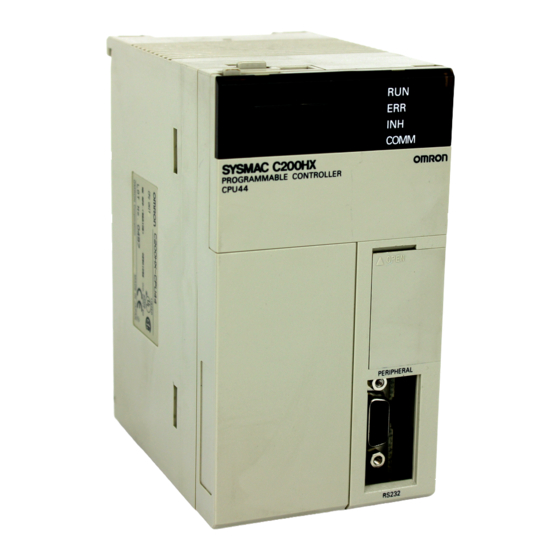
Units Section 2-2 2-1-3 I/O Connecting Cable The first Expansion I/O Rack is connected to the CPU Rack, and the second and third Expansion I/O Racks are connected to the previous Expansion I/O Rack through I/O Connecting Cable. There are five different lengths of cable avail- able, which can be used as desired to provide the desired distance between each Rack. - Page 30 Units Section 2-2 1, 2, 3... 1. Indicators The indicators (LEDs) on the front cover of the CPU Unit operate as described in the following table. Contents RUN (green) Lights when the PC is operating normally in MONITOR or RUN mode. ERR (red) Flashes if an error occurs that does not stop the CPU Unit (a non-fatal error).
- Page 31 Units Section 2-2 3. DIP Switch The DIP switch is used to make various settings that determine who the PC will operate. The C200HX/C200HG/C200HE CPU Unit has a 6-pin DIP switch, as shown in the following diagram. The settings of these pins are listed in the following table.
-
Page 32: Memory Cassettes
Units Section 2-2 tions Board. Refer to 3-1-9 Mounting a Communications Board for the mounting methods. 2-2-2 Memory Cassettes Memory Cassettes can be optionally mounted to increase memory capacity over just the built-in RAM. There are two types of Memory Cassette available. These are shown in the following diagram. -
Page 33: Communications Boards
Units Section 2-2 2-2-3 Communications Boards An optional Communications Board can be mounted in the CPU Unit to provide communications with the following types of devices/systems through the com- munications port: SYSMAC LINK Systems, SYSMAC NET Systems, personal computers, Programmable Terminals (PTs), bar code readers, temperature controllers, devices with RS-232C or RS-422 interfaces, etc. -
Page 34: Power Supply Units
Units Section 2-2 Note Use either the C200HW-COM01 or a V1 Communications Board for the ZE-ver- sion C200HX/HG/HE CPU Units. Indicators (LEDs) The Communications Board indicators on the front panel of the CPU Unit indi- cate the status of the Board, as described in the following table. Indicator Color Status... - Page 35 Units Section 2-2 2. Terminals for External Connections These terminals are connected as shown in the diagram below. The num- bers in the diagram correspond to the numbers of the following items in the description. Supply Output Output RUN output Model voltage capacity...
- Page 36 Units Section 2-2 Terminal Connections C200HW-PA204: AC Input C200HW-PA204S: AC Input 1. AC Input 100 to 120 VAC/ 100 to 120 VAC/ 1. AC Input 200 to 240 VAC 200 to 240 VAC Input Input Voltage selector 100 to 120 Voltage selector 100 to 120 Close...
- Page 37 Units Section 2-2 4. GR Ground the GR terminal to 100 Ω or less to protect against possible electri- cal shock. 5. 24 VDC Output (C200HW-PA204S Only) The 24 VDC output terminals can be used to supply power to DC Input Units. The combined power consumption for both 5 V and 24 V must be 30 W or less.
- Page 38 Units Section 2-2 Restrictions for the Use the C200HW-PA204R/PA209R Power Supply Unit only with the following C200HW-PA204R/PA209R CPU Units and Backplanes. CPU Units and Backplanes with manufacturing numbers earlier than the ones given cannot be used. CPU Units Manufacturing number (See below.) Model Made in Japan Made in the Netherlands...
-
Page 39: Backplanes
Units Section 2-2 2-2-5 Backplanes There are two types of Backplane: the CPU Backplane, used for the CPU Rack, and the I/O Backplane, used for Expansion I/O Racks. The Backplane serves to hold and connect the following types of Unit: the CPU Unit, the Power Supply Unit, I/O Units, Special I/O Units, etc. -
Page 40: Standard I/O Units
Units Section 2-2 2-2-6 Standard I/O Units The following Standard I/O Units are available. Input Units Name Model number Specifications No. of points DC Input Unit C200H-ID211 12 to 24 VDC 8 pts C200H-ID212 24 VDC 16 pts AC Input Unit C200H-IA121 100 to 120 VAC 8 pts... - Page 41 Units Section 2-2 Components The Standard I/O Units come in three shapes; A-shape, B-shape, and E-shape. Refer to Appendix D Specifications for the dimensions of each Unit. The num- bers in the diagram correspond to the numbers of the following items in the description.
-
Page 42: Group-2 High-Density I/O Units
Units Section 2-2 1, 2, 3... 1. I/O Unit Lock Notch The lock notch fits into the Backplane to hold the Unit in place. 2. Nameplate The nameplate shows the model number of the I/O Unit. 3. I/O Indicators (LEDs) The indicators show the ON/OFF status of the I/O points. - Page 43 Units Section 2-2 Unit Specifications Shape Model DC Input Unit 12 VDC; 64 pts C200H-ID111 C200H-ID217 24 VDC; 32 pts C200H-ID218 24 VDC; 64 pts C200H-ID216 C200H-ID219 Transistor Output Unit 4.5 VDC,16 mA to C200H-OD218 26.4 VDC,100 mA; 32 pts 4.5 VDC,16 mA to C200H-OD219 26.4 VDC,100 mA;...
- Page 44 Units Section 2-2 1, 2, 3... 1. I/O Unit Lock Notch The lock notch fits into the Backplane to hold the Unit in place. 2. Nameplate The nameplate shows the model number of the I/O Unit. 3. I/O Indicators (LED) The indicators show the ON/OFF status of the I/O points.
-
Page 45: High-Density I/O Units Classified As Special I/O Units
Units Section 2-2 2-2-8 High-density I/O Units Classified as Special I/O Units Some High-density I/O Units are classified as Special I/O Units. Up to 10 or up to 16 Special I/O Units can be connected to a PC depending on the CPU Unit that is used. -
Page 46: Peripheral Devices
Peripheral Devices Section 2-3 Peripheral Devices There are various Peripheral Devices that can be use to support C200HX/ C200HG/C200HE operation. These Peripheral Devices are introduced in this section. 2-3-1 Programming Consoles There are two Programming Consoles that can be used with the C200HX/ C200HG/C200HE: the C200H-PRO27-E and the CQM1-PRO01-E. -
Page 47: Cx-Programmer
Peripheral Devices Section 2-3 2-3-2 CX-Programmer The CX-Programmer is a Programming Device that runs on Windows. It is used for full-scale programming operations. Use the following Connecting Cables to connect the computer running the CX-Programmer with the C200HX/HG/ HE(-Z) PCs. Connecting Cables for C200HX/HG/HE(-Z) PCs Unit Unit port... -
Page 48: Expanded System Configurations
Expanded System Configurations Section 2-4 Expanded System Configurations 2-4-1 Required Mounting Conditions A maximum of 16 Special I/O Units including PC Link Units can be mounted to any slot of CPU, Expansion I/O, and Slave Racks. I/O word numbers 100 to 199, 400 to 459, and DM 1000 to DM 2599 are allocated to each Special I/O Unit. - Page 49 Expanded System Configurations Section 2-4 The C200H-MD501, C200H-MD115, and C200H-MD215 can each be set for 128 dynamic input points (64 points x two circuits) and the C200H-OD501 and C200H-OD215 can each be set for 128 dynamic output points (64 points x two circuits).
- Page 50 Expanded System Configurations Section 2-4 Analog I/O Units The Analog Input (A/D) Units retrieve analog inputs and the Analog Output (D/A) Unit sends analog outputs. The following Analog I/O Units are available: C200H-AD001 with 4-point analog input, C200H-AD002 with 8-point analog input, C200H-DA001 with 2-point analog output, and C200H-DA002 with 4-point analog output The Analog Input (AD) Unit is used.
- Page 51 Expanded System Configurations Section 2-4 Voice Unit Voice messages can be input from dynamic microphones or cassette tape recorders and output from loudspeakers or headsets via the Voice Unit. The Voice Unit incorporates a sentence function and word combination function, either of which can be selected to record voice messages for 64 seconds maxi- mum.
- Page 52 Expanded System Configurations Section 2-4 Fuzzy Logic Unit The C200H-FZ001 Fuzzy Logic Unit incorporates a high-functional fuzzy Logic processor and allows high-speed fuzzy logic. A personal computer can be connected to the Fuzzy Logic Unit via RS-232C cables for software development and monitoring. Use the C500-SU981-E Fuzzy Support Software for IBM PC/AT or compatible personal computers.
- Page 53 Expanded System Configurations Section 2-4 Cam Positioner Unit A single C200H-CP114 Cam Positioner Unit is as powerful as 48 mechanical cams because it can complete jobs that normally require 48 mechanical cams. It is possible to set 16-point external output and 32-point internal output as cam output.
- Page 54 Expanded System Configurations Section 2-4 PID Control Unit The PID Control Unit scales inputs from connected sensors and then carries out PID control according to preset control mode. Select the control output of the PID Control Unit from the following. Model Control output C200H-PID01...
-
Page 55: Link Systems And Networks
B7A Interface Unit. Specifications for all of these Units are provided in Appendix B Specifications. SYSMAC LINK Systems OMRON’s SYSMAC LINK System is a communications network that connects up to 62 nodes to provide data links, data transfers, and datagram services. CPU Unit... - Page 56 Expanded System Configurations Section 2-4 SYSMAC NET Link Systems OMRON’s SYSMAC NET Link System is an FA-oriented limited-area network that connects up to 126 nodes to provide datagram services, data transfers, and data links. SYSMAC NET Link Unit C200HS-SNT32 CPU Unit...
- Page 57 Expanded System Configurations Section 2-4 Host Link Systems A maximum of two Host Link Units can be mounted to slots in either the CPU Rack or an Expansion I/O Rack. The following Host Link Units are available: C200H-LK101-PV1 (optical cable) C200H-LK201-PV1 (RS-232C) C200H-LK202-V1 (RS-422) For details, refer to the SYSMAC C-series Rack PCs SYSMAC WAY - Host Link...
- Page 58 Expanded System Configurations Section 2-4 CompoBus/S Systems The CompoBus/S is a high-speed I/O data communications system designed to meet the needs of time-critical FA applications. I/O Terminal CompoBus/S Master Unit Sensor Terminal Bit Chain Terminal • The CompoBus/S Master Unit is mounted to the CPU Rack or an Expansion I/O Rack.
- Page 59 Expanded System Configurations Section 2-4 DeviceNet Systems The DeviceNet is an I/O data communications system conforming to the Device- Net standard being developed to standardize device-level networks for FA. CQM1 (I/O Link Unit) DeviceNet Master Unit I/O Terminal Adapter Sensor Terminal Analog Input Terminal Analog Output Terminal •...
- Page 60 Expanded System Configurations Section 2-4 Remote I/O Systems A maximum of two Optical or Wired Remote I/O Master Units can be mounted to slots in either the CPU Rack or an Expansion I/O Rack. A maximum total of five Slave Racks, each with a single Slave Unit, can be connected. C500 Slave Racks can be used, but each C500 Slave Rack must be counted as two Racks in calculating the total.
- Page 61 Expanded System Configurations Section 2-4 Controller Link Systems Controller Link Units can be mounted to C200HX/HG/HE CPU Racks to create automatic data links that can be freely set between C200HX/HG/HE, CVM1, and/or CV-series PCs. Controller Link Support Boards are also available so that IBM PC/AT or compatibles can also be included in the Controller Link System.
- Page 62 Expanded System Configurations Section 2-4 PC Card Unit The PC Card Units allows you to expand PC capabilities by adding a PC card. The PC card can be used to save and retrieve CIO, DM, EM, and other data area contents between the CPU Unit and the PC card from the ladder-diagram pro- gram (using the CMCR instruction).
-
Page 64: Installation And Wiring
SECTION 3 Installation and Wiring This section describes how to install a PC System, including mounting the various Units and wiring the System. Be sure to follow the instructions carefully during installing. Improper installation can cause the PC to malfunction, resulting in extremely dangerous situations. -
Page 65: Installation Environment
Section 3-1 Installation Environment Installation Environment This section details the necessary environmental conditions for installing the PC. Proper installation procedures and a proper environment are essential to getting the best performance and reliability from your PC. Caution Static electricity can damage PC components. Your body can carry an electros- tatic charge, especially when the humidity is low. -
Page 66: Installing Racks
Section 3-1 Installation Environment Cooling Fan A cooling fan is not always necessary, but may be needed in some installations. Try to avoid mounting the PC in a warm area or over a source of heat. A cooling fan is needed if the ambient temperature may become higher than that speci- fied. - Page 67 Section 3-1 Installation Environment Note Tighten the PC Rack mounting screws, terminal block screws, and cable screws to the torque of 1.2 N S m. Caution Racks must be mounted horizontally so that the Units are upright (i.e., not upside down or lying on their backs).
-
Page 68: Mounting Height
Section 3-1 Installation Environment gap of at least 80 mm between the top of the Power Supply Unit and the top of the panel, wiring ducts, parts, or any other structures. Ducts, etc. 80 mm min. C200HW-PA209R 80 mm min. Ducts, etc. -
Page 69: Mounting Dimensions (Units: Mm)
Section 3-1 Installation Environment 3-1-4 Mounting Dimensions (Units: mm) Backplanes A±0.2 Four, M4 CPU Backplane 118±0.2 68 to 108 80 to 120 118±0.2 I/O Backplane Four, M4 Model CPU Backplane C200HW-BC031 246 mm 260 mm C200HW-BC051 316 mm 330 mm C200HW-BC081-V1 421 mm 435 mm... -
Page 70: Din Track Mounting
PC may be directly mounted to any sturdy support meeting the environmental specifications (refer to Appendix B Specifications). If you want to mount the PC on DIN track, you can order a DIN Track from OMRON (refer to Appendix B Standard Models). DIN Tracks come in the two heights shown below. - Page 71 Section 3-1 Installation Environment DIN Track Mounting Bracket The DIN Track Mounting Bracket shown below is necessary for mounting the PC to the DIN Track. DIN Track The following DIN Tracks are available. Model Specification PFP-50N 50 cm long, 7.3 mm high PFP-100N 1 m long, 7.3 mm high PFP-100N2...
- Page 72 Section 3-1 Installation Environment 2. Mount the Backplane to the DIN Track so that the claws on the Mounting Brackets fit into the upper portion of the DIN Track as shown below. This claw fits into the DIN Track DIN Track Backplane DIN Track Mounting Bracket 3.
-
Page 73: Mounting Units To The Backplane
Section 3-1 Installation Environment 3-1-6 Mounting Units to the Backplane The CPU Unit of the C200HX/C200HG/C200HE has no I/O points built in. In order to complete the PC it is necessary to mount at least one or more I/O Units to the Backplane. - Page 74 Section 3-1 Installation Environment CPU Units, I/O Power Supply Units and Slave Units must have the screws on the bottom tightened with a Phillips screwdriver. The screwdriver must be held at a slight angle, so be sure to leave enough space below each Rack. Duct 20 mm min.
-
Page 75: I/O Connecting Cables
Section 3-1 Installation Environment 3-1-7 I/O Connecting Cables Each Rack must be mounted vertically, that is with the printing on the front pan- els oriented as it would normally be read. The Racks should be mounted one above the other with the CPU Rack uppermost as shown below. The C200HX/HG/HE is approved by Underwriters Laboratories under the condi- tion that, “The device must be mounted vertically for ventilation purposes.”... -
Page 76: Mounting Memory Cassettes
Section 3-1 Installation Environment 3-1-8 Mounting Memory Cassettes Use the following procedure to mount a Memory Cassette. Caution Be careful to always turn the power off before inserting or removing a Memory Cassette. If a Memory Cassette is inserted into or removed from the CPU Unit with the power on, it may cause the CPU Unit to malfunction or cause damage to the memory. -
Page 77: Mounting A Communications Board
Section 3-1 Installation Environment 3-1-9 Mounting a Communications Board Caution Be careful to always turn the power off before inserting or removing a Commu- nications Board. If a Communications Board is inserted into or removed from the CPU Unit with the power on, it may cause the CPU Unit to malfunction, cause damage to the memory, or cause errors in communications. -
Page 78: Wiring
Wiring Section 3-2 4. Close the compartment covers. Wiring 3-2-1 Power Supply Wiring AC Power Supply Units Note 1. Do not remove the protective label from the top of the Unit before wiring. This label is to prevent wiring clippings and other foreign matter from entering the Unit during wiring procedures. - Page 79 Wiring Section 3-2 C200HW-PA204R or C200HW-PA209R Power Supply Unit Screw (3.5 mm head with self-raising pressure plate) 1:1 isolation transformer AC power Voltage selector source RUN output OUTPUT Power supply AC Power Source • Supply 100 to 120 or 200 to 240 VAC. •...
- Page 80 Wiring Section 3-2 The output voltage of the 24-VDC output will vary with the current consumption of the load as shown in the following table. Be sure to check the current con- sumption and allowable voltage ranges of the devices connected before using these terminals.
- Page 81 Wiring Section 3-2 RUN Output These terminals turn ON whenever the CPU Unit is operating in RUN or MON- ITOR Mode. Use these terminals under the following specifications These termi- nals are available on the C200HW-PA204R/PA209R only. Model C200HW-PA204R C200HW-PA209R Contact SPST-NO form...
- Page 82 Wiring Section 3-2 DC Power Source Supply 24 VDC. Keep voltage fluctuations within the specified range (19.2 to 28.8 V). Power Consumption The power consumption will be 40 W max. per Rack, and there will be a surge current of at least 5 times the max. power when power is turned on. Crimp Terminals The terminals on the Power Supply Unit are M3.5, self-raising terminals with screws.
-
Page 83: Standard I/O Unit Wiring
Wiring Section 3-2 When using an Expansion I/O Rack, the Rack must also be grounded to the GR terminal. The same ground can be used for all connections. Wrong Other Other Other devices devices devices Ground to 100 Ω or less. Ground to 100 Ω... - Page 84 Wiring Section 3-2 Wiring Be sure that each Unit is securely mounted. In order to prevent wire scraps and other objects from getting inside of the Unit, keep the top-surface label on while wiring the Unit. After the wiring has been completed, be sure to remove the label in order to allow heat radiation.
- Page 85 Wiring Section 3-2 I/O Unit Covers A C200H-COV11 Cover is provided as an I/O Unit cover for Units that use 10P terminal block connectors. After the I/O wiring has been completed, slide the cover up from the bottom, as shown in the illustration below. These Covers should be applied whenever the extra protection is required.
- Page 86 Wiring Section 3-2 The circuit below should be used for I/O devices having a voltage output. Voltage output Output DC Input Unit Sensor Power Supply The circuit below should NOT be used for I/O devices having a voltage output. Voltage output Sensor Power Supply...
- Page 87 Wiring Section 3-2 For standard I/O Units: I = leakage current in mA kΩ max. –––––– 2.4 x I – 3 W min. ––– The previous calculations are based on the following equations. Input voltge (24) Input current (10) v OFF voltage (3) Input voltage (24) Input current (10) Input voltage (24)
- Page 88 Wiring Section 3-2 3. Relation between current when the PC is OFF and sensor leakage current: leak Refer to Input Leakage Current later in this section for details. The I values differ for each Unit, but is always 1.3 mA for Input Units whose OFF current specifications are not given.
-
Page 89: Electrical Noise
Wiring Section 3-2 Output Surge Current When connecting a transistor or triac Output Unit to an output device having a high surge current (such as an incandescent lamp), care must be taken to avoid damage to the Output Unit. The transistor and triac Output Units are capable of withstanding a surge current of ten times the rated current. - Page 90 Wiring Section 3-2 Inductive Load Surge Suppressor When an inductive load is connected to an I/O Unit, it is necessary to connect a surge suppressor or diode in parallel with the load as shown below. This is so that the back EMF generated by the load will be absorbed. Diode DC input Contact Output Unit...
- Page 91 Wiring Section 3-2 External Wiring If power cables must be run alongside the I/O wiring (that is, in parallel with it), at least 300 mm must be left between the power cables and the I/O wiring as shown below. Low current cable 300 mm min.
- Page 92 Wiring Section 3-2 This circuit prevents outputs MC1 and MC2 from ever both being ON at the same time. Even if the PC is programmed improperly or malfunctions, the motor is pro- tected. Using the Antinoise Insulating Attachment When using the C200HX/HG/HE CPU Unit near a power supply system, unwanted current paths may cause operating errors.
- Page 93 Wiring Section 3-2 between 10 and 25 ms (between 2 and 5 ms for a DC Power Supply), the inter- ruption may or may not be detected. If the supply voltage drops below 85% of the rated voltage for longer that 25 ms (less for the DC Power Supply), the PC will stop operating and the external outputs will be automatically turned OFF.
-
Page 94: Programming Console Operation
SECTION 4 Programming Console Operation This section describes the function of the Programming Console and its connection methods. Using the Programming Console ..........4-1-1 Nomenclature . -
Page 95: Using The Programming Console
Section 4-1 Using the Programming Console Using the Programming Console 4-1-1 Nomenclature The front panel of the Programming Console is shown below, taking the C200H-PRO27-E as an example. C200H-PRO27-E Programming Console LCD area Mode selector switch Instruction keys Numeric keys Operation keys Cassette jacks LCD Area... -
Page 96: Connecting The Programming Console
Section 4-1 Using the Programming Console 4-1-2 Connecting the Programming Console There are two Programming Console models that can be used with the C200HX/ C200HG/C200HE: the C200H-PRO27-E and the CQM1-PRO01-E. The follow- ing illustration shows how a Programming Console (a C200H-PRO27-E in this case) connects to the C200HX/C200HG/C200HE CPU Unit. -
Page 97: Checking Initial Operation
Checking Initial Operation Section 4-2 Checking Initial Operation After the Programming Console has been connected, it can be used to check initial C200HX/C200HG/C200HE operation. Make sure that the Programming Console is properly connected and that the correct power supply is being pro- vided, and then follow the procedure outlined below. -
Page 98: Troubleshooting, Inspections, And Maintenance
SECTION 5 Troubleshooting, Inspections, and Maintenance The C200HX/C200HG/C200HE provides self-diagnostic functions to identify many types of abnormal system conditions. These functions minimize downtime and enable quick, smooth error correction. This section provides information on hardware and software errors that occur during PC operation. It also provides inspection and maintenance information that can be used to help prevent the occurrence of errors. -
Page 99: Troubleshooting
Section 5-1 Troubleshooting Troubleshooting CPU Racks and Expansion I/O Racks Error Probable cause Possible correction POWER indicator does not light. The voltage selector terminal setting is Correct the voltage selector terminal wrong. (A 100-VAC voltage is used setting. when set to 200 VAC.) The 24-V output terminals are Correct the wiring. - Page 100 Section 5-1 Troubleshooting Input Units Error Probable cause Possible correction Indicator lights are turned off, and no No external input power supply is Provide a power supply. inputs turn ON. pu s u provided. The external input voltage is low. Supply the rated voltage.
- Page 101 Section 5-1 Troubleshooting Output Units Error Probable cause Possible correction No outputs turn ON. A load power supply is not provided. Provide the power supply. The load power supply voltage is low. Provide the rated voltage. Terminal screws are loose. Tighten the terminal screws.
-
Page 102: Inspection And Maintenance
Inspection and Maintenance Section 5-2 Inspection and Maintenance 5-2-1 Replacing Output Unit Fuses The following Output Units each contain one fuse. Replace the fuse if the fuse indicator lights. The OD211, OD212, OA222, and OA224 Output Units do not have fuse indicators. Replace the fuses on these Units if outputs are not pro- duced. -
Page 103: Replacing Relays
1. Use UL or CSA approved fuses if the UL or CSA standards must be satis- fied. For further details, consult the fuse manufacturer. 2. Fuses in High-density I/O Units cannot be replaced by the user. Refer to your OMRON dealer for service. 5-2-2 Replacing Relays Replacement Relay The following Output Units provide relay sockets that allow the Relays to be replaced if they should go bad. - Page 104 Inspection and Maintenance Section 5-2 3. While pushing down the lock lever on the Backplane with a screwdriver as shown below, remove the Output Unit. Lock lever 4. Using a Phillips screwdriver, remove the screw from the top of the Unit. 5.
- Page 105 Inspection and Maintenance Section 5-2 Caution Check the pin arrangement before inserting a new Relay into the socket. Pins can only be inserted one way, so do not try to force them if they do not go in easily. Applying too much force can bend the pins and render them unusable. OC221/OC224 OC222 OC223...
-
Page 106: Batteries
Inspection and Maintenance Section 5-2 OC224V OC226 Note The relays on the C200H-OC222N, C200H-OC224V, and C200H-OC226 can- not be replaced. 5-2-3 Batteries DANGER Batteries can burn, explode, or leak. Absolutely do not short-circuit across the terminals, attempt to recharge batteries, or take them apart, heat them, or expose them to fire. -
Page 107: Inspections
• When returning a Unit for repairs, provide as many details about the problem as possible in writing and attach it to the Unit before delivering it to your OMRON representative. (See inside back cover for regional offices.) • To clean bad contacts, use a clean cotton cloth soaked in industrial alcohol and... - Page 108 Inspections Section 5-3 Inspection Tools • Required Tools • Screwdrivers (flat-blade and Phillips) • Voltage tester (analog or digital) • Industrial alcohol and a clean cotton cloth • Tools Required in Special Cases • Synchroscope • Oscilloscope with pen plotter •...
-
Page 110: A Standard Models
Appendix A Standard Models CPU Rack Name Specifications Model number CPU Units (All models are pro- I/O points RS-232C vided with clock function and slots id d i h l None 3.2K words C200HE-CPU11-E/ZE for communications except for communications except 7.2K words C200HE-CPU32-E/ZE CPU11-E/ZE.) - Page 111 Appendix A Standard Models Name Specifications Model number CPU Backplanes 3 slots C200HW-BC031 5 slots C200HW-BC051 8 slots (see note) C200HW-BC081-V1 10 slots (see note) C200HW-BC101-V1 Note There are restrictions in combining Backplanes and Power Supply Units when using the C200HW-PA209R Power Supply Unit with an 8-slot or 10-slot CPU Backplane or Expansion I/O Backplane.
- Page 112 Appendix A Standard Models Expansion I/O Racks Name Specifications Model number Power Supply Units pp y 100 to 120/200 to 240 VAC C200HW-PA204 100 to 120/200 to 240 VAC (with 24-VDC output terminals) C200HW-PA204S 100 to 120/200 to 240 VAC C200HW-PA204R 100 to 120/200 to 240 VAC C200HW-PA209R...
- Page 113 Appendix A Standard Models I/O Units Name Specifications Model number Input Units AC Input Units 8 pts 100 to 120 VAC C200H-IA121 16 pts 100 to 120 VAC C200H-IA122/IA122V 8 pts 200 to 240 VAC C200H-IA221 16 pts 200 to 240 VAC C200H-IA222/IA222V DC Input Units 8 pts...
- Page 114 Appendix A Standard Models Name Specifications Model number B7A Interface Units 15 or 16 Connects to B7A Link Terminals. Standard C200H-B7AI1 input pts transmission delay. Connects to B7A Link Terminals. Standard C200H-B7AO1 (see output transmission delay. note) Note 1. If the Interrupt Input Unit is mounted on an Expansion I/O Rack, the interrupt function cannot be used and the Interrupt Input Unit will be treated as an ordinary 8-point Input Unit.
- Page 115 Appendix A Standard Models Special I/O Units Name Specifications Model number High-density DC Input Units 32 pts 5 VDC (TTL inputs); w/high-speed input C200H-ID501 I/O U i I/O Units 32 pts 24 VDC; w/high-speed input C200H-ID215 (see note 1) (see note 1) Transistor Output 32 pts 0.1 A, 24 VDC (useable as 128-point...
- Page 116 Appendix A Standard Models Name Specifications Model number Cam Positioner Unit Detects angles of rotation by means of a resolver and C200H-CP114 provides ON and OFF outputs at specified angles. A maximum of 48 cam outputs (16 external outputs and 32 internal outputs) maximum are available.
- Page 117 3. Observe the following points when using the C200H-OV001 Voice Unit: • The C200H-OV001 Voice Unit cannot be used when an OMRON display device (Programmable Termi- nal) is connected to the peripheral port or the RS-232C port of a C200HX/HG/HE(-Z) CPU Unit in NT Link mode.
- Page 118 Appendix A Standard Models Communication Units Name Specifications Model number SYSMAC LINK Unit A Bus Connection Unit must be ordered Data link table: C200HW-SLK23 (coaxial cable) separately. sepa a e y 918 words Data link table: C200HW-SLK24 2,966 words Terminator One required for each node at ends of System.
- Page 119 Appendix A Standard Models Name Specifications Model number Remote I/O Master Up to two per PC; connectable to up to 5 Slaves APF/PCF C200H-RM001-PV1 Units per PC total Wired C200H-RM201 Remote I/O Slave Units See Racks at beginning of product lists. Controller Link Unit Enables data link and message communications.
- Page 120 The boxes (jjj) are replaced by codes indicating the standard model lengths, as shown below. Consult with your OMRON representative for longer cables. When ordering longer cables, omit the portion represented by the boxes and specify the length in meters separately, e.g., S3200-CN-20-20, 30 m.
- Page 121 Appendix A Standard Models Applicable Optical Fiber Connectors Applicable Units Model number/Appearance SYSMAC NET SYSMAC LINK S3200-COCF2011 CV500-SNT31 CV500-SLK11 C1000H-SLK11 S3200-COCF2511 C200HS-SNT32 C200HW-SLK13/14 S3200-COCH62M S3200-LSU03-01E S3200-NSUA1-00E S3200-NSUG4-00E S3200-NSB11-E C500-SNT31-V4 B700-AL001 All Plastic Optical Fiber Cable for SYSMAC BUS/SYSMAC WAY Name Specifications Model number Standards...
- Page 122 Appendix A Standard Models H-PCF Optical Fiber Cables (For SYSMAC NET, SYSMAC LINK, and SYSMAC BUS) Name Specifications Model number Stan- dards Optical Fiber Cables 10 m, black Composite S3200-HCLB101 SYSMAC NET SYSMAC LINK SYSMAC NET, SYSMAC LINK cable including cable including S3200-HCLB501 50 m, black...
- Page 123 Appendix A Standard Models 2. If the user prepares and connects optical fiber cables, the user must take a seminar held under the aus- pices of Sumitomo Electric Industries, Ltd. and obtain a proper certificate. 3. The Optical Power Tester, Head Unit, Master Fiber Set, and Optical Fiber Assembling Tool are required to connect optical fiber cables.
- Page 124 Appendix A Standard Models Note: Use a proper Head Unit model for the optical module to be used. If two types of optical modules (unit type and board type) are used, order an Optical Power Tester plus a proper Head Unit model. Master Fiber Set Name Specifications...
- Page 125 Appendix A Standard Models Optional Products Name Specifications Model number Standards I/O Unit Cover Cover for 10-pin terminal block C200H-COV11 Terminal Block Cov- Short protection for 10-pin terminal block (package of 10 cov- C200H-COV02 ers); 8 pts Short protection for 19-pin terminal block (package of 10 cov- C200H-COV03 ers);...
- Page 126 Appendix A Standard Models Mounting Rails and Accessories Name Specifications Model number Standards DIN Track Mounting 1 set (2 included) C200H-DIN01 Bracket DIN Tracks Length: 50 cm; height: 7.3 cm PFP-50N Length: 1 m; height: 7.3 cm PFP-100N Length: 1 m; height: 16 mm PFP-100N2 End Plate PFP-M...
-
Page 128: B Specifications
Appendix B Specifications The following figures and tables provide specifications for each Unit of the C200HX/C200HG/C200HE. I/O Units may take on one of two different shapes and are sometimes referred to as A-shape Units or B-shape Units. Group-2 High-density I/O Units take on one of two different shapes and are sometimes referred to as C-shape Units or D-shape Units. - Page 129 Appendix B Specifications Power Supply C200HW-PA204 C200HW-PA204S C200HW-PA204R C200H-PA209R C200HW-PD024 Unit 1,500 Vp-p, pulse width: 100 ns to 1 µs, rise time: 1 ns pulse (by noise simulator) Noise immunity Vibration JIS C0040 conforming,10 to 57 Hz; 0.075 mm amplitude, 57 to 150 Hz (see note 3); acceleration: resistance 9.8 m/s , in X, Y, and Z directions, for 80 minutes each (sweep time 8 min x 10 sweeps = 80 min);...
- Page 130 Appendix B Specifications 3. Vibration Resistance Acceleration (m/s Amplitude 0.075 mm Frequency (Hz) 4. Dimensions (Unit: mm) 5. RUN output is only available when the Power Supply Unit is mounted on the CPU Backplane.
- Page 131 Appendix B Specifications CPU Unit Specifications Control Method Stored program I/O Control Cyclic scan and immediate processing are both possible. Method Programming Ladder diagram Method Instruction Length 1 address/instruction, 1 to 4 words/instruction Number of C200HE-CPUjj-E: 14 basic instructions + 231 special instructions Instructions C200HE-CPUjj-ZE: 14 basic instructions + 286 special instructions C200HE-CPUjj-E/ZE: 0.3 µs min.
- Page 132 Signal Shielded cable Applicable Connectors The following connectors are applicable. One plug and one hood are included with the CPU Unit. Plug: XM2S-0901 (OMRON) or equivalent Hood: XM2S-0911 (OMRON) or equivalent Port Specifications Item Specification Communications method Half duplex Sync...
- Page 133 Appendix B Specifications One-to-one Link Connections The RS-232C port on the C200HX/C200HG/C200HE can be connected to the same port on another C200HX/C200HG/C200HE. Wire the cable as shown in the diagram below. C200HE/C200HG/C200HX C200HE/C200HG/C200HX Signal Signal Abb. Abb. – Ground the FG terminals of C200HX/C200HG/C200HE Units at a resistance of less than 100 Ω.
- Page 134 Appendix B Specifications C200H Standard I/O Units Name Specifications Model number Shape Input DC Input Units 8 pts 12 to 24 VDC C200H-ID211 Units 16 pts 24 VDC C200H-ID212 AC Input Unit 8 pts 100 to 120 VAC C200H-IA121 16 pts 100 to 120 VAC C200H-IA122/IA122V 8 pts...
- Page 135 Appendix B Specifications Optional Products Name Specifications Model number I/O Unit Cover Terminal cover for 8-point or 5-point I/O Units C200H-COV11 Connector Cover Protective cover for unused Backplane connectors C500-COV01 Space Unit Used to hold space for an I/O Unit. C200H-SP001 Note 1.
- Page 136 Appendix B Specifications DC Input Unit C200H-ID212 Rated Input Voltage 24 VDC Operating Input Voltage 20.4 to 26.4 VDC Input Impedance 3 kW Input Current 7 mA (at 24 VDC) ON Voltage 14.4 VDC min. OFF Voltage 5.0 VDC max. ON Response Time 1.5 ms max.
- Page 137 Appendix B Specifications AC Input Unit C200H-IA121 Rated Input Voltage 100 to 120 VAC 50/60 Hz Operating Input Voltage 85 to 132 VAC 50/60 Hz Input Impedance 9.7 kW (50 Hz), 8 kW (60 Hz) Input Current 10 mA typical (at 100 VAC) ON Voltage 60 VAC min.
- Page 138 Appendix B Specifications AC Input Unit C200H-IA122/IA122V Rated Input Voltage 100 to 120 VAC 50/60 Hz Operating Input Voltage 85 to 132 VAC 50/60 Hz Input Impedance 9.7 kW (50 Hz), 8 kW (60 Hz) Input Current 10 mA typical (at 100 VAC) ON Voltage 60 VAC min.
- Page 139 Appendix B Specifications AC Input Unit C200H-IA221 Rated Input Voltage 200 to 240 VAC 50/60 Hz Operating Input Voltage 170 to 264 VAC 50/60 Hz Input Impedance 21 kW (50 Hz), 18 kW (60 Hz) Input Current 10 mA typical (at 200 VAC) ON Voltage 120 VAC min.
- Page 140 Appendix B Specifications AC Input Unit C200H-IA222/IA222V Rated Input Voltage 200 to 240 VAC 50/60 Hz Operating Input Voltage 170 to 264 VAC 50/60 Hz Input Impedance 21 kW (50 Hz), 18 kW (60 Hz) Input Current 10 mA typical (at 200 VAC) ON Voltage 120 VAC min.
- Page 141 Appendix B Specifications AC/DC Input Unit C200H-IM211 Rated Input Voltage 12 to 24 VDC Operating Input Voltage 10.2 to 26.4 VDC Input Impedance 2 kW Input Current 10 mA typical (at 24 VDC) ON Voltage 10.2 VDC min. OFF Voltage 3.0 VDC max.
- Page 142 Appendix B Specifications AC/DC Input Unit C200H-IM212 Rated Input Voltage 24 VDC Operating Input Voltage 20.4 to 26.4 VDC Input Impedance 3 kW Input Current 7 mA typical (at 24 VDC) ON Voltage 14.4 VDC min. OFF Voltage 5.0 VDC max. ON Response Time 15 ms max.
- Page 143 Appendix B Specifications Contact Output Unit C200H-OC221 Max. Switching Capacity 2 A 250 VAC (cosf = 1), 2 A 250 VAC (cosf = 0.4), 2 A 24 VDC (8 A/Unit) Min. Switching Capacity 10 mA 5 VDC Relay G6B-1174P-FD-US (24 VDC) w/socket Service Life of Relay Electrical: 500,000 operations (resistive load)/ 100,000 operations (inductive load)
- Page 144 Appendix B Specifications Contact Output Unit C200H-OC222 Max. Switching Capacity 2 A 250 VAC (cosf = 1), 2 A 250 VAC (cosf = 0.4), 2 A 24 VDC (8 A/Unit) Min. Switching Capacity 10 mA 5 VDC Relay G6B-1174P-FD-US (24 VDC) w/socket Service Life of Relay Electrical: 500,000 operations (resistive load)/ 100,000 operations (inductive load)
- Page 145 Appendix B Specifications Contact Output Unit C200H-OC225 Max. Switching Capacity 2 A 250 VAC (cosf = 1), 2 A 250 VAC (cosf = 0.4), 2 A 24 VDC (8 A/Unit) Min. Switching Capacity 10 mA 5 VDC Relay G6B-1174P-FD-US (24 VDC) w/socket Service Life of Relay Electrical: 500,000 operations (resistive load)/ 100,000 operations (inductive load)
- Page 146 Appendix B Specifications Contact Output Unit C200H-OC223 Max. Switching Capacity 2 A 250 VAC (cosf = 1), 2 A 250 VAC (cosf = 0.4), 2 A 24 VDC (10 A/Unit) Min. Switching Capacity 10 mA 5 VDC Relay G6B-1174-P-FD-US (24 VDC) w/socket Service Life of Relay Electrical: 500,000 operations (resistive load)/ 100,000 operations (inductive load)
- Page 147 Appendix B Specifications Contact Output Unit C200H-OC224 Max. Switching Capacity 2 A 250 VAC (cosf = 1), 2 A 250 VAC (cosf = 0.4), 2 A 24 VDC (16 A/Unit) Min. Switching Capacity 10 mA 5 VDC Relay G6B-1174-P-FD-US (24 VDC) w/socket Service Life of Relay Electrical: 500,000 operations (resistive load)/ 100,000 operations (inductive load)
- Page 148 Appendix B Specifications Contact Output Unit C200H-OC222V/OC222N Max. Switching Capacity 2 A 250 VAC (cosf = 1), 2 A 250 VAC (cosf = 0.4), 2 A 24 VDC (8 A/Unit) Min. Switching Capacity 10 mA 5 VDC Relay OC222V: G6R-1 (24 VDC) w/socket OC222N: G6RN-1-ACD (24 VDC) soldered to board Service Life of Relay...
- Page 149 Appendix B Specifications Contact Output Unit C200H-OC226/OC226N Max. Switching Capacity 2 A 250 VAC (cosf = 1), 2 A 250 VAC (cosf = 0.4), 2 A 24 VDC (8 A/Unit) Min. Switching Capacity 10 mA 5 VDC Relay OC226: G6R-1 (24 VDC) w/socket OC226N: G6RN-1-ACD (24 VDC) soldered to board Service Life of Relay...
- Page 150 Appendix B Specifications Contact Output Unit C200H-OC224V/OC224N Max. Switching Capacity 2 A 250 VAC (cosf = 1), 2 A 250 VAC (cosf = 0.4), 2 A 24 VDC (16 A/Unit) Min. Switching Capacity 10 mA 5 VDC Relay OC224V: G6R-1 (24 VDC) w/socket OC224N: G6RN-1-ACD (24 VDC) soldered to board Service Life of Relay...
- Page 151 Specifications Life Expectancy of Contact Output Unit The C200H-OC221/222/223/224/225 Contact Output Unit uses OMRON’s G6B-1174P-FD-US Relay. The life of the G6B-1174P-FD-US Relay varies with the contact current and ambient temperature. Refer to the following graphs to calculate this value, and be sure to replace the Relays before their service life expires.
- Page 152 Appendix B Specifications Arc killer circuit examples are listed in the following table. Circuit Current Characteristic Required element CR method If the load is a relay or solenoid, there The capacitance of the capacitor must be 1 to 0.5 µF per contact current of is a time lag between the moment the circuit is opened and the moment the 1 A and resistance of the resistor must...
- Page 153 Appendix B Specifications Transistor Output Unit C200H-OD411 Max. Switching Capacity 12 to 48 VDC 1 A (3 A/Unit) Min. Switching Capacity None Leakage Current 0.1 mA max. Residual Voltage 1.4 V max. ON Response Time 0.2 ms max. OFF Response Time 0.3 ms max.
- Page 154 Appendix B Specifications Transistor Output Unit C200H-OD211 +10% Max. Switching Capacity 0.3 A 24 VDC (2 A/Unit) –15% Min. Switching Capacity None Leakage Current 0.1 mA max. Residual Voltage 1.4 V max. ON Response Time 0.2 ms max. OFF Response Time 0.3 ms max.
- Page 155 Appendix B Specifications Transistor Output Unit C200H-OD212 +10% Max. Switching Capacity 0.3 A 24 VDC (4.8 A/Unit) –15% Min. Switching Capacity None Leakage Current 0.1 mA max. Residual Voltage 1.4 V max. ON Response Time 0.2 ms max. OFF Response Time 0.3 ms max.
- Page 156 Appendix B Specifications Terminal Connections 24 VDC (0.3 A max ) + 24 VDC COM (0 V) Note Be sure to supply power to B9; otherwise current will leak through the load while the output is OFF. Transistor Output Unit C200H-OD213 +10% Max.
- Page 157 Appendix B Specifications Terminal Connections 24 VDC (2.1 A max., 5.2 A/Unit) COM (0 V) 24 VDC Note Be sure to supply power to A9; otherwise current will leak through the load while the output is OFF. Transistor Output Unit C200H-OD214 (Load Short-circuit Protection Provided) +10% Max.
- Page 158 Appendix B Specifications Terminal Connections 24 VDC (0.8 A max., 2.4 A/Unit) COM (0 V) 24 VDC Note Be sure to supply power to A9; otherwise current will leak through the load while the output is OFF. C200H-OD214 Short-Circuit Protection The C200H-OD214 Output Unit is equipped with two types of short-circuit protection: overcurrent protection and thermal protection.
- Page 159 Appendix B Specifications Clearing the Alarm When the short-circuit has been eliminated, reset the Unit by pressing the reset button. The alarm indicator will go out, the alarm output will turn OFF, and the output will be reset. Output indicator Alarm indicator Reset button (use a screwdriver or other similar object to press it).
- Page 160 Appendix B Specifications Terminal Connections 5 to 24 VDC Transistor Output Unit C200H-OD217 Max. Switching Capacity 0.3 A 5 to 24 VDC Min. Switching Capacity 10 mA 5 VDC Leakage Current 0.1 mA max. Residual Voltage 1.5 V max. ON Response Time 1.5 ms max.
- Page 161 Appendix B Specifications Terminal Connections 5 to 24 VDC C200H-OD21A Transistor Output Unit (16 Points, Sourcing) (Load Circuit Protection Provided) +10% Max. Switching Capacity 24 VDC , 1.0 A (4 A/Unit) –15% Leakage Current 0.1 mA max. Residual Voltage 0.8 V max. ON Response Time 0.1 ms max.
- Page 162 Appendix B Specifications the ALARM output or by connecting an alarm output indicator. It’s not possible to connect both the Input Unit and the indicator at the same time. Unless the external I/O power supply is connected and turned ON, the indicator will not light even if the output contact turns ON.
- Page 163 Appendix B Specifications Circuit Configuration Output indicator Internal Circuit Fuse 120 VAC max. Fuse blowout detection circuit F indicator Fuse: 5 A 125 V (5.2-dia.x20) GGS (Nagasawa) Note When the fuse blows, the F indicator lights and bit 08 turns ON. Bits 08 through 15 cannot be used as IR bits. Terminal Connections 120 VAC max.
- Page 164 Appendix B Specifications Triac Output Unit C200H-OA221 Max. Switching Capacity 1 A 250 VAC, 50/60 Hz (4 A/Unit) Min. Switching Capacity 10 mA (resistive load)/40 mA (inductive load) 10 Leakage Current 3 mA (100 VAC) max./6 mA (200 VAC) max. Residual Voltage 1.2 V max.
- Page 165 Appendix B Specifications Triac Output Unit C200H-OA222V Max. Switching Capacity 0.3 A 250 VAC, 50/60 Hz (2 A/Unit) Min. Switching Capacity 10 mA (resistive load)/40 mA (inductive load) 10 VAC Leakage Current 3 mA (100 VAC) max./6 mA (200 VAC) max. Residual Voltage 1.2 V max.
- Page 166 Appendix B Specifications Triac Output Unit C200H-OA223 Max. Switching Capacity 1.2 A 250 VAC, 50/60 Hz (4 A/Unit) Max. Inrush Current 15 A (pulse width: 100 ms) 30 A (pulse width: 10 ms) Min. Switching Capacity 100 mA 10 VAC/50 mA 24 VAC/10 mA 100 VAC min.
- Page 167 Appendix B Specifications Triac Output Unit C200H-OA224 Max. Switching Capacity 0.5 A 250 VAC, 50/60 Hz (2 A/Unit) Max. inrush current 10 A (pulse width: 100ms) 20 A (pulse width: 10 ms) Min. Switching Capacity 100 mA 10 VAC/50 mA 24 VAC/10 mA 100 VAC min.
- Page 168 Appendix B Specifications Group-2 High-density I/O Units In the following diagrams, “m” is the first word allocated to the Unit in PC memory. DC Input Unit C200H-ID111 (64 Points) +10% Rated Input Voltage 12 VDC –15% Operating Input Voltage 10.2 to 13.2 VDC Input Impedance 2.7 kW Input Current...
- Page 169 Appendix B Specifications Terminal Connections I/O word “m+1” I/O word “m” I/O word “m+2” I/O word “m+3” 12 VDC 12 VDC 12 VDC 12 VDC 12 VDC 12 VDC 12 VDC 12 VDC Note 1. I/O word “m” is determined by the I/O number setting (m = IR 030 + 2 × I/O number). For the C200HX/ C200HG/C200HX/C200HW PC (0 to F Unit), the I/O word is as follows;...
- Page 170 Appendix B Specifications DC Input Unit C200H-ID216 (32 Points) Rated Input Voltage 24 VDC Operating Input Voltage 20.4 to 26.4 VDC Input Impedance 5.6 kW Input Current 4.1 mA (at 24 VDC) ON Voltage 14.4 VDC min. OFF Voltage 5.0 VDC max. ON Response Time 1.0 ms max.
- Page 171 Appendix B Specifications Terminal Connections I/O word “m” I/O word “m+1” 24 VDC 24 VDC 24 VDC 24 VDC Note 1. I/O word “m” is determined by the I/O number setting (m = IR 030 + 2 × I/O number). 2.
- Page 172 Appendix B Specifications Circuit Configuration and Simultaneously Usable Points 1000 pF Internal IN00 Circuit Input Voltage: 680 W 24.0 VDC IN07 IN08 5.6 kW Input Voltage: 26.4 VDC IN15 Indicator IN00 switch circuit IN07 IN08 Input indicator IN15 IN00 1000 pF Internal Circuit IN07...
- Page 173 Appendix B Specifications DC Input Unit C200H-ID218 +10% Rated Input Voltage 24 VDC –15% Input Impedance 3.9 kΩ Input Current 6 mA (at 24 VDC) ON Voltage/ON Current 15.4 VDC min./3.5 mA min. OFF Voltage/OFF Current 5.0 VDC max./1 mA max. ON Response Time 1.0 ms max.
- Page 174 Appendix B Specifications Note 1. The polarity of the input power supply can be either positive or negative. The polarity of all commons, however, must be the same. 2. COM terminals must all be wired even though they are connected internally. DC Input Unit C200H-ID219 +10% Rated Input Voltage...
- Page 175 Appendix B Specifications Terminal Connections (m + 1) words (m + 1) words (m + 2) words (m + 3) words 24 VDC 24 VDC 24 VDC 24 VDC 24 VDC 24 VDC 24 VDC 24 VDC Note 1. The polarity of the input power supply can be either positive or negative. The polarity of all commons for CN1 and CN2, however, must be the same.
- Page 176 Appendix B Specifications Circuit Configuration and Maximum Switching Capacity Units manufactured on or before January 28, 2000 (manufacturing numbers 2810 or earlier*) 4.5 to 26.4 VDC OUT00 OUT07 Output indicator Internal 4.5 to Circuit 26.4 VDC OUT08 OUT15 Output indicator 4.5 to 26.4 VDC Fuse...
- Page 177 Appendix B Specifications *Manufacturing Numbers jjY9j Manufacturing plant code (A to Z or blank) Year: Last digit of calendar year; e.g., 1999→9, 2000→0 Month: 1 to 9 (January to September), X (October), Y (November), Z (December) Day: 01 to 31...
- Page 178 Appendix B Specifications Terminal Connections I/O word “m” I/O word “m+1” 4.5 to 26.4 VDC Note 1. I/O word “m” is determined by the I/O number setting (m = IR 030 + 2 × I/O number). 2. When the fuse blows, the F indicator lights and the error flag in AR 02 corresponding to the I/O number is turned ON.
- Page 179 Appendix B Specifications Transistor Output Unit C200H-OD219 (64 Points) Max. Switching Capacity 16 mA 4.5 VDC to 100 mA 26.4 VDC (see below) Min. Switching Capacity None Leakage Current 0.1 mA max. Residual Voltage 0.8 V max. ON Response Time 0.1 ms max.
- Page 180 Appendix B Specifications Circuit Configuration Units manufactured on or before January 28, 2000 (manufacturing numbers 2810 or earlier*) 4.5 to 26.4 VDC OUT00 Inter- OUT07 Circuit 4.5 to Fuse 26.4 VDC OUT08 OUT15 Indicator switch/ Output indicator fuse blowout F indicator detection circuit 4.5 to...
- Page 181 Appendix B Specifications *Manufacturing Numbers jjY9j Manufacturing plant code (A to Z or blank) Year: Last digit of calendar year; e.g., 1999→9, 2000→0 Month: 1 to 9 (January to September), X (October), Y (November), Z (December) Day: 01 to 31 Maximum Switching Capacity 20.4 26.4 505560...
- Page 182 Appendix B Specifications Terminal Connections I/O word “m+1” I/O word “m” I/O word “m+2” I/O word “m+3” 4.5 to 26.4 VDC Note 1. I/O word “m” is determined by the I/O number setting (m = IR 030 + 2 × I/O number). 2.
- Page 183 Appendix B Specifications Transistor Output Unit C200H-OD21B (32 Points) (Load Short-circuit Protection Provided) +10% Max. Switching Current 0.5 A 24 VDC (5 A/Unit) –15% Min. Switching Current None Leakage Current 0.1 mA max. Residual Voltage 0.8 V max. ON Response Time 0.1 ms max.
- Page 184 Appendix B Specifications Terminal Connections I/O word “m” I/O word “m+1” 24 VDC 24 VDC 24 VDC 24 VDC High-density I/O Units (Special I/O Units) TTL Input Unit C200H-ID501 (32 Points) Rated Input Voltage 5 VDC Operating Input Voltage 4.5 to 5.5 VDC Input Impedance 1.1 kW Input Current...
- Page 185 Appendix B Specifications Terminal Connections I/O word “n” I/O word “n+1” COM1 COM0 5 VDC 5 VDC 5 VDC 5 VDC COM2 COM3 Note 1. I/O word “n” is determined by the unit number setting (n = IR 100 + 10 × unit number). For the C200HX/ C200HG/C200HX/C200HW PC (0 to F Unit), the I/O word is as follows.
- Page 186 Appendix B Specifications DC Input Unit C200H-ID215 (32 Points) Rated Input Voltage 24 VDC Operating Input Voltage 20.4 to 26.4 VDC Input Impedance 5.6 kW Input Current 4.1 mA (at 24 VDC) ON Voltage 14.4 VDC min. OFF Voltage 5.0 VDC max. ON Response Time 2.5 ms/15 ms max.
- Page 187 Appendix B Specifications Usable I/O Points (C200H-ID215) To prevent overheating in the C200H-ID215 that can cause early failure of internal components, limit the number of input points that are ON simultaneously. As shown below, the number of points that can be on simultaneously depends on both the temperature and the input voltage.
- Page 188 Appendix B Specifications TTL Output Unit C200H-OD501 (Used as a 32-point Output Unit) Max. Switching Capacity 5 VDC 35 mA (280 mA/common, 1.12 A/Unit; output resistance 4.7 kW) Min. Switching Capacity None Leakage Current 0.1 mA max. Residual Voltage 0.4 V max. ON Response Time 0.2 ms max.
- Page 189 Appendix B Specifications Circuit Configuration Units manufactured on or before November 13, 2002 (manufacturing numbers 13Y2 or earlier) 5 VDC 4.7 kW OUT00 OUT07 COM0 Fuse 5 VDC OUT08 OUT15 Internal COM1 Circuit 5 VDC 4.7 kW OUT00 OUT07 COM2 Fuse 5 VDC OUT08...
- Page 190 Appendix B Specifications Terminal Connections I/O word “n” I/O word “n+1” +5 VDC +5 VDC 5 VDC 5 VDC COM1 COM0 5 VDC 5 VDC COM2 COM3 +5 VDC +5 VDC Note 1. I/O word “n” is determined by the unit number setting (n = IR 100 + 10 × unit number). 2.
- Page 191 Appendix B Specifications Circuit Configuration Units manufactured on or before November 13, 2002 (manufacturing numbers 13Y2 or earlier) 5 VDC 4.7 kW DATA00 DATA07 COM0 Fuse 5 VDC 4.7 kW Internal STB00 Circuit STB07 COM1 Fuse 5 VDC DATA08 DATA15 COM2 5 VDC STB08...
- Page 192 Appendix B Specifications Terminal Connections 5 VDC COM1 COM0 DATA8 STB8 STB7 DATA7 Strobe Output device DATA9 STB9 input (such as a nu- STB6 DATA6 meric display) DATA10 STB10 STB5 DATA5 DATA11 STB11 Data STB4 DATA4 input DATA12 STB12 Data STB3 DATA3 input...
- Page 193 Appendix B Specifications Circuit Configuration Units manufactured between November 30, 1999 and Units manufactured on or before November 29, 1999 (manufacturing numbers 29Y9 or earlier*) October 9, 2002 (manufacturing numbers 30Y9 to 09X2) 5 to 5 to 24 VDC 24 VDC OUT00 OUT00 OUT07...
- Page 194 Appendix B Specifications Terminal Connections I/O word “n” I/O word “n+1” +5 to 24 VDC +5 to 24 VDC 5 to 24 5 to 24 COM1 COM0 5 to 24 5 to 24 COM2 COM3 +5 to 24 VDC +5 to 24 VDC Note 1.
- Page 195 Appendix B Specifications Circuit Configuration Units manufactured between November 30, 1999 and Units manufactured on or before November 29, 1999 (manufacturing numbers 29Y9 or earlier*) October 9, 2002 (manufacturing numbers 30Y9 to 09X2) 5 to 5 to 24 VDC 24 VDC DATA00 DATA00 DATA07...
- Page 196 Appendix B Specifications Terminal Connections 5 to 24 VDC COM1 COM0 DATA8 STB8 STB7 DATA7 Strobe Output device DATA9 STB9 input (such as a nu- STB6 DATA6 meric display) DATA10 STB10 STB5 DATA5 DATA11 STB11 Data STB4 DATA4 input DATA12 STB12 Data STB3...
- Page 197 Appendix B Specifications High-density I/O Unit Limitations Limitations on the switching capacity of C200H-OD215/MD115/MD215 Transistor Output Units and the usable number of I/O points in the C200H-ID215 and C200H-MD215 are shown below. Switching Capacity The switching capacity of C200H-OD215/MD115/MD215 Transistor Output Units depends on the power supply voltage, as shown below.
- Page 198 Appendix B Specifications Circuit Configuration Units manufactured on or before November 21, 2002 (manufacturing numbers 21Y2 or earlier) 5 VDC 4.7 kW OUT00 OUT07 CN1 (Output) COM0 Fuse 5 VDC Internal OUT08 Circuit OUT15 1.1 kW COM1 IN00 IN07 2.4 kW COM2 CN2 (Input) IN08...
- Page 199 Appendix B Specifications Terminal Connections I/O word “n” I/O word “n+1” +5 VDC +5 VDC COM1 COM0 5 VDC 5 VDC 5 VDC 5 VDC COM2 COM3 Note 1. I/O word “n” is determined by the unit number setting (n = IR 100 + 10 × unit number). 2.
- Page 200 Appendix B Specifications Circuit Configuration Units manufactured on or before November 21, 2002 (manufacturing numbers 21Y2 or eariler) 5 VDC 4.7 kW STB00 STB07 COM0 Fuse 5 VDC Internal STB08 Circuit STB15 1.1 kW COM1 DATA00 DATA07 2.4 kW COM2 DATA08 DATA15 COM3...
- Page 201 Appendix B Specifications Terminal Connections DATA0 DATA8 DATA1 DATA9 5 VDC 5 VDC DATA2 DATA10 DATA3 DATA11 COM1 COM0 Keyboard, thumb- STB15 STB7 DATA4 DATA12 wheel switch, etc. STB14 STB6 DATA5 DATA13 STB13 STB5 DATA6 DATA14 STB12 STB4 DATA7 DATA15 STB11 STB3 COM2...
- Page 202 Appendix B Specifications General Specifications Internal Current Consumption 180 mA 5 VDC max. Weight 300 g max. Dimensions 130×34.5×100.5 (H×W×D, in millimeters) Circuit Configuration Units manufactured on or before November 17, 2002 (manufacturing numbers 17Y2 or eariler) 4.5 to 26.4 VDC 4.7 kW OUT00 OUT07...
- Page 203 Appendix B Specifications Terminal Connections I/O word “n” I/O word “n+1” +5 to 24 VDC +5 to 24 VDC COM1 COM0 12 VDC 12 VDC 5 to 24 5 to 24 COM2 COM3 Note 1. I/O word “n” is determined by the unit number setting (n = IR 100 + 10 × unit number). 2.
- Page 204 Appendix B Specifications Circuit Configuration Units manufactured on or before November 17, 2002 (manufacturing numbers 17Y2 or earlier) 12 VDC STB00 STB07 COM0 Fuse 12 VDC Internal STB08 Circuit STB15 2.7 kW COM1 DATA00 DATA07 620 W 1000 pF COM2 DATA08 DATA15 COM3...
- Page 205 Appendix B Specifications Terminal Connections DATA0 DATA8 DATA1 DATA9 12 VDC 12 VDC DATA2 DATA10 DATA3 DATA11 COM1 COM0 Keyboard, thumb- STB15 STB7 DATA4 DATA12 wheel switch, etc. STB14 STB6 DATA5 DATA13 STB13 STB5 DATA6 DATA14 STB12 STB4 DATA7 DATA15 STB11 STB3 COM2...
- Page 206 Appendix B Specifications Circuit Configuration Units manufactured on or before November 29, 1999 Units manufactured between November 30, 1999 and (manufacturing numbers 29Y9 or earlier*) October 9, 2002 (manufacturing numbers 30Y9 to 09X2) 5 to 5 to 24 VDC 24 VDC OUT00 OUT00 OUT07...
- Page 207 Appendix B Specifications Terminal Connections I/O word “n” I/O word “n+1” +5 to 24 VDC +5 to 24 VDC COM1 COM0 24 VDC 24 VDC 5 to 24 5 to 24 COM2 COM3 Note 1. I/O word “n” is determined by the unit number setting (n = IR 100 + 10 × unit number). 2.
- Page 208 Appendix B Specifications Circuit Configuration Units manufactured on or before November 29, 1999 Units manufactured between November 30, 1999 and (manufacturing numbers 29Y9 or earlier*) October 9, 2002 (manufacturing numbers 30Y9 to 09X2) 24 VDC 24 VDC STB00 STB00 STB07 STB07 6.8 kΩ...
- Page 209 Appendix B Specifications Terminal Connections DATA0 DATA8 DATA1 DATA9 12 VDC 12 VDC DATA2 DATA10 DATA3 DATA11 COM1 COM0 Keyboard, STB15 STB7 DATA4 DATA12 thumbwheel STB14 STB6 DATA5 DATA13 switch, etc. STB13 STB5 DATA6 DATA14 STB12 STB4 DATA7 DATA15 STB11 STB3 COM2 COM3...
- Page 210 Appendix B Specifications High-density I/O Unit Limitations Limitations on the switching capacity of C200H-OD215/MD115/MD215 Transistor Output Units and the usable number of I/O points in the C200H-ID215 and C200H-MD215 are shown below. Switching Capacity The switching capacity of C200H-OD215/MD115/MD215 Transistor Output Units depends on the power supply voltage, as shown below.
- Page 211 Appendix B Specifications C200HS-INT01 Interrupt Input Unit The Interrupt Input Unit temporarily interrupts the main program by means of in- puts, and executes interrupt subroutines. It must be mounted to a C200HX/C200HG/C200HE CPU Rack, and a maximum of two Interrupt Input Units can be mounted on the Rack.
- Page 212 Appendix B Specifications Terminal Connections 12 to 24 VDC...
- Page 213 Appendix B Specifications Analog Timer Unit C200H-TM001 Item Specifications Oscillation Method CR oscillation Time Setting Range Use the DIP switch to set any of the following four ranges, according to the chart shown on the next page. 0.1 to 1 second (typical) 1 to 10 seconds (typical) 10 to 60 seconds (typical) 1 to 10 minutes (typical)
- Page 214 Appendix B Specifications Internal variable resistors TM001 Indicators These variable re- The SET indicators in the top row light when the cor- sistors are used to responding timer is operating. The TIME UP indica- set the timers. The tors in the bottom row light when the corresponding settings of these re- timer (T0 through T3) turns ON.
- Page 215 Appendix B Specifications External variable resistor connector External variable resistor Caution Ensure that the external variable resistor connectors are open when using the internal variable resistor. Standard B7A Interface Unit C200H-B7AI1/B7AO1 The Standard B7A Interface Unit used with the B7A Link Terminal allows the transmission and reception of 16-point I/O data over two wires.
- Page 216 Appendix B Specifications I/O Indicator Indicates the ON or OFF status of input from the B7A Link Terminal or the ON and OFF status of output to the B7A Link Terminal. ERR Indicator Incorporated by the B7AI1 and lit when the B7AI1’s data transmission or reception is abnormal. Connection Terminals SIG: Connects to the SIG terminal of the B7A Link Terminal.
- Page 217 Appendix B Specifications Group-2 B7A Interface Units (C200H-B7Ajj) A Group-2 B7A Interface Unit used with two or four B7A Link Terminals allows the transmission and reception of 32-point or 64-point I/O data over two-conductor cables. Group-2 B7A Interface Unit Unit Input B7A Link Terminal Sensor Switch...
- Page 218 Appendix B Specifications Connectable B7A Link Terminals Only 16-point B7A Link Terminals can be connected to a B7A Interface Unit. These are listed in the following tables. Input Terminals Type Model Transmission delay Screw terminals Standard (19.2 ms) B7A-T6j1 B7AS-T6j1 B7A-T6j6 High-speed (3 ms) B7AS-T6j6...
- Page 219 Appendix B Specifications Type Models Words Allocation order Example: For I/O allocated per number 0 Unit 32 input points C200H-B7A12 2 words for inputs 030: input 32 output points C200H-B7A02 2 words for outputs 030: output 1 word for outputs → 16 output points/16 input C200H-B7A21 030: output...
- Page 220 Appendix B Specifications Back DIP switch Used to set the transmission delay, transmission error processing mode, in- put mode, and ERROR indicator opera- tion. Indicator Operation The indicators depend on the model of B7A Interface Unit, as shown below. Name Color Function ERROR 1...
- Page 221 Appendix B Specifications The following table shows the words allocated according to the I/O number. The 32-point Units are the C200H-B7A12, C200H-B7A02, and C200H-B7A21. The 64-point Unit is the C200H-B7A22. Words I/O No. 32-point Units 64-point Unit IR 030 and IR 031 IR 030 to IR 033 IR 032 and IR 033 IR 032 to IR 035...
- Page 222 Appendix B Specifications Set the transmission delay to match that of the B7A Link Terminal. A transmission error will occur if the same trans- mission delay is not set. The “3ms” indicator will be lit whenever the high-speed (3 ms) transmission delay is set. Transmission Error Process Pin 2 is used to turned ON to specify resetting input status when transmission errors occur.
- Page 223 Appendix B Specifications Wiring Terminal Names and Allocations The use of the terminals depends on the model of the B7A Interface Unit. “m” indicates the first word allocated to the Unit according to the I/O number setting and can be calculated as follows: m = 030 + (2 x I/O number) C200H-B7A22 Terminal...
- Page 224 Appendix B Specifications C200H-B7A02 Terminal Name Function Word SIG OUT1 Connect to SIG terminal on Output B7A Link Terminal. – OUT1 Connect to – power supply terminal on Output B7A Link Terminal. B2, B3 Not used. m + 1 SIG OUT2 Connect to SIG terminal on Output B7A Link Terminal.
- Page 225 Appendix B Specifications Separate Power Supplies B7A Link Terminal B7A Interface Unit 12 to 24 VDC Transmission distance: 500 m max. B7A Link Terminal 12 to 24 VDC Transmission cable: VCTF 0.75 mm or higher 12 to 24 VDC High-speed Transmission Delays (3 ms): Shielded Cable Common Power Supply B7A Link Terminal B7A Interface Unit...
- Page 226 Appendix B Specifications Specifications Item C200H-B7A12 C200H-B7A02 C200H-B7A21 C200H-B7A22 I/O points 32 input points or 32 output points 16 output points and 32 output points and 30 input points and 2 16 input points or 32 input points or error inputs 15 input points + 1 30 input points + 2 error input...
-
Page 228: C Unit Current And Power Consumption
Appendix C Unit Current and Power Consumption Maximum Current and Power Supplied There are limits to the current and power that can be supplied to each Rack and Unit. When designing the system, take the current consumption into account. Follow the charts below and be careful that the total current consumption does not exceed the maximum current and maximum total power supplied. - Page 229 Appendix C Unit Current and Power Consumption Example 2: For C200HW-PA204S ID212 DC Input Units: 6 Units CT002 High-speed Counter Units: 2 Units External power supply used (for ID212): 0.8 A Power Supply Current Consumption Power Consumption 5-V system 0.01 x 6 + 0.3 x 2 = 0.66 A (≤ 4.6 A) 0.66 A x 5 V = 3.3 W 26-V system 24-V system...
- Page 230 Appendix C Unit Current and Power Consumption Current Drawn by Standard Unit Model number 5-V supply 26-V supply I/O Units DC Input C200H-ID211 0.01 A each C200H-ID212 AC Input C200H-IA121 C200H-IA122/IA122V C200H-IA221 C200H-IA222/IA222V AC/DC Input C200H-IM211 C200H-IM212 Contact Output C200H-OC221 0.01 A each 0.075 A per 8 points...
- Page 231 Appendix C Unit Current and Power Consumption Current Drawn by Other Unit Model number 5-V supply 26-V supply Units Host Link C200H-LK101-PV1 0.25 A C200H-LK201-V1 0.15 A C200H-LK202-V1 0.25 A PC Link C200H-LK401 0.35 A DeviceNet Master C200HW-DRM21 0.25 A CompoBus/S C200HW-SRM21 0.15 A...
- Page 232 Appendix C Unit Current and Power Consumption Unit Model number 5-V supply 26-V supply Fuzzy Logic C200H-FZ001 0.30 A Temperature C200H-TC001 0.33 A Control C200H-TC002 C200H-TC003 C200H-TC101 C200H-TC102 C200H-TC103 Cam Positioner C200H-CP114 0.30 A Controller Link Unit C200HW-CLK21 0.30 A PC Card Unit C200HW-PCU01 1.7 A...
-
Page 234: D Dimensions And Mounting Methods
Appendix D Dimensions and Mounting Methods Racks The dimensions shown below are for both the CPU Rack and Expansion I/O Racks. The C dimension for the Pro- gramming Console will increase by 30 mm when the Programming Console Adapter C200H-BP001 is used, and will increase by 50 mm when the Programming Console Adapter C200H-BP002 is used. - Page 235 Appendix D Dimensions and Mounting Methods Backplanes Backplane Model Width (W) CPU Backplane C200HW-BC031 260 mm C200HW-BC051 330 mm C200HW-BC081-V1 435 mm C200HW-BC101-V1 505 mm I/O Backplane C200HW-BI031 189 mm C200HW-BI051 259 mm C200HW-BI081-V1 364 mm C200HW-BI101-V1 434 mm I/O Connecting Cables The dimensions shown below are for I/O Connecting Cables.
- Page 236 Appendix D Dimensions and Mounting Methods Power Supply Units C200HW-PA204 C200HW-PA204S C200HW-PA204R C200HW-PD024 C200HW-PA209R...
- Page 237 Appendix D Dimensions and Mounting Methods C200H-PRO27 Programming Console The dimensions shown below are for the Programming Console. (30) C200H-CN222/CN422 Connecting Cable 2000 (4000) Standard I/O Units The dimensions shown below are for the two shapes of Standard I/O Units mentioned throughout these specifica- tions.
- Page 238 Appendix D Dimensions and Mounting Methods 10-terminal Terminal Block (E-shape I/O Units) C200H-OA223 19-terminal Terminal Block (B-shape I/O Units) Back- plane 19-terminal Terminal Block (Extended B-shape I/O Units)
- Page 239 Appendix D Dimensions and Mounting Methods Terminal Dimensions M3.5 Interrupt Input Unit The dimensions shown below are for the Interrupt Input Unit classified as Special I/O Units. Standard B7A Interface Unit The dimensions shown below are for the B7A Interface Unit classified as Special I/O Units. Group-2 B7A Interface Units The dimensions shown below are for the Group-2 B7A Interface Units.
- Page 240 Appendix D Dimensions and Mounting Methods Analog Timer Unit The dimensions shown below are for the Analog Timer Unit classified as Special I/O Units. Group-2 High-density I/O Units The dimensions shown below are for the Group-2 High-density I/O Units. C and D Types Approx.
- Page 241 Appendix D Dimensions and Mounting Methods Dimensions with Unit Mounted Fujitsu Connector G79-jC Connecting Cable G79-jC Connecting Connecting Cable cable Approx. 163 Mounting Dimensions A±0.2 Four, M4 Backplane 118±0.2 68 to 108 80 to 120 118±0.2 Backplane Four, M4 Backplane Model A±0.2 CPU Backplane...
- Page 242 Appendix D Dimensions and Mounting Methods Panel Mounting of C200H-PRO27 Programming Console Bracket Two screws Panel thickness (t = 1.0 to 3.2) The following is the standard panel cut dimensions for the Programming Console (conforming to DIN 43700). +1.1 +0.8 Use the C200H-ATT01 Mounting Bracket (sold separately) to mount the C200H-PRO27 Programming Console to panels.
- Page 243 Appendix D Dimensions and Mounting Methods Take the space required for the cable into consideration when mounting the Programming Console to panels. Approximately 80 mm is required. Use either one of the connectors. Approximately 70 mm is required.
-
Page 244: Glossary
Glossary ASCII code [A(merican) S(tandard) C(ode for) I(nformation) I(nterchange)] A standard com- puter code used to facilitate the interchange of information among various types of data-processing equipment. ASCII Unit An Intelligent I/O Unit. The ASCII Unit has its own CPU and 16 kilobytes of memory. - Page 245 Glossary data area An area in the PC’s memory that is designed to hold a specific type of data, e.g., the LR area is designed to hold common data in a PC Link System. data link Allows for the connection of up to 32 PCs in a Net Link System where each is contributing information to a common memory area.
- Page 246 Glossary I/O devices The devices which are connected to the terminals on I/O Units, Special I/O Units, or Intelligent I/O Units. I/O devices may be part of the Control System if they function to help control other devices, or they may be part of the controlled sys- tem if they interact directly with it.
- Page 247 PCs. Unit In OMRON PC terminology, the word Unit is capitalized to indicate any product sold for a PC System. though most of the names of these products end with the word Unit, not all do, e.g., a Remote Terminal is referred to in a collective sense as a Unit.
-
Page 248: Index
Index factory computer, 2 ambient temperature, 51 grounding Analog Timer Unit ground terminal, 67 dimensions, 225 line ground terminal, 67 specifications, 198 wire, 67 applications, precautions, xiv Group-2 High-density I/O Units, 27 C-shape, 28 assembly, I/O Units, 58 D-shape, 28 B7A Interface Unit, dimensions, 224 dimensions, 225 B7A Interface Units... - Page 249 Index C200H-ID212, 121 C200H-ID215, 171 C200H-ID216, 155 one-to-one link, wiring, 118 C200H-ID217, 156 C200H-ID218, 158 operating environment, precautions, xiii C200H-ID219, 159 output devices, 4 C200H-IM211, 126 C200H-IM212, 127 C200H-MD115 (dynamic), 188 block diagram, 5 C200H-MD115 (static), 186 flowchart, 7 operation, 5 C200H-MD215 (dynamic), 192 C200H-MD215 (static), 190 role of, 4...
- Page 250 Index terminal block, 69 transistor output, residual voltage, 73 wiring AC Input Units, 71 DC Input Units, 70 power supply, 63...
- Page 251 Revision History A manual revision code appears as a suffix to the catalog number on the front cover of the manual. Cat. No. W302-E1-09 Revision code The following table outlines the changes made to the manual during each revision. Page numbers refer to the previous version.
-
Page 252: Revision History
Revision History Revision code Date Revised content February 2003 “CompoBus/D” was globally changed to “DeviceNet.” Page 21: “NC” added to top left illustration. Pages 25, 27, 98, 119, and 207: “N” added to model numbers and/or model numbers added. Page 31: Section 2-3-2 replaced with section on CX-Programmer. Pages 68, 88, and 91: Note added. - Page 253 For US technical support or other inquiries: 800.556.6766 OMRON CANADA, INC. Milner Avenue Toronto, Ontario M 416.286.6465 OMRON ON-LINE Global - http://www.omron.com USA - http://www.omron.com/oei Canada - http://www.omron.ca W302-E1-09 9/03/100 ©2003 OMRON ELECTRONICS LLC Specifications subject to change without notice. Printed in the U.S.A.
Need help?
Do you have a question about the C200HX-CPU E Series and is the answer not in the manual?
Questions and answers