Huawei FusionServer Pro XH321 V5 V100R005 Maintenance And Service Manual
Server node
Hide thumbs
Also See for FusionServer Pro XH321 V5 V100R005:
- Maintenance and service manual (192 pages)

Related Manuals for Huawei FusionServer Pro XH321 V5 V100R005


Summary of Contents for Huawei FusionServer Pro XH321 V5 V100R005
- Page 1 FusionServer Pro XH321 V5 Server Node V100R005 Maintenance and Service Guide Issue Date 2019-12-20 HUAWEI TECHNOLOGIES CO., LTD.
- Page 2 Notice The purchased products, services and features are stipulated by the contract made between Huawei and the customer. All or part of the products, services and features described in this document may not be within the purchase scope or the usage scope. Unless otherwise specified in the contract, all statements, information, and recommendations in this document are provided "AS IS"...
-
Page 3: About This Document
Indicates a potentially hazardous situation which, if not avoided, could result in equipment damage, data loss, performance deterioration, or unanticipated results. NOTICE is used to address practices not related to personal injury. Issue 07 (2019-12-20) Copyright © Huawei Technologies Co., Ltd. - Page 4 ● Added information about the Avago SAS3004 iMR RAID controller card. 2018-05-21 ● Refined the document for easy use. 2018-01-22 ● Optimized the processor installation procedure. 2017-12-29 ● This issue is the first official release. Issue 07 (2019-12-20) Copyright © Huawei Technologies Co., Ltd.
-
Page 5: Table Of Contents
2.5.1 PCIe Cards.................................... 20 2.5.2 PCIe Slots....................................20 2.5.3 PCIe Slot Description................................ 20 2.6 Boards....................................... 21 2.6.1 Mainboard.................................... 21 3 Product Specifications......................23 3.1 Technical Specifications..............................23 3.2 Environmental Specifications............................27 Issue 07 (2019-12-20) Copyright © Huawei Technologies Co., Ltd. - Page 6 8.4.15 Removing the TPM................................. 81 8.4.16 Installing the TPM................................83 8.4.17 Removing the Battery..............................86 8.4.18 Installing the Battery..............................87 8.4.19 Removing a PCIe Card..............................88 8.4.20 Installing a PCIe Card..............................89 Issue 07 (2019-12-20) Copyright © Huawei Technologies Co., Ltd.
- Page 7 A.2.2 Operating Temperature Limitations (Optical Modules Configured)............138 A.2.3 Operating Temperature Limitations (Avago SAS3004iMR RAID Controller Card + M.2 FRU Configured)....................................140 A.2.4 Operating Temperature Limitations (Different Models of Processors)............142 A.3 RAS Features..................................143 Issue 07 (2019-12-20) Copyright © Huawei Technologies Co., Ltd.
- Page 8 B.2 F-J......................................147 B.3 K-O......................................147 B.4 P-T......................................147 B.5 U-Z......................................148 C Acronyms and Abbreviations................... 149 C.1 A-E......................................149 C.2 F-J......................................150 C.3 K-O......................................151 C.4 P-T......................................152 C.5 U-Z......................................154 Issue 07 (2019-12-20) Copyright © Huawei Technologies Co., Ltd.
-
Page 9: Overview
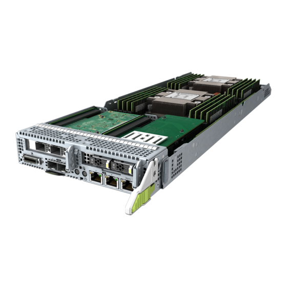
1.3 Logical Structure 1.1 Overview The XH321 V5 is a server node designed for Huawei X6000 servers. An X6000 can house up to four XH321 V5 server nodes in a 2U chassis. The XH321 V5 delivers supreme performance and high storage density in limited space through innovative design. -
Page 10: Physical Structure
FusionServer Pro XH321 V5 Server Node Maintenance and Service Guide 1 Overview Figure 1-1 XH321 V5 1.2 Physical Structure Figure 1-2 XH321 V5 physical structure Issue 07 (2019-12-20) Copyright © Huawei Technologies Co., Ltd. -
Page 11: Logical Structure
The RAID controller card connects to the mainboard using a SAS cable and connects to the system backplane through a connector. ● The BMC chipset interconnects with the PCH through PCIe and LPC buses to provide a management interface. Issue 07 (2019-12-20) Copyright © Huawei Technologies Co., Ltd. - Page 12 The BMC integrates the graphics card, video compression, and virtual media component to provide device management functions, such as power control, slot ID acquisition, power supply detection, and KVM over IP. Issue 07 (2019-12-20) Copyright © Huawei Technologies Co., Ltd.
-
Page 13: Hardware Description
2.4 Storage 2.5 I/O Expansion 2.6 Boards 2.1 Front Panel 2.1.1 Appearance Figure 2-1 Front view PCIe card (RAID controller PCIe cards card not configured) Slide-out label plate (with an SN label) Issue 07 (2019-12-20) Copyright © Huawei Technologies Co., Ltd. -
Page 14: Indicators And Buttons
GE electrical port Connection status Data transmission status indicator for a GE indicator for the electrical port management network port Connection status indicator for the management network port Issue 07 (2019-12-20) Copyright © Huawei Technologies Co., Ltd. - Page 15 ● Blinking red at 1 Hz: A major alarm has been generated on the system. ● Blinking red at 5 Hz: A critical alarm has been generated on the system. ● Steady green: The device is operating properly. Issue 07 (2019-12-20) Copyright © Huawei Technologies Co., Ltd.
- Page 16 ● Blinking yellow: Data is being transmitted. GE electrical port Connection ● Off: The network port is not connected. status ● Steady green: The network port is properly indicator for a connected. GE electrical port Issue 07 (2019-12-20) Copyright © Huawei Technologies Co., Ltd.
-
Page 17: Ports
LOM port 1 (10GE optical port) LOM port 2 (10GE LOM port 3 (GE optical port) electrical port) LOM port 4 (GE Management network electrical port) port ● Ports on the multi-port cable Issue 07 (2019-12-20) Copyright © Huawei Technologies Co., Ltd. - Page 18 2.0 ports, and one RJ45 serial port. Management RJ45 Used for server management. network port NOTE The management network port is a GE port that supports 100 Mbit/s and 1000 Mbit/s auto- negotiation. Issue 07 (2019-12-20) Copyright © Huawei Technologies Co., Ltd.
-
Page 19: Installation Positions
NVMe SSDs are not supported. ● The processor heat sink varies depending on the processor power: – If the maximum processor power is 165 W, use a narrow conjoined heat sink. Issue 07 (2019-12-20) Copyright © Huawei Technologies Co., Ltd. -
Page 20: Memory
If the processor power is higher than 165 W, use a wide conjoined heat sink. ● The same model of processors must be used in a server. ● Contact your local Huawei sales representative or use the Intelligent Computing Compatibility Checker to determine the components to be used. Figure 2-6 Processor positions 2.3 Memory... -
Page 21: Memory Subsystem Architecture
Install memory modules in primary memory channels first. If the primary memory channel is not populated, the memory modules in secondary memory channels cannot be used. Table 2-4 Memory channels Memory Channel Memory Slot CPU 1 1A (primary) DIMM000(A) DIMM001(G) DIMM010(B) Issue 07 (2019-12-20) Copyright © Huawei Technologies Co., Ltd. -
Page 22: Memory Compatibility
Maximum operating speed of a memory module ● The DDR4 memory modules of different types (RDIMM and LRDIMM) and specifications (capacity, bit width, rank, and height) cannot be used together. ● Contact your local Huawei sales representative or use the Intelligent Computing Compatibility Checker to determine the components to be used. - Page 23 Rated speed (MT/s) 2933 Operating voltage (V) Maximum number of DDR4 memory modules in a node Maximum DDR4 memory capacity of the node 1024 (GB) Maximum operating 1DPC 2933 speed (MT/s) 2DPC 2666 Issue 07 (2019-12-20) Copyright © Huawei Technologies Co., Ltd.
-
Page 24: Memory Installation Guidelines
Memory scrubbing mode Comply with the general installation guidelines. 2.3.5 Memory Installation Positions An XH321 V5 supports a maximum of 16 DDR4 memory modules. Balanced memory configuration is recommended for optimal memory performance. Issue 07 (2019-12-20) Copyright © Huawei Technologies Co., Ltd. - Page 25 At least one DDR4 memory module must be installed in the memory slots corresponding to CPU 1. Figure 2-8 Memory slots Figure 2-9 DDR4 memory installation guidelines (1 processor) Figure 2-10 DDR4 memory installation guidelines (2 processors) Issue 07 (2019-12-20) Copyright © Huawei Technologies Co., Ltd.
-
Page 26: Memory Protection Technologies
M.2 SSDs ● a: The M.2 SSDs come in two sizes 2242 and 2280, and support the SATA interface. ● Contact your local Huawei sales representative or use the Intelligent Computing Compatibility Checker to determine the components to be used. -
Page 27: Drive Numbering
2.4.3 RAID Controller Card The RAID controller card supports RAID configuration, RAID level migration, and drive roaming. ● Contact your local Huawei sales representative or use the Intelligent Computing Compatibility Checker to determine the components to be used. Table 2-7 RAID levels supported by the XH321 V5... -
Page 28: I/O Expansion
● N indicates the number of member drives in a RAID array. 2.5 I/O Expansion 2.5.1 PCIe Cards PCIe cards provide ease of expandability and connection. ● Contact your local Huawei sales representative or use the Intelligent Computing Compatibility Checker to determine the components to be used. 2.5.2 PCIe Slots Figure 2-12 PCIe Slot 2.5.3 PCIe Slot Description... -
Page 29: Boards
PCIe card link width. 2.6 Boards 2.6.1 Mainboard Figure 2-13 XH321 V5 mainboard PCIe slot 1 Southbridge RAID controller card Slimline connector connector CPU 1 DIMM050 connector DIMM040 connector DIMM030 connector Issue 07 (2019-12-20) Copyright © Huawei Technologies Co., Ltd. - Page 30 SoftRAID key connector Battery iBMC management LOM GE port 4 network port LOM GE port 3 UID button/indicator Power button/indicator 2 x 10GE optical ports Optical port indicator Universal connector port Issue 07 (2019-12-20) Copyright © Huawei Technologies Co., Ltd.
-
Page 31: Product Specifications
● Min. 1.375 MB L3 cache per core ● Max. 205 W TDP NOTE The preceding information is for reference only. Use the Intelligent Computing Compatibility Checker to obtain specific information. Issue 07 (2019-12-20) Copyright © Huawei Technologies Co., Ltd. - Page 32 (RDIMM and LRDIMM) and specifications (capacity, bit width, rank, and height) cannot be used together. NOTE The preceding information is for reference only. Use the Intelligent Computing Compatibility Checker to obtain specific information. Issue 07 (2019-12-20) Copyright © Huawei Technologies Co., Ltd.
- Page 33 RAID level migration, and drive roaming. – The RAID controller card does not occupy a standard PCIe slot. For details about the RAID controller card, see Huawei V5 Server RAID Controller Card User Guide. Issue 07 (2019-12-20) Copyright © Huawei Technologies Co., Ltd.
- Page 34 For details, see 2.5.2 PCIe Slots 2.5.3 PCIe Slot Description. ● Support Huawei proprietary PCIe SSD cards to bolster I/O performance for applications such as searching, caching, and download services. NOTE The preceding information is for reference only. Use the...
-
Page 35: Environmental Specifications
A.2 Operating Temperature Limitations. Relative humidity (RH, ● Operating humidity: 8% to 90% non-condensing) ● Storage humidity: 5% to 95% ● Long-term storage humidity: 30% to 69% ● Maximum change rate: 20%/h Issue 07 (2019-12-20) Copyright © Huawei Technologies Co., Ltd. -
Page 36: Physical Specifications
● Net weight: 4.2 kg (9.26 lb) configuration ● Packing material weight: 2.73 kg (6.02 lb) Power consumption The power consumption parameters vary with the configuration. Use the Huawei Server Power Calculator to obtain specific information. Issue 07 (2019-12-20) Copyright © Huawei Technologies Co., Ltd. -
Page 37: Software And Hardware Compatibility
NO TICE Do not use incompatible components. Otherwise, the server may fail to work properly. The technical support and warranty do not cover faults caused by incompatible components. Issue 07 (2019-12-20) Copyright © Huawei Technologies Co., Ltd. -
Page 38: Safety Instructions
Take protective measures if a Class A product is used in residential areas as it is likely to cause radio interference. Personal Safety ● Only personnel certified or authorized by Huawei are allowed to install the hardware. ● Stop any operation that may cause personal injury or equipment damage, report the problem to a project supervisor immediately, and take protective measures. - Page 39 Fasten the strap buckle and ensure that the ESD wrist strap is in contact with your skin. Insert the ground terminal attached to the ESD wrist strap into the jack on the grounded rack or chassis. Issue 07 (2019-12-20) Copyright © Huawei Technologies Co., Ltd.
- Page 40 Ensure that the equipment being transported is always upright. Take necessary precautions to prevent collisions, corrosion, package damage, damp conditions and pollution. ● Transport the equipment in its original packaging. Issue 07 (2019-12-20) Copyright © Huawei Technologies Co., Ltd.
- Page 41 General Administration of Quality ● Men: 15/33.08 Supervision, Inspection and Quarantine ● Women: 10/22.05 of the People's Republic of China (AQSIQ) For more information about security instructions, see Huawei Server Safety Information. Issue 07 (2019-12-20) Copyright © Huawei Technologies Co., Ltd.
-
Page 42: Esd
During parts replacement, keep new server components in ESD bags before installation, and place removed server components on ESD mats for temporary storage. ● Do not touch pins, wires, or integrated circuits. Issue 07 (2019-12-20) Copyright © Huawei Technologies Co., Ltd. -
Page 43: Grounding Methods To Prevent Electrostatic Discharge
● Use conductive field service tools. ● Use a portable field service kit with a folding static-dissipating work mat. Issue 07 (2019-12-20) Copyright © Huawei Technologies Co., Ltd. -
Page 44: Internal Cabling
Internal Cabling 7.1 TPM Cabling 7.2 Screw-in RAID Controller Card Cabling 7.3 Cabling of the SATA Controller Integrated in the Southbridge 7.4 PCIe Card Cabling 7.1 TPM Cabling Figure 7-1 TPM cabling Issue 07 (2019-12-20) Copyright © Huawei Technologies Co., Ltd. -
Page 45: Screw-In Raid Controller Card Cabling
Signal cable for connecting the screw-in RAID controller card (Port A) to the Slimline connector 04052070 Signal cable for connecting the screw-in RAID controller card (Port B) to the Slimline connector Issue 07 (2019-12-20) Copyright © Huawei Technologies Co., Ltd. -
Page 46: Cabling Of The Sata Controller Integrated In The Southbridge
Figure 7-3 Internal cabling for the SATA controller integrated in the southbridge Table 7-3 Cabling of the SATA Controller Integrated in the Southbridge Huawei BOM Description Code 04052068 Signal cable for connecting the southbridge to the Slimline connector Issue 07 (2019-12-20) Copyright © Huawei Technologies Co., Ltd. -
Page 47: Pcie Card Cabling
Huawei BOM Description Code 04080606 Signal cable for connecting the PCIe card to the NC-SI connector This cable is required only when the PCIe card is an SP380 NIC (BOM code: 02312JBD). Issue 07 (2019-12-20) Copyright © Huawei Technologies Co., Ltd. -
Page 48: Parts Replacement
Generally, warehouses based safety stock is not on the contract kept for NRSPs. service type. NRSPs are provided on demand; however, the lead time is not committed. Issue 07 (2019-12-20) Copyright © Huawei Technologies Co., Ltd. -
Page 49: Obtaining Tools
ESD bags ● Box cutter ● M3 Phillips screwdriver ● PH1 screwdriver ● Flat-head screwdriver ● Die-casting pliers Used to remove LC optical fibers, pluggable optical modules, and unshielded network cables. Issue 07 (2019-12-20) Copyright © Huawei Technologies Co., Ltd. -
Page 50: Basic Operations
Log in to the iBMC WebUI. For details, see 10.2 Logging In to the iBMC WebUI. Choose Power > Power Control. The Power Control page is displayed. iii. Click Power On. A confirmation message is displayed. Issue 07 (2019-12-20) Copyright © Huawei Technologies Co., Ltd. -
Page 51: Power-Off Procedure
For details, see 2.1.2 Indicators and Buttons. ● Use the iBMC WebUI. Log in to the iBMC WebUI. Issue 07 (2019-12-20) Copyright © Huawei Technologies Co., Ltd. -
Page 52: Removing An Xh321 V5
Press the two tabs on the multi-port cable connector. See (1) in Figure 8-3. Remove the multi-port cable from the universal connector port (UCP) on the server. See (2) in Figure 8-3. Issue 07 (2019-12-20) Copyright © Huawei Technologies Co., Ltd. - Page 53 Use the die-casting pliers to clamp the optical cable connector and remove it from the port. Figure 8-4 Removing optical cables using die-casting pliers Use the die-casting pliers to clamp the optical module, unlock the security pin, and remove the optical module. Issue 07 (2019-12-20) Copyright © Huawei Technologies Co., Ltd.
- Page 54 Holding the ejector lever, pull the server node out of the chassis horizontally. See (3) in Figure 8-6. Close the ejector lever. Figure 8-6 Removing the server node Step 6 Place the removed server node in an ESD bag. Issue 07 (2019-12-20) Copyright © Huawei Technologies Co., Ltd.
-
Page 55: Installing An Xh321 V5
Press the ejector release button on the filler module. See (1) in Figure 8-8. Fully open the ejector lever. See (2) in Figure 8-8. Holding the ejector lever, pull the filler module from the chassis. See (3) in Figure 8-8. Issue 07 (2019-12-20) Copyright © Huawei Technologies Co., Ltd. - Page 56 To prevent device damage or personal injury, hold the bottom of the device with both hands when installing it. Press the ejector release button on the server node. See (1) in Figure 8-9. Fully open the ejector lever. See (2) in Figure 8-9. Issue 07 (2019-12-20) Copyright © Huawei Technologies Co., Ltd.
- Page 57 Slide the server node into the chassis horizontally. See (1) in Figure 8-10. Close the ejector lever. See (2) in Figure 8-10. Figure 8-10 Installing a server node Step 4 Connect the multi-port cable as required. Issue 07 (2019-12-20) Copyright © Huawei Technologies Co., Ltd.
-
Page 58: Field Replaceable Units
Step 6 Power on the server node. For details, see 8.3.1 Power-On Procedure. Step 7 Check indicator status. For details, see 2.1.2 Indicators and Buttons. ----End 8.4 Field Replaceable Units Issue 07 (2019-12-20) Copyright © Huawei Technologies Co., Ltd. -
Page 59: Removing An M.2 Ssd
Use an M2.5 Phillips screwdriver to loosen the screw that secures the M.2 SSD. See (1) in Figure 8-13. Tilt the M.2 SSD 20° to 30° upwards, and pull it out. See (2) in Figure 8-13. Issue 07 (2019-12-20) Copyright © Huawei Technologies Co., Ltd. -
Page 60: Installing An M.2 Ssd
Step 3 Place the server node on the ESD workstation. Step 4 Remove the air duct. For details, see 8.4.23 Removing the Air Duct. Step 5 Determine the position of the M.2 SSD. Issue 07 (2019-12-20) Copyright © Huawei Technologies Co., Ltd. - Page 61 Tilt the M.2 SSD 20° to 30°, install it in the slot, and press it firmly. See (1) in Figure 8-15. Use an M2.5 Phillips screwdriver to tighten the screw to secure the M.2 SSD. See (2) in Figure 8-15. Issue 07 (2019-12-20) Copyright © Huawei Technologies Co., Ltd.
-
Page 62: Removing The Screw-In Raid Controller Card
8.4.3 Removing the Screw-in RAID Controller Card Procedure Step 1 Power off the server node. For details, see 8.3.2 Power-Off Procedure. Step 2 Remove the server node. For details, see 8.3.3 Removing an XH321 Issue 07 (2019-12-20) Copyright © Huawei Technologies Co., Ltd. - Page 63 Step 8 Remove the RAID controller card. Loosen the screws that secure the RAID controller card. See (1) in Figure 8-17. Remove the RAID controller card from the connector on the mainboard. See (2) in Figure 8-17. Issue 07 (2019-12-20) Copyright © Huawei Technologies Co., Ltd.
-
Page 64: Installing The Screw-In Raid Controller Card
If yes, go to Step ● If no, go to Step Step 6 Install the supercapacitor. For details, see 8.4.6 Installing the Supercapacitor. Step 7 Determine the position of the screw-in RAID controller card. Issue 07 (2019-12-20) Copyright © Huawei Technologies Co., Ltd. - Page 65 Tighten the screws to secure the RAID controller card. See (2) in Figure 8-19. Figure 8-19 Installing a screw-in RAID controller card Step 9 Connect the cable to the RAID controller card. For details, see 7 Internal Cabling. Issue 07 (2019-12-20) Copyright © Huawei Technologies Co., Ltd.
-
Page 66: Removing The Supercapacitor
Step 11 Power on the server node. For details, see 8.3.1 Power-On Procedure. Step 12 Configure the RAID controller card. For details, see Huawei V5 Server RAID Controller Card User Guide. ----End 8.4.5 Removing the Supercapacitor Procedure Step 1 Power off the server node. - Page 67 Figure 8-21. Figure 8-21 Removing a TFM Go to Step Step 9 Remove the cable between the supercapacitor and the RAID controller card. Step 10 Remove the supercapacitor from the holder. Issue 07 (2019-12-20) Copyright © Huawei Technologies Co., Ltd.
-
Page 68: Installing The Supercapacitor
Step 5 Determine the position of the supercapacitor. Step 6 Vertically insert the supercapacitor into the holder until the supercapacitor is locked. Figure 8-23 Installing the supercapacitor Step 7 Check whether the supercapacitor is configured with a TFM. Issue 07 (2019-12-20) Copyright © Huawei Technologies Co., Ltd. - Page 69 Figure 8-24 Removing the screw-in RAID controller card Insert the TFM card into the screw-in RAID controller card. See (1) and (2) in Figure 8-25. Tighten the screws to secure the TFM card. See (3) in Figure 8-25. Issue 07 (2019-12-20) Copyright © Huawei Technologies Co., Ltd.
- Page 70 See (1) in Figure 8-26. Install the node panel. See (2) in Figure 8-26. Tighten the screws to secure the panel. See (3) in Figure 8-26. Issue 07 (2019-12-20) Copyright © Huawei Technologies Co., Ltd.
-
Page 71: Removing The Avago Sas3004Imr Pcie Raid Control Card
RAID Controller Card. Step 6 Remove the Avago SAS3004iMR RAID controller card. For details, see 8.4.19 Removing a PCIe Card. Step 7 Place the removed component in an ESD bag. ----End Issue 07 (2019-12-20) Copyright © Huawei Technologies Co., Ltd. -
Page 72: Installing The Avago Sas3004Imr Pcie Raid Control Card
NO TICE Determine the position of the M.2 FRU to be removed. Do not remove the M.2 FRU running an OS. Otherwise, all services on the server node will be affected. Issue 07 (2019-12-20) Copyright © Huawei Technologies Co., Ltd. -
Page 73: Installing An M.2 Fru On The Avago Sas3004Imr Pcie Raid Controller Card
Perform this step only when an M.2 FRU is not installed immediately. ----End 8.4.10 Installing an M.2 FRU on the Avago SAS3004iMR PCIe RAID Controller Card The M.2 FRU on the Avago SAS3004iMR RAID controller card is hot swappable. Issue 07 (2019-12-20) Copyright © Huawei Technologies Co., Ltd. - Page 74 Close the handle of the M.2 FRU. See (2) in Figure 8-30. Figure 8-30 Installing an M.2 FRU Step 4 Check the status of the M.2 FRU indicator on the Avago SAS3004iMR RAID controller card. Issue 07 (2019-12-20) Copyright © Huawei Technologies Co., Ltd.
-
Page 75: Removing A Processor
----End 8.4.11 Removing a Processor NO TICE ● Only Huawei technical support or personnel authorized by Huawei can remove the processors from Huawei servers. ● Do not wear ESD gloves during processor replacement. The gloves may catch on pins on the processor socket and damage it. - Page 76 Insert only the tip of the flat-head screwdriver. Do not apply excessive force. Holding the other end of the carrier, remove the carrier and processor in the arrow direction. See (4) and (5) in Figure 8-33. Issue 07 (2019-12-20) Copyright © Huawei Technologies Co., Ltd.
- Page 77 Bend the edge of the carrier with the triangular hole to release the processor from the carrier. Figure 8-34 Removing a processor (1) Hold the two sides of the processor and lift it. Issue 07 (2019-12-20) Copyright © Huawei Technologies Co., Ltd.
- Page 78 Aligning the processor socket cover with the guide pin on the processor socket, place the cover on the processor socket. See (1) in Figure 8-36. Press the positions shown by (2) in Figure 8-36 until you hear a click. Issue 07 (2019-12-20) Copyright © Huawei Technologies Co., Ltd.
-
Page 79: Installing A Processor
----End 8.4.12 Installing a Processor NO TICE ● Only Huawei technical support or personnel authorized by Huawei can install the processors from Huawei servers. ● Do not wear ESD gloves during processor replacement. The gloves may catch on pins on the processor socket and damage it. - Page 80 Aligning the notch in one edge of the processor with the protrusion on the processor carrier, secure it. Ensure that the processor corner with a triangle mark is in the corner of the processor carrier with a notched triangle. Issue 07 (2019-12-20) Copyright © Huawei Technologies Co., Ltd.
- Page 81 0.4 ml of thermal compound on the area. – When applying thermal compound, place the processor carrier on the desktop. – The thermal compound injector has volume marks. The two-line, five-dot, s-shape, and X-shape patterns are recommended. Issue 07 (2019-12-20) Copyright © Huawei Technologies Co., Ltd.
- Page 82 Step 9 Install the processor carrier to the conjoined heat sink. Aligning the processor corner with a triangle mark with the corner of the heat sink with a notched triangle, buckle the processor carrier on the heat sink. Issue 07 (2019-12-20) Copyright © Huawei Technologies Co., Ltd.
- Page 83 Shine a light at various angles onto the processor socket to check for twisted pins, foreign matter, and pad damage. NO TICE If bent pins or foreign matters are found or the bonding pad is damaged, stop the operation and contact Huawei technical support. Issue 07 (2019-12-20) Copyright © Huawei Technologies Co., Ltd.
- Page 84 8.4.24 Installing the Air Duct. Step 12 Install the server node. For details, see 8.3.4 Installing an XH321 Step 13 Power on the server node. For details, see 8.3.1 Power-On Procedure. ----End Issue 07 (2019-12-20) Copyright © Huawei Technologies Co., Ltd.
-
Page 85: Removing A Memory Module
Step 6 Remove the memory module. Open the memory module ejectors on the memory slot. See (1) in Figure 8-45. Remove the memory module from the slot. See (2) in Figure 8-45. Issue 07 (2019-12-20) Copyright © Huawei Technologies Co., Ltd. -
Page 86: Installing A Memory Module
If the processor power is 200 W or 205 W, a wide conjoined heat sink is required, which occupy memory channels DIMM001 and DIMM031. Procedure Step 1 Power off the server node. For details, see 8.3.2 Power-Off Procedure. Issue 07 (2019-12-20) Copyright © Huawei Technologies Co., Ltd. - Page 87 The two memory ejectors are closed automatically after the memory module is firmly seated. Do not touch the edge connector on a memory module with bare hands. Before installing a memory module, ensure that the edge connector is not contaminated. Issue 07 (2019-12-20) Copyright © Huawei Technologies Co., Ltd.
- Page 88 – If information about the original memory module is displayed, access the BIOS and check memory information. For details, see Huawei Server Purley Platform BIOS Parameter Reference. ----End Issue 07 (2019-12-20) Copyright © Huawei Technologies Co., Ltd.
-
Page 89: Removing The Tpm
● If the TPM function has been set on the BIOS, record the settings before removing the TPM. After replacing the TPM, configure the related settings on the BIOS again. Huawei Server Purley Platform BIOS Parameter For details, see the Reference ●... - Page 90 See (1) in Figure 8-50. Remove the TPM from the dowel pins on the side wall of the server node and take it out upwards. See (2) in Figure 8-50. Issue 07 (2019-12-20) Copyright © Huawei Technologies Co., Ltd.
-
Page 91: Installing The Tpm
Step 3 Place the server node on the ESD workstation. Step 4 Remove the air duct. For details, see 8.4.23 Removing the Air Duct. Step 5 Determine the position of the TPM. Issue 07 (2019-12-20) Copyright © Huawei Technologies Co., Ltd. - Page 92 8.4.2 Installing an M.2 SSD. Step 9 Install the TPM. Align the TPM with the dowel pins on the side wall of the server node, and insert the TPM in the arrow direction. Issue 07 (2019-12-20) Copyright © Huawei Technologies Co., Ltd.
- Page 93 For details, see 8.3.1 Power-On Procedure. Step 14 Enable TPM. Access the BIOS interface. For details, see Huawei Server Purley Platform BIOS Parameter Reference. Select Security. Select TPM Operation and press Enter. Select Enable. Press F10. The system displays "Exit Saving changes?" dialog box is displayed.
-
Page 94: Removing The Battery
For details, see 8.4.19 Removing a PCIe Card. Step 6 Press and hold the two latches outwards until the battery ejects, and remove the battery vertically. See (1) and (2) in Figure 8-54. Issue 07 (2019-12-20) Copyright © Huawei Technologies Co., Ltd. -
Page 95: Installing The Battery
Step 3 Place the server node on the ESD workstation. Step 4 Take the spare part out of its ESD bag. Step 5 Determine the position of the battery. Figure 8-55 Position of the battery Issue 07 (2019-12-20) Copyright © Huawei Technologies Co., Ltd. -
Page 96: Removing A Pcie Card
Step 2 Remove the server node. For details, see 8.3.3 Removing an XH321 Step 3 Place the server node on the ESD workstation. Step 4 Determine the position of the PCIe card. Issue 07 (2019-12-20) Copyright © Huawei Technologies Co., Ltd. -
Page 97: Installing A Pcie Card
Step 7 Place the removed component in an ESD bag. ----End 8.4.20 Installing a PCIe Card Procedure Step 1 Power off the server node. For details, see 8.3.2 Power-Off Procedure. Step 2 Remove the server node. Issue 07 (2019-12-20) Copyright © Huawei Technologies Co., Ltd. - Page 98 Step 7 Install the PCIe riser modules. For details, see 8.4.22 Installing the PCIe Riser Module. Step 8 Install the server node. For details, see 8.3.4 Installing an XH321 Step 9 Power on the server node. Issue 07 (2019-12-20) Copyright © Huawei Technologies Co., Ltd.
-
Page 99: Removing The Pcie Riser Module
Lift the PCIe riser module in the arrow direction. See (4) in Figure 8-61. Figure 8-61 Removing the PCIe riser module Step 6 Disconnect the cable between the PCIe card and the NC-SI port. For details, see 7.4 PCIe Card Cabling. Issue 07 (2019-12-20) Copyright © Huawei Technologies Co., Ltd. - Page 100 Step 8 Place the removed PCIe riser module and PCIe card in different ESD bags. Step 9 Install a filler panel. Perform this operation only when a PCIe riser module is not installed immediately. Issue 07 (2019-12-20) Copyright © Huawei Technologies Co., Ltd.
-
Page 101: Installing The Pcie Riser Module
Maintenance and Service Guide 8 Parts Replacement Figure 8-62 Installing a filler panel ----End 8.4.22 Installing the PCIe Riser Module Procedure Step 1 Power off the server node. For details, see 8.3.2 Power-Off Procedure. Issue 07 (2019-12-20) Copyright © Huawei Technologies Co., Ltd. - Page 102 Step 3 Place the server node on the ESD workstation. Step 4 Determine the position of the PCIe riser module. Step 5 Remove the filler panel. Perform this operation only when a filler panel is installed. Issue 07 (2019-12-20) Copyright © Huawei Technologies Co., Ltd.
- Page 103 Step 7 Install the PCIe card. For details, see 8.4.20 Installing a PCIe Card. Step 8 Connect the cable between the PCIe card and the NC-SI port. For details, see 7.4 PCIe Card Cabling. Issue 07 (2019-12-20) Copyright © Huawei Technologies Co., Ltd.
-
Page 104: Removing The Air Duct
Step 11 Power on the server node. For details, see 8.3.1 Power-On Procedure. ----End 8.4.23 Removing the Air Duct Procedure Step 1 Power off the server node. For details, see 8.3.2 Power-Off Procedure. Issue 07 (2019-12-20) Copyright © Huawei Technologies Co., Ltd. -
Page 105: Installing The Air Duct
8.3.3 Removing an XH321 Step 3 Place the server node on the ESD workstation. Step 4 Take the spare part out of its ESD bag. Step 5 Determine the position of the air duct. Issue 07 (2019-12-20) Copyright © Huawei Technologies Co., Ltd. -
Page 106: Removing The Mainboard And Server Node Case
Step 2 Check the iBMC and BIOS configurations. Step 3 Export the iBMC or BIOS configuration files. For details, see iBMC WebUI > Configuration > Import/Export in FusionServer Pro X6000 Server iBMC User Guide. Issue 07 (2019-12-20) Copyright © Huawei Technologies Co., Ltd. - Page 107 Step 8 Determine the position of the mainboard and the server node case. Figure 8-67 Mainboard and server node case The mainboard is packed in the server node case and replaced as a whole package. Issue 07 (2019-12-20) Copyright © Huawei Technologies Co., Ltd.
-
Page 108: Installing The Mainboard And Server Node Case
Step 1 Take the spare part out of its ESD bag. Step 2 Place the server node on the ESD workstation. Step 3 Determine the position of the mainboard and the server node case. Issue 07 (2019-12-20) Copyright © Huawei Technologies Co., Ltd. - Page 109 8.4.24 Installing the Air Duct. Step 12 Install the server node. For details, see 8.3.4 Installing an XH321 Step 13 Power on the server node. For details, see 8.3.1 Power-On Procedure. Issue 07 (2019-12-20) Copyright © Huawei Technologies Co., Ltd.
- Page 110 Step 18 Upgrade the iBMC, BIOS, and CPLD to the versions used before the replacement (recommended) or to the latest versions. For details, see FusionServer Pro High-Density Server Upgrade Guide. ----End Issue 07 (2019-12-20) Copyright © Huawei Technologies Co., Ltd.
-
Page 111: Troubleshooting
If a fault occurs on a server, collect logs for fault diagnosis. ● Fault diagnosis Fault diagnosis rules and tools help Huawei technical support engineers and maintenance engineers to analyze and rectify faults according to alarms and hardware fault symptoms. -
Page 112: Common Operations
Step 2 Choose Advanced > IPMI iBMC Configuration, and press Enter. The IPMI iBMC Configuration screen is displayed. Step 3 Select iBMC Configuration and press Enter. The iBMC Configuration screen is displayed. Issue 07 (2019-12-20) Copyright © Huawei Technologies Co., Ltd. -
Page 113: Logging In To The Ibmc Webui
Windows 8 64-bit JRE 1.8 U45 JRE 1.8 U144 Mozilla Firefox 39.0 to 54.0 Google Chrome 21.0 to 44.0 Windows 10 64-bit Internet Explorer 11.0 JRE 1.8 U45 JRE 1.8 U144 Issue 07 (2019-12-20) Copyright © Huawei Technologies Co., Ltd. - Page 114 PC to communicate with the iBMC. //IP address of the iBMC management network Step 4 Open Internet Explorer, enter https: port in the address box, and press Enter. The iBMC login page is displayed. Issue 07 (2019-12-20) Copyright © Huawei Technologies Co., Ltd.
- Page 115 If Domain is not This iBMC, the maximum length of the user name is 255 characters. Select This iBMC or Automatic matching from the Domain drop-down list. Click Log In. Issue 07 (2019-12-20) Copyright © Huawei Technologies Co., Ltd.
- Page 116 Domain drop-down list. Click Log In. After the login is successful, the Information page is displayed. The user name is displayed in the upper right corner. ----End Issue 07 (2019-12-20) Copyright © Huawei Technologies Co., Ltd.
-
Page 117: Logging In To The Desktop Of A Server
Step 1 Log in to the iBMC WebUI. For details, see 10.2 Logging In to the iBMC WebUI. Step 2 On the menu bar, choose Remote Console. Figure 10-2 Remote Console page Issue 07 (2019-12-20) Copyright © Huawei Technologies Co., Ltd. - Page 118 Each user can view the operations performed by the other user. ● HTML5 supports only Internet Explorer 10.0 and later versions. Figure 10-3 Remote console (Java) Issue 07 (2019-12-20) Copyright © Huawei Technologies Co., Ltd.
-
Page 119: Using The Independent Remote Console
● Windows 7 32-bit or 64-bit ● Windows 8 32-bit or 64-bit ● Windows 10 32-bit or 64-bit ● Windows Server 2008 R2 32-bit or 64-bit ● Windows Server 2012 64-bit Issue 07 (2019-12-20) Copyright © Huawei Technologies Co., Ltd. - Page 120 Each user can view the operations performed by the other user. ● Private Mode: allows only one user to access and manage a server at a time. Step 5 Click Connect. A security warning is displayed. Issue 07 (2019-12-20) Copyright © Huawei Technologies Co., Ltd.
-
Page 121: Ubuntu
The server desktop is displayed. Figure 10-7 Server desktop ----End 10.3.2.2 Ubuntu The following Ubuntu versions are supported: ● Ubuntu 14.04 LTS ● Ubuntu 16.04 LTS Issue 07 (2019-12-20) Copyright © Huawei Technologies Co., Ltd. - Page 122 Each user can view the operations performed by the other user. ● Private Mode: allows only one user to access and manage a server at a time. Step 7 Click Connect. A security warning is displayed. Issue 07 (2019-12-20) Copyright © Huawei Technologies Co., Ltd.
-
Page 123: Macos
The server desktop is displayed. Figure 10-10 Server desktop ----End 10.3.2.3 macOS The following macOS version is supported: ● Mac OS X El Capitan Issue 07 (2019-12-20) Copyright © Huawei Technologies Co., Ltd. - Page 124 Each user can view the operations performed by the other user. ● Private Mode: allows only one user to access and manage a server at a time. Step 7 Click Connect. A security warning is displayed. Issue 07 (2019-12-20) Copyright © Huawei Technologies Co., Ltd.
-
Page 125: Logging In To The Cli
● Click Import CA to import the CA certificate (*.cer, *.crt, or *.pem). After the CA certificate is imported, the security risk dialog box will no longer be displayed. The server desktop is displayed. Figure 10-13 Server desktop ----End 10.4 Logging In to the CLI Issue 07 (2019-12-20) Copyright © Huawei Technologies Co., Ltd. -
Page 126: Logging In To The Cli Using Putty Over A Network Port
191.100.34.32. ● Port: Retain the default value 22. ● Connection type: Retain the default value SSH. Step 5 In the navigation tree, choose Session. Step 6 Select SSH under Connection type. Issue 07 (2019-12-20) Copyright © Huawei Technologies Co., Ltd. - Page 127 ● If an incorrect user name or password is entered, you must set up a new PuTTY session. Step 9 Enter the user name and password. If the login is successful, the server host name is displayed on the left of the prompt. ----End Issue 07 (2019-12-20) Copyright © Huawei Technologies Co., Ltd.
-
Page 128: Logging In To The Cli Using Putty Over A Serial Port
Flow control: None n in COM n indicates a serial port number, and its value is an integer. Step 4 In the navigation tree, choose Session. Step 5 Select Serial under Connection type. Issue 07 (2019-12-20) Copyright © Huawei Technologies Co., Ltd. -
Page 129: Accessing The Bios
Click Yes to proceed. Step 8 Enter the user name and password. If the login is successful, the server host name is displayed on the left of the prompt. ----End 10.5 Accessing the BIOS Issue 07 (2019-12-20) Copyright © Huawei Technologies Co., Ltd. -
Page 130: Accessing The Bios (Skylake)
● To boot from the network, press F12. Enter the password in the displayed dialog box. ● To access the Smart Provisioning GUI, press F6. The screen for entering the BIOS password is displayed. Issue 07 (2019-12-20) Copyright © Huawei Technologies Co., Ltd. -
Page 131: Accessing The Bios (Cascade Lake)
Step 2 On the Remote Virtual Console, click on the menu bar. Step 3 Select Reset or Forced System Reset. "Are you sure to perform this operation?" is displayed. Step 4 Click Yes. Issue 07 (2019-12-20) Copyright © Huawei Technologies Co., Ltd. - Page 132 ● To go to the Boot Manager screen, press F11 pr F3. ● To boot from the network, press F12. ● To access the Smart Provisioning GUI, press F6. The screen for entering the BIOS password is displayed. Issue 07 (2019-12-20) Copyright © Huawei Technologies Co., Ltd.
- Page 133 ● The system will be locked if an incorrect password is entered three consecutive times. You can restart the server node to unlock it. The Setup Utility program is started. Step 7 Select BIOS Configuration by pressing arrow keys. The Main screen is displayed. ----End Issue 07 (2019-12-20) Copyright © Huawei Technologies Co., Ltd.
-
Page 134: More Information
11 More Information More Information 11.1 Technical Support 11.2 Product Information 11.3 Product Configuration Resources 11.4 Maintenance Tools 11.1 Technical Support Huawei provides timely and efficient technical support through: ● Local branch offices ● Secondary technical support system ● Telephone technical support ●... -
Page 135: Product Information
– Send emails to support@huawei.com. Telecom carriers outside China: visit Global TAC Information. ● Contact the technical support personnel of your local Huawei office. 11.2 Product Information Table 11-1 provides common information about Huawei servers. Table 11-1 Product information Item... -
Page 136: Product Configuration Resources
CPU quantity, and DIMM quantity are specified. 11.4 Maintenance Tools Table 11-3 lists the software tools required for routine maintenance of Huawei servers. Table 11-3 Software tools for routine maintenance Tool Server Model Description... - Page 137 Tools 2.0 servers. SmartKit User Download link: FusionServer Tools Guide. Smart For details, see Smart Provisioning installs OSs, configures Provisioning Smart RAID, and upgrades firmware. Provisioning Download link: Smart Provisioning User Guide. Issue 07 (2019-12-20) Copyright © Huawei Technologies Co., Ltd.
-
Page 138: Software And Configuration Utilities
12.2 BIOS 12.3 FusionServer Tools SmartKit 12.1 iBMC Huawei intelligent Baseboard Management Controller (iBMC) is a Huawei proprietary intelligent system for remotely managing a server. The iBMC complies with IPMI 2.0 and SNMP standards and supports various functions, including KVM redirection, text console redirection, remote virtual media, and hardware monitoring and management. -
Page 139: Bios
I/O and boot device, and finally boots the OS. The BIOS also provides the advanced configuration and power interface (ACPI) and hot swap. The Huawei Purley-based server is developed based on Insyde code base and uses a proprietary BIOS. It provides a variety of in-band and out-of-band configuration functions as well as high scalability, and supports customization. -
Page 140: Fusionserver Tools Smartkit
Configure BMC IP addresses for servers in batches. configuration Health check Perform health check for servers in batches. Visualized health reports are provided, helping users to learn about the server running status in real time. Issue 07 (2019-12-20) Copyright © Huawei Technologies Co., Ltd. - Page 141 Parse iBMC logs to analyze and locate faults. E9000 switch module Perform analysis of switch module logs. The log analysis configuration information and status of switch modules are displayed in graphics, helping locate network problems. Issue 07 (2019-12-20) Copyright © Huawei Technologies Co., Ltd.
- Page 142 SmartKit allows only read operations during health check and log collection and does not collect customers' service information. After a health check or log collection is complete, the log collection script and files will be automatically deleted. Issue 07 (2019-12-20) Copyright © Huawei Technologies Co., Ltd.
-
Page 143: A Appendix
A Appendix Appendix A.1 Product SN The serial number (SN) on the slide-out label plate uniquely identifies a device. The SN is required when you contact Huawei technical support. Figure A-1 SN example Table A-1 SN description Callout No. Description SN ID (two characters), which is 21. -
Page 144: Operating Temperature Limitations
Internal model, that is, product name. A.2 Operating Temperature Limitations For configurations not listed in the table, the operating temperature range is 5°C (41°F) to 30°C (86°F). For special configuration and temperature requirements, contact Huawei technical support. A.2.1 Operating Temperature Limitations (Supercapacitor for... - Page 145 140 W ≤ P ≤ 165 W 32°C (89.6°F) P < 140 W 35°C (95°F) 0 < Q ≤ 4 165 W < P ≤ 205 W 32°C (89.6°F) P ≤ 165 W 35°C (95°F) Issue 07 (2019-12-20) Copyright © Huawei Technologies Co., Ltd.
-
Page 146: Operating Temperature Limitations (Optical Modules Configured)
35°C (95°F) X6000 V5 C10 16 < Q ≤ 24 165 W < P ≤ 24 NVMe 205 W backplane 140 W < P ≤ 30°C (86°F) 30°C (86°F) 165 W Issue 07 (2019-12-20) Copyright © Huawei Technologies Co., Ltd. - Page 147 P ≤ 140 W 35°C (95°F) 35°C (95°F) 0 < Q ≤ 8 165 W < P ≤ 35°C (95°F) 30°C (86°F) 205 W P ≤ 165 W 35°C (95°F) 35°C (95°F) Issue 07 (2019-12-20) Copyright © Huawei Technologies Co., Ltd.
-
Page 148: Operating Temperature Limitations (Avago Sas3004Imr Raid Controller Card + M.2 Fru Configured)
140 W < P ≤ 165 W 30°C (86°F) P ≤ 140 W 35°C (95°F) 0 < Q ≤ 8 140 W < P ≤ 165 W 35°C (95°F) P ≤ 140 W 35°C (95°F) Issue 07 (2019-12-20) Copyright © Huawei Technologies Co., Ltd. - Page 149 4 < Q ≤ 8 165 W < P ≤ 205 W 30°C (86°F) 140 W < P ≤ 165 W 35°C (95°F) 0 < Q ≤ 4 P ≤ 205 W 35°C (95°F) Issue 07 (2019-12-20) Copyright © Huawei Technologies Co., Ltd.
-
Page 150: Operating Temperature Limitations (Different Models Of Processors)
Intel® Xeon® Wide ● 8 < drives 30°C (86°F) 24 x 2.5" SAS 3100, 4100, conjoined ≤ 16 backplane 5100, 6100 heat sinks ● Memory and 8100 modules ≤ series processors Issue 07 (2019-12-20) Copyright © Huawei Technologies Co., Ltd. -
Page 151: Ras Features
The server supports a variety of Reliability, Availability, and Serviceability (RAS) features. You can configure these features for better RAS. For details about how to configure RAS features, see Huawei Server Purley Platform BIOS Parameter Reference. Issue 07 (2019-12-20) Copyright © Huawei Technologies Co., Ltd. - Page 152 Protection via CRC (CRC) protection for UPI packets to improve system reliability. System Core Disable for Fault Isolates a faulty CPU core during Resilient Boot (FRB) startup to improve system reliability and availability. Issue 07 (2019-12-20) Copyright © Huawei Technologies Co., Ltd.
- Page 153 BIOS-based Predictive The BIOS provides physical unit Failure Analysis (PFA) information for DIMM errors, and the OS traces and predicts errors, and isolates error memory pages. Issue 07 (2019-12-20) Copyright © Huawei Technologies Co., Ltd.
-
Page 154: B Glossary
Intel and DEC. Ethernet uses the Carrier Sense Multiple Access/Collision Detection (CSMA/CD) access method and allows data transfer over various cables at 10 Mbit/s. The Ethernet specification is the basis for the IEEE 802.3 standard. Issue 07 (2019-12-20) Copyright © Huawei Technologies Co., Ltd. -
Page 155: F-J
An external component (including but not limited to ejector levers, indicators, and ports) on the front or rear of the server. It seals the front and rear of the chassis to ensure optimal ventilation and electromagnetic compatibility (EMC). Issue 07 (2019-12-20) Copyright © Huawei Technologies Co., Ltd. -
Page 156: U-Z
A unit defined in International Electrotechnical Commission (IEC) 60297-1 to measure the height of a cabinet or chassis. 1 U = 44.45 mm UltraPath A point-to-point processor interconnect developed by Interconnect (UPI) Intel. Issue 07 (2019-12-20) Copyright © Huawei Technologies Co., Ltd. -
Page 157: C Acronyms And Abbreviations
Advanced Encryption Standard New Instruction Set Address Resolution Protocol Advanced Vector Extensions backup battery unit BIOS Basic Input/Output System baseboard management controller calendar day Conformite Europeenne Common Information Model command-line interface Issue 07 (2019-12-20) Copyright © Huawei Technologies Co., Ltd. -
Page 158: F-J
Execute Disable Bit European Efficiency enterprise resource planning European Telecommunication Standards C.2 F-J FB-DIMM Fully Buffered DIMM Fiber Channel Federal Communications Commission FCoE Fibre Channel over Ethernet File Transfer Protocol Gigabit Ethernet Issue 07 (2019-12-20) Copyright © Huawei Technologies Co., Ltd. -
Page 159: K-O
IGMP Internet Group Message Protocol IOPS input/output operations per second Internet Protocol intelligent power capability IPMB Intelligent Platform Management Bus IPMI Intelligent Platform Management Interface C.3 K-O keyboard, video, and mouse Issue 07 (2019-12-20) Copyright © Huawei Technologies Co., Ltd. -
Page 160: P-T
NC-SI Network Controller Sideband Interface C.4 P-T PCIe Peripheral Component Interconnect Express power distribution unit physical layer PMBUS power management bus power OK pulse-width modulation Preboot Execution Environment Quick Path Interconnect Issue 07 (2019-12-20) Copyright © Huawei Technologies Co., Ltd. - Page 161 LAN SONCAP Standards Organization of Nigeria-Conformity Assessment Program solid-state drive Streaming SIMD Extensions TACH tachometer signal Turbo Boost Technology Trusted Computing Group trusted cryptography module total cost of ownership Issue 07 (2019-12-20) Copyright © Huawei Technologies Co., Ltd.
-
Page 162: U-Z
Universal Serial Bus VCCI Voluntary Control Council for Interference by Information Technology Equipment Video Graphics Array VLAN virtual local area network voltage regulator-down WEEE waste electrical and electronic equipment WSMAN Web Service Management Issue 07 (2019-12-20) Copyright © Huawei Technologies Co., Ltd.
Need help?
Do you have a question about the FusionServer Pro XH321 V5 V100R005 and is the answer not in the manual?
Questions and answers