
Related Manuals for Huawei 5288 V3 V100R003


Summary of Contents for Huawei 5288 V3 V100R003
- Page 1 5288 V3 Server V100R003 User Guide Issue Date 2018-11-19 HUAWEI TECHNOLOGIES CO., LTD.
- Page 2 Notice The purchased products, services and features are stipulated by the contract made between Huawei and the customer. All or part of the products, services and features described in this document may not be within the purchase scope or the usage scope. Unless otherwise specified in the contract, all statements, information, and recommendations in this document are provided "AS IS"...
-
Page 3: About This Document
Indicates a potentially hazardous situation which, if not avoided, could result in equipment damage, data loss, performance deterioration, or unanticipated results. NOTICE is used to address practices not related to personal injury. Issue 26 (2018-11-19) Copyright © Huawei Technologies Co., Ltd. - Page 4 For details, see 7.33 Removing the Supercapacitor (RAID Controller Card), 7.34 Removing the Supercapacitor (Standard RAID Controller Card), 7.35 Installing the Supercapacitor (RAID Controller Card), 7.36 Installing the Supercapacitor (Standard RAID Controller Card). Issue 26 (2018-11-19) Copyright © Huawei Technologies Co., Ltd.
- Page 5 PCIe SSDs. For details, see 7.8 Installing an NVMe PCIe SSD. 2017-01-24 Added operations for replacing the front bezel. For details, see 7.3 (Optional) Removing the Front Bezel 7.4 (Optional) Installing the Front Bezel. Issue 26 (2018-11-19) Copyright © Huawei Technologies Co., Ltd.
- Page 6 Card. 2015-12-21 Modified the mainboard layout description. For details, see 2.6 Mainboard Layout. 2015-12-16 Added product specifications. For details, see 2.11 Product Specifications. 2015-07-15 This issue is the first official release. Issue 26 (2018-11-19) Copyright © Huawei Technologies Co., Ltd.
-
Page 7: Table Of Contents
3.5.1 Connecting Cables to a Mouse, Keyboard, and VGA Port..................69 3.5.2 Connecting a Network Cable.............................70 3.5.3 Connecting a Cable to a 10GE Port...........................72 3.5.4 Connecting a USB Device............................75 3.5.5 Connecting a Serial Cable............................76 Issue 26 (2018-11-19) Copyright © Huawei Technologies Co., Ltd. - Page 8 7.9.2 Removing a DC PSU............................... 132 7.10 Installing a PSU................................ 134 7.10.1 Installing an AC PSU............................134 7.10.2 Installing a DC PSU.............................. 136 7.11 Removing the Chassis Cover............................138 7.12 Installing the Chassis Cover............................. 139 Issue 26 (2018-11-19) Copyright © Huawei Technologies Co., Ltd.
- Page 9 7.45 Removing a SATADOM............................210 7.46 Installing a SATADOM.............................211 7.47 Removing an SD Card.............................. 213 7.48 Installing an SD Card............................... 216 7.49 Removing an SD Card Board........................... 219 7.50 Installing an SD Card Board.............................220 Issue 26 (2018-11-19) Copyright © Huawei Technologies Co., Ltd. viii...
- Page 10 10.1 Collecting Fault Information............................ 278 10.2 Preparing for Debugging............................278 10.3 Using Product Documentation..........................279 10.4 Obtaining Technical Support............................ 279 11 Appendix........................... 280 11.1 Glossary..................................280 11.2 Acronyms and Abbreviations........................... 281 11.3 Sensor List................................284 Issue 26 (2018-11-19) Copyright © Huawei Technologies Co., Ltd.
-
Page 11: Safety Instructions
Personal Safety Ensure that only personnel authorized by Huawei install hardware. In case of any problems that may cause injury to personnel or damage to devices, immediately stop operations and report the problems to a project supervisor and take corrective measures. - Page 12 High-voltage power supply provides power for device operation. Do not touch high- voltage cables directly or through conductive materials. This may cause danger of electrocution. Issue 26 (2018-11-19) Copyright © Huawei Technologies Co., Ltd.
- Page 13 Use only genuine components that can be queried in the Huawei Server Compatibility Checker. Only maintenance engineers authorized by Huawei are allowed to expand capacity. Avoid physical damage caused by electrostatic discharge, collision, and scratches. Before expanding capacity, back up data and isolate the equipment from the network to prevent data loss, service interruption, and network loops.
- Page 14 National Institute for Occupational Safety and Health (NIOSH) 23/50.72 Health and Safety Executive (HSE) 25/55.13 General Administration of Quality Supervision, Inspection and l Male: 15/33.01 Quarantine of the People's Republic of China (AQSIQ) l Female: 10/22.05 Issue 26 (2018-11-19) Copyright © Huawei Technologies Co., Ltd.
-
Page 15: Product Overview
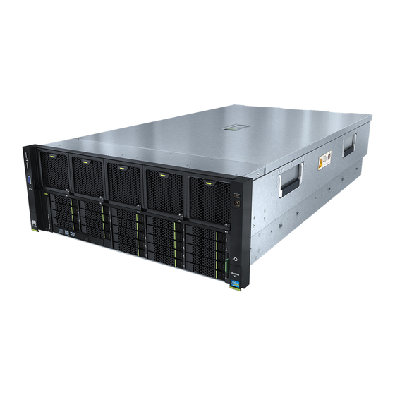
2.12 Technical Specifications 2.1 Overview The 5288 V3 server (marked as H52M-03 on the nameplate, 5288 V3 for short) is the Huawei new-generation 4 U dual-socket or single-socket rack server that adopts effective design to ensure excellent computing performance and large-capacity local storage with elastic scalability. - Page 16 HDDs, and SSDs. l (Optional) Four built-in 3.5-inch or 2.5-inch SAS HDDs, SATA HDDs, or SSDs NOTE The slots for NVMe PCIe SSDs also support 2.5–inch SAS HDDs, SATA HDDs, or SSDs. Issue 26 (2018-11-19) Copyright © Huawei Technologies Co., Ltd.
-
Page 17: Appearance
2 Product Overview Figure 2-1 5288 V3 2.2 Appearance Front Panel Figure 2-2 shows the 5288 V3 front panel. Figure 2-2 5288 V3 front panel Network port link status indicators USB 2.0 port Issue 26 (2018-11-19) Copyright © Huawei Technologies Co., Ltd. - Page 18 Serial port VGA port Connectivity status indicator Management network port (Mgmt) Data transmission status USB 3.0 port indicator UID indicator PCIe slot LAN on motherboard (flexible Rear hard disk flexible NIC) Issue 26 (2018-11-19) Copyright © Huawei Technologies Co., Ltd.
- Page 19 PSU indicator PSU 1 NVMe PCIe SSD yellow indicator NVMe PCIe SSD green indicator PSU 2 NVMe PCIe SSDs (numbered 32 to 35 from left to right and from top to bottom) Issue 26 (2018-11-19) Copyright © Huawei Technologies Co., Ltd.
- Page 20 Checker. The following figures show flexible NIC ports and indicators. Figure 2-5 SM211 ports and indicators Data transmission status Connection status indicator indicator Figure 2-6 SM210 or SM212 ports and indicators Issue 26 (2018-11-19) Copyright © Huawei Technologies Co., Ltd.
- Page 21 Figure 2-8 SM231 ports and indicators Data transmission status Connection status indicator indicator PCIe Slot Layout Figure 2-9 shows the PCIe slot layout of the 5288 V3. Figure 2-9 PCIe slot layout Issue 26 (2018-11-19) Copyright © Huawei Technologies Co., Ltd.
- Page 22 80/02/ 82/00/0 Full-height slot PCIe full-length PCIe riser riser modu ule: l 3-slot l 3- PCIe slot riser PCIe modu riser le: x8 ule: Slot PCIe Port 80/02/ 83/00/0 Full-height half-length Issue 26 (2018-11-19) Copyright © Huawei Technologies Co., Ltd.
- Page 23 Huawei Server Compatibility Checker. For PCIe cards out of the Huawei Server Compatibility Checker, contact your local Huawei sales personnel. Note 6: Table 2-2 lists the default values of B/D/F. If CPUs are not in full configuration or a PCIe card with a PCI bridge is configured, the values of B/D/F may differ.
-
Page 24: Ports
A 3-slot riser module does not support any GPU. ESNs An Equipment Serial Number (ESN) is a string that uniquely identifies a server. An ESN is required when you apply for technical support to Huawei. Figure 2-10 shows the ESN format by using the example 2102310QPD10F3001263. - Page 25 The serial port is used as the system serial port by default. You can set it as the iBMC serial port by using the iBMC command. The port is used for debugging. Issue 26 (2018-11-19) Copyright © Huawei Technologies Co., Ltd.
-
Page 26: Indicators And Buttons
When the server is powered on, you can hold down this button for 6 seconds to power off the server. l When the server is ready to be powered on, you can press this button to start the server. Issue 26 (2018-11-19) Copyright © Huawei Technologies Co., Ltd. - Page 27 Off: The port is not in use or faulty. l Steady green: The port is properly connected. NOTE If the flexible NIC provides two network ports, they correspond to network port indicators 1 and 2 on the front panel. Issue 26 (2018-11-19) Copyright © Huawei Technologies Co., Ltd.
- Page 28 For details about command description, see HUAWEI V2&V3 Server RAID Controller Card User Guide. Table 2-7 describes the NVMe PCIe SSD indicators on the 5288 V3 rear panel. Issue 26 (2018-11-19) Copyright © Huawei Technologies Co., Ltd.
- Page 29 Is Execut Being such Trans as eth0 mitted on the eth1.) Netwo SM211 i350 Active Yellow No data flexible transmi with tted on two GE electric networ al ports Issue 26 (2018-11-19) Copyright © Huawei Technologies Co., Ltd.
- Page 30 Link Green networ connect ion. Steady networ connect ion is normal. SM212 i350 Active Yellow No data flexible transmi with tted on four networ electric al ports Issue 26 (2018-11-19) Copyright © Huawei Technologies Co., Ltd.
- Page 31 Link Green networ connect ion. Steady networ connect ion is normal. SM231 82599 Active Yellow Steady No data flexible transmi with tted on 10GE networ optical ports Issue 26 (2018-11-19) Copyright © Huawei Technologies Co., Ltd.
- Page 32 Blinkin 2.0 Hz connect ion is normal. SM233 X540 Link Green Steady High flexible Speed rate (10 Gb/s) with Yellow Steady rate 10GE electric b/s) al ports networ connect ion. Issue 26 (2018-11-19) Copyright © Huawei Technologies Co., Ltd.
-
Page 33: Physical Structure
Data is 2.5 Hz 2.0 Hz Active being transmi tted on networ Steady No data transmi tted on networ networ connect ion. 2.5 Physical Structure Figure 2-11 shows the 5288 V3 components. Issue 26 (2018-11-19) Copyright © Huawei Technologies Co., Ltd. - Page 34 RAID controller card DIMM Heat sink Mainboard PSU backplane SATA disk on module Hard disk (SATADOM) Right mounting ear Left mounting ear Rear hard disk backplane for Chassis 12 disks Supercapacitor Supercapacitor tray Issue 26 (2018-11-19) Copyright © Huawei Technologies Co., Ltd.
- Page 35 To query the flexible NICs supported by the 5288 V3, use the Huawei Server Compatibility Checker. PCIe card Two half-height half-length PCIe 3.0 x8 slots for standard PCIe cards on the mainboard Issue 26 (2018-11-19) Copyright © Huawei Technologies Co., Ltd.
- Page 36 RAID 1 array when being detected. You can view the information about the SD cards and RAID 1 array on the iBMC WebUI by choosing System Info > Other, but cannot modify the configuration or manually configure them. Issue 26 (2018-11-19) Copyright © Huawei Technologies Co., Ltd.
- Page 37 Capacity per DIMM: 8 GB, 16 GB, 32 GB, 64 GB, or 128 GB. l Memory speed: DDR4 1866 MT/s, 2133 MT/s, or 2400 MT/s Heat sink Dissipates heat from a CPU. Each CPU is configured with one heat sink. Issue 26 (2018-11-19) Copyright © Huawei Technologies Co., Ltd.
- Page 38 1920 pixels x 1200 pixels while other OSs only support the maximum resolution supported by the built-in drivers. l If the resolution is greater than 1024 x 768, the display effect may be affected. Connects PSUs to the mainboard. backplane Issue 26 (2018-11-19) Copyright © Huawei Technologies Co., Ltd.
- Page 39 Protects RAID cache data from power failures for RAID controller itor card using LSI SAS3108 or PM8060 chips on the 5288 V3. Supercapac Secures a supercapacitor for a RAID controller card. itor tray Issue 26 (2018-11-19) Copyright © Huawei Technologies Co., Ltd.
-
Page 40: Mainboard Layout
Front hard Supplies power to front hard disks and provides data transmission disk channels. backplane 2.6 Mainboard Layout Figure 2-12 show the ports on the 5288 V3 mainboard. Issue 26 (2018-11-19) Copyright © Huawei Technologies Co., Ltd. - Page 41 PCIe x8 slot 5 (corresponding to CPU 1, PCIe x8 slot 4 (corresponding to J49 PCIe x8 slot HH/HL) CPU 1, J50 PCIe x8 slot HH/HL) I/O flexible NIC connector (J46-J45) PCH Mini-SAS HD connector (J1001) Issue 26 (2018-11-19) Copyright © Huawei Technologies Co., Ltd.
-
Page 42: Internal Cabling
Storage Signal Cabling The ports on an RAID controller card may look different from the picture in this topic, depending on the card model. Signal cables to the front hard disk backplane Issue 26 (2018-11-19) Copyright © Huawei Technologies Co., Ltd. - Page 43 Signal cable for connecting the front hard disk 04051053 backplane (J35) to the rear hard disk backplane marked 8 (J24) Signal cable for connecting the front hard disk 04051340 backplane (J1 MAIN BOARD) to the mainboard (J1003) Issue 26 (2018-11-19) Copyright © Huawei Technologies Co., Ltd.
- Page 44 PCIe slot using SAS cables when the 5288 V3 is equipped with dual RAID controller cards. This topic assumes that a standard RAID controller card is installed in a PCIe x8 slot on the mainboard. Issue 26 (2018-11-19) Copyright © Huawei Technologies Co., Ltd.
- Page 45 Signal cable for connecting the rear 12-bay hard disk 04051053 backplane (J1) to the front hard disk backplane (J36) Storage Power Cabling Power cables to the front hard disk backplane and the rear 2-bay hard disk backplane Issue 26 (2018-11-19) Copyright © Huawei Technologies Co., Ltd.
- Page 46 CONN3) Power cable for connecting the front hard disk 04151498 backplane (J61 POWER) to the PSU backplane (J4) Power cable for connecting the rear 12-bay hard disk backplane to the mainboard Issue 26 (2018-11-19) Copyright © Huawei Technologies Co., Ltd.
- Page 47 Front Mounting Ear Cabling Cables for connecting the front mounting ears on the left and right of the 5288 V3 to the mainboard Figure 2-18 Cables to the front mounting ears Issue 26 (2018-11-19) Copyright © Huawei Technologies Co., Ltd.
- Page 48 Figure 2-19 Internal cabling for an M.2 SSD riser card Description BOM Number SATA cable for connecting the SATA1 port of an M. 04051409 2 SSD riser card to the mainboard (J37) Issue 26 (2018-11-19) Copyright © Huawei Technologies Co., Ltd.
- Page 49 12-bay hard disk contact backplane (Port 3- Huawei Port 3) technical support. SAS cable for 04051282 connecting an NVMe PCIe SSD adapter to the rear 12-bay hard disk backplane (Port 2- Port 2) Issue 26 (2018-11-19) Copyright © Huawei Technologies Co., Ltd.
-
Page 50: Logical Structure
E5-2600 v3 series CPUs or two Intel Xeon E5-2600 v4 series CPUs. For details about the CPU positions, see 2.6 Mainboard Layout. The server in single-CPU configuration does not support a PCIe riser card. Issue 26 (2018-11-19) Copyright © Huawei Technologies Co., Ltd. -
Page 51: Ras Features
Failed DIMM isolation Identifies a faulty dual in-line memory module (DIMM), and isolates it from others before replacing the DIMM. Memory thermal Automatically adjusts DIMM temperatures to avoid throttling damage due to overheating. Issue 26 (2018-11-19) Copyright © Huawei Technologies Co., Ltd. - Page 52 OS over the APEI of the Advanced Configuration and Power Interface (ACPI), and locates the error unit, improving system availability. Error injection support Injects errors to verify various RAS features. Issue 26 (2018-11-19) Copyright © Huawei Technologies Co., Ltd.
-
Page 53: Software And Hardware Compatibility
For SLES 12.0, an NVMe PCIe SSD cannot be used as a boot device. Windows Windows Server For Windows Server 2012, the NVMe 2012 PCIe SSD driver must be manually installed. Windows Windows Server 2012 R2 Issue 26 (2018-11-19) Copyright © Huawei Technologies Co., Ltd. -
Page 54: Product Specifications
You are advised to upgrade the iBMC and BIOS to the latest mapping versions. l The CPUs on one server must have the same BOM number. For details about BOM numbers, see Huawei Server Compatibility Checker. Chipset Intel C612 Issue 26 (2018-11-19) Copyright © Huawei Technologies Co., Ltd. - Page 55 – Supports a supercapacitor for power failure protection. These RAID controller cards support RAID level migration and drive roaming. NOTE The SP435 (PM8060) controller card is a standard PCIe card, which can be installed in a PCIe slot. Issue 26 (2018-11-19) Copyright © Huawei Technologies Co., Ltd.
- Page 56 Preboot Execution Environment (PXE) l Four GE optical ports, supporting NC-SI, WOL, and PXE l Two 10GE optical ports, supporting NC-SI and PXE l Two 10GE electrical ports, supporting NC-SI, WOL, and PXE Issue 26 (2018-11-19) Copyright © Huawei Technologies Co., Ltd.
- Page 57 – Two half-height half-length standard PCIe 3.0 x8 slots on the mainboard (PCIe slot signals come from CPU 1.) l PCIe slots on an I/O module can house a maximum of two Huawei ES3000 V2 SSDs to improve I/O performance for search, cache, and download services.
-
Page 58: Technical Specifications
– Provides the GUI, virtual KVM, virtual media, Serial Over LAN (SOL), intelligent power supply, remote control, and hardware monitoring features. l NC-SI l Supports Huawei eSight management software and integration with third-party management systems, such as VMware vCenter, Microsoft SystemCenter, and Nagios. Security... - Page 59 Depth: > 1000 mm (39.37 in.) Guide rail installation requirements are as follows: l L-shaped guide rails: apply only to a Huawei cabinet. l Adjustable guide rails: apply to a cabinet where the distance between the front and rear mounting bars is 543.5 mm to 848.5 mm (21.40 in.
- Page 60 30°C. l The 5288 V3 supports the maximum operating temperature of 35°C (95°F) when it is equipped with rear hard disks, 135 W CPUs, or Huawei PCIe SSDs. l The operating performance of hard disks may deteriorate when a single fan module fails.
- Page 61 There is no explosive, conductive, magnetic, or corrosive dust in the equipment room. Power The power consumption changes depending on the server consumption configuration. For details, see Huawei Server Power Calculator. Issue 26 (2018-11-19) Copyright © Huawei Technologies Co., Ltd.
-
Page 62: Installing And Removing The 5288 V3
1U or more can be reserved between servers. Installation Process Understand the entire installation process before installing the 5288 V3. Figure 3-1 shows the process for installing the 5288 V3. Issue 26 (2018-11-19) Copyright © Huawei Technologies Co., Ltd. -
Page 63: Installation Environment
The server draws in cool air from the front of the cabinet and exhausts hot air from the rear. Therefore, the front and rear of the cabinet must be well ventilated for optimal heat dissipation. Figure 3-2 shows the direction of heat dissipation. Issue 26 (2018-11-19) Copyright © Huawei Technologies Co., Ltd. -
Page 64: Temperature And Humidity Requirements
When installing the server, the cabinet must meet the following requirements: A standard 19-inch cabinet with a depth of more than 1000 mm (39.37 in.). Complies with International Electrotechnical Commission 297 (IEC 297). Issue 26 (2018-11-19) Copyright © Huawei Technologies Co., Ltd. -
Page 65: Unpacking The Chassis
This topic describes how to install a server on L-shaped guide rails, adjustable guide rails, and holding rails. Choose an installation method based on site conditions. Install a server if: Additional servers are required in a cabinet for capacity expansion. Issue 26 (2018-11-19) Copyright © Huawei Technologies Co., Ltd. -
Page 66: Installing The Server On L-Shaped Guide Rails
Screwdriver: used to tighten screws on the panel Floating nut hook: used to install floating nuts 3.4.1 Installing the Server on L-Shaped Guide Rails L-shaped guide rails apply only to a Huawei cabinet. Procedure Step 1 Determine the positions for installing floating nuts. See Figure 3-3. - Page 67 Step 3 Install L-shaped guide rails. Place a guide rail horizontally in the designated position and keep the guide rail in contact with the mounting bars in the cabinet. See Figure 3-6. Issue 26 (2018-11-19) Copyright © Huawei Technologies Co., Ltd.
- Page 68 Lift the 5288 V3 and move it to the cabinet. This task requires at least four people. Place the 5288 V3 onto the guide rails and slide it into the cabinet. See step (1) in Figure 3-7. Issue 26 (2018-11-19) Copyright © Huawei Technologies Co., Ltd.
-
Page 69: Installing The Server On Adjustable Guide Rails
Three types of dowel pins are shipped with the guide rails, and their diameters are 6.8 mm (0.27 in.), 8.7 mm (0.34 in.), and 9.2 mm (0.36 in.). Choose dowel pins with the largest diameter that can pass through the holes. Issue 26 (2018-11-19) Copyright © Huawei Technologies Co., Ltd. - Page 70 Guide rails are divided into left and right guide rails (labeled with L and R). A pair of guide rails should be installed together and cannot be installed reversely. Figure 3-9 Installing an adjustable guide rail Issue 26 (2018-11-19) Copyright © Huawei Technologies Co., Ltd.
-
Page 71: Installing The Server On Holding Rails
609 mm (23.98 in.) to 914 mm (35.98 in.). When installing the RH5288 V3 on the holding rails, you can configure a cable management arm (CMA) to arrange the external cables connected to the server. Issue 26 (2018-11-19) Copyright © Huawei Technologies Co., Ltd. - Page 72 Pull out an inner rail from a holding rail until the inner rail cannot move, push the release button upward, and remove the inner rail from the holding rail. See steps (1) and (2) in Figure 3-12. Issue 26 (2018-11-19) Copyright © Huawei Technologies Co., Ltd.
- Page 73 Align the screws on the server with the notches in the inner guide rails, push the server forward until you hear a sound, and ensure that the latches eject and completely block the screws to fix the server to the inner guide rails. See Figure 3-13. Issue 26 (2018-11-19) Copyright © Huawei Technologies Co., Ltd.
- Page 74 Check that the buckles on the support trays are properly secured and the support trays touch the fixing blocks of the middle rails. See Figure 3-14. If the support trays are not in such a position, manually adjust them. Otherwise, the rolling balls may fall. Issue 26 (2018-11-19) Copyright © Huawei Technologies Co., Ltd.
- Page 75 Lift the server, align the inner rails with the holding rails, and push the server into the cabinet. See Figure 3-15. NOTE At least four persons are required to lift the server. Issue 26 (2018-11-19) Copyright © Huawei Technologies Co., Ltd.
- Page 76 Figure 3-16 Clipping the inner rail into the middle rail Press the release buttons on both sides, and push the server into the cabinet until the server cannot move forward. See Figure 3-17. Issue 26 (2018-11-19) Copyright © Huawei Technologies Co., Ltd.
- Page 77 3 Installing and Removing the 5288 V3 Figure 3-17 Pushing a server into a cabinet Tighten the captive screws on the mounting ears to secure the server. See Figure 3-18. Figure 3-18 Securing a server Issue 26 (2018-11-19) Copyright © Huawei Technologies Co., Ltd.
- Page 78 Slot the right inner arm of the CMA between the protrusions of the right inner rail. See step (3) in Figure 3-19. Step 5 (Optional) If a CMA is installed, the external cables connected to the server must be routed into the CMA. See Figure 3-20. Issue 26 (2018-11-19) Copyright © Huawei Technologies Co., Ltd.
-
Page 79: Connecting External Cables
Connect a keyboard and mouse by using a USB-to-PS/2 cable. Procedure Step 1 Connect the USB connector on the PS/2 cable to the USB port on the front or rear panel of the server. Issue 26 (2018-11-19) Copyright © Huawei Technologies Co., Ltd. -
Page 80: Connecting A Network Cable
Before installing a network cable to a network port, check that the network cable connector is intact and the pins have no sundries or deformation. The following tools are available: Phillips screwdriver: used to tighten screws Issue 26 (2018-11-19) Copyright © Huawei Technologies Co., Ltd. - Page 81 Step 5 Connect the new network cable. Note the following: Connect the new network cable to the same port as the removed one. Install the network cable in the network port securely. Issue 26 (2018-11-19) Copyright © Huawei Technologies Co., Ltd.
-
Page 82: Connecting A Cable To A 10Ge Port
ESD wrist strap or ESD gloves: used to prevent ESD damage Procedure Step 1 Check the new network model. Step 2 Number the new cable. The new cable must have the same number as the old one. Issue 26 (2018-11-19) Copyright © Huawei Technologies Co., Ltd. - Page 83 Connect the new optical cable to the same port as the old one. l Connect the optical cable to the optical module securely. Insert the optical module into the optical port. See step (1) in Figure 3-23. Figure 3-23 Connecting an optical cable Issue 26 (2018-11-19) Copyright © Huawei Technologies Co., Ltd.
- Page 84 Remove the dust-proof cap on the port, and insert the cable connector into the port. See Figure 3-25. NOTE When you hear a "click" and the cable cannot be pulled out, the connector is secured. Issue 26 (2018-11-19) Copyright © Huawei Technologies Co., Ltd.
-
Page 85: Connecting A Usb Device
Step 1 Locate the server to which the USB device is to be connected. Step 2 Connect the USB storage device to the USB port on the server, as shown in Figure 3-26. Issue 26 (2018-11-19) Copyright © Huawei Technologies Co., Ltd. -
Page 86: Connecting A Serial Cable
ESD wrist strap or ESD gloves: used to prevent ESD damage Procedure Step 1 Align the connector on the serial cable with the serial port, and insert the connector into the serial port, as shown in Figure 3-27. Issue 26 (2018-11-19) Copyright © Huawei Technologies Co., Ltd. -
Page 87: Connecting A Power Cable
PSU handle after connecting the power cable to the PSU to prevent power cable poor contact or disconnection. See Figure1 Connecting a power cable (secured with the PSU using a velcro strap). Issue 26 (2018-11-19) Copyright © Huawei Technologies Co., Ltd. - Page 88 Select a jack on the power socket for connection. Step 4 Bind the power cable to the cable trough using cable ties. ----End Issue 26 (2018-11-19) Copyright © Huawei Technologies Co., Ltd.
-
Page 89: Laying Out Cables
Lay out and bind cables of different types of cables (such as power and signal cables) separately. Ensure that the distance between power cables and signal cables is longer than or equal to 30 mm (1.18 in.) when you lay out the cables in parallel. Issue 26 (2018-11-19) Copyright © Huawei Technologies Co., Ltd. -
Page 90: Verifying Cable Connections
To ensure optimal heat dissipation, do not block the air exhaust vents of PSUs. 3.5.8 Verifying Cable Connections Before verifying cable connections, ensure that the power is off. Any incorrect or loose connection may cause personal injury or equipment damage. Issue 26 (2018-11-19) Copyright © Huawei Technologies Co., Ltd. -
Page 91: Removing The Server
Step 4 Remove the server. Loosen the captive screws on the 5288 V3 panel using a screwdriver. See step (1) in Figure 1 Removing a serverFigure 3-31. Figure 3-31 Removing the server Issue 26 (2018-11-19) Copyright © Huawei Technologies Co., Ltd. -
Page 92: Removing A Server And Adjustable Guide Rail
Remove power cables first to prevent damage or injury caused by static electricity. Step 4 Remove the server. Loosen the captive screws on the server panel using a screwdriver. See (1) in Figure 3-33. Issue 26 (2018-11-19) Copyright © Huawei Technologies Co., Ltd. - Page 93 Step 6 Shorten the guide rail and take it out. See (2) in Figure 3-34. Figure 3-34 Removing an adjustable guide rail Step 7 Remove the other guide rail on the opposite side in the same way. ----End Issue 26 (2018-11-19) Copyright © Huawei Technologies Co., Ltd.
-
Page 94: Removing The Server And Holding Rails
Pull out the server along the guide rails away from the cabinet as far as the server will go. See (2) in Figure 3-35. Pull the release button upwards, and pull the server out. See (1) and (2) in Figure 3-36. Issue 26 (2018-11-19) Copyright © Huawei Technologies Co., Ltd. - Page 95 Figure 3-36 Removing a server from holding rails Place the removed server onto an ESD platform. Pull the release button outwards, and remove the inner rail. See (1) and (2) in Figure 3-37. Issue 26 (2018-11-19) Copyright © Huawei Technologies Co., Ltd.
- Page 96 Step 5 Remove the front end of the holding rail. Hold down the plate on the front end of the holding rail and pull out the hook. See (1) and (2) in Figure 3-38. Issue 26 (2018-11-19) Copyright © Huawei Technologies Co., Ltd.
- Page 97 Push the plate into the holding rail. See (5) in Figure 3-38. Remove the rear end of the holding rail. Lift the positioning pin and remove the holding rail from the square holes. See (6) and (7) in Figure 3-38. Issue 26 (2018-11-19) Copyright © Huawei Technologies Co., Ltd.
- Page 98 5288 V3 Server User Guide 3 Installing and Removing the 5288 V3 Step 6 Remove the other guide rail on the opposite side in the same way. ----End Issue 26 (2018-11-19) Copyright © Huawei Technologies Co., Ltd.
-
Page 99: Powering On And Off The Server
PSUs. To change the value of Power Strategy, log in to the iBMC WebUI and choose Power > Power Control. If PSUs are powered on and the server is in the standby state, power on the server as follows: Issue 26 (2018-11-19) Copyright © Huawei Technologies Co., Ltd. - Page 100 Figure 4-1 Power Control page Click Power On. In the displayed dialog box, click Yes to power on the server. Verification Check the indicator status after the server is powered on. Issue 26 (2018-11-19) Copyright © Huawei Technologies Co., Ltd.
-
Page 101: Powering Off The Server
After powering off the server, wait at least 1 minute to ensure that the server is completely powered off. Then, you can power on the server again. Procedure Power off the server using the iBMC WebUI. Issue 26 (2018-11-19) Copyright © Huawei Technologies Co., Ltd. - Page 102 The Power Control page is displayed, as shown in Figure 4-2. Figure 4-2 Power Control page Click Power Off. In the displayed dialog box, click Yes to power off the server. Issue 26 (2018-11-19) Copyright © Huawei Technologies Co., Ltd.
-
Page 103: Configuring The 5288 V3
IP address: 192.168.2.100 network port mask of the l Subnet mask: 255.255.255.0 information management network port iBMC management User name and l User name: root system login password l Password: Huawei12#$ information Issue 26 (2018-11-19) Copyright © Huawei Technologies Co., Ltd. -
Page 104: Configuration Process
OS. 5.2 Configuration Process Figure 5-1 shows the process for configuring the server. Figure 5-1 Process for configuring the server Issue 26 (2018-11-19) Copyright © Huawei Technologies Co., Ltd. -
Page 105: Checking The 5288 V3
IP address: 192.168.2.100 network port mask of the l Subnet mask: 255.255.255.0 information management network port iBMC management User name and l User name: root system login password l Password: Huawei12#$ information Issue 26 (2018-11-19) Copyright © Huawei Technologies Co., Ltd. - Page 106 OS. Workflow Check the 5288 V3 by following the sequence described in Figure 5-2. Determine the check method based on site requirements. Figure 5-2 Process for checking the 5288 V3 Issue 26 (2018-11-19) Copyright © Huawei Technologies Co., Ltd.
- Page 107 View the 5288 V3 health status and alarms. Choose Information > Information Summary, and view server health status, as shown in Figure 5-4. Figure 5-4 Querying the health status for the 5288 V3 Issue 26 (2018-11-19) Copyright © Huawei Technologies Co., Ltd.
- Page 108 ----------------Raid Card INFO ------------------- SR130 BoardID: 0x002C SR130 PCB: -------------- HDD Backplane INFO -------------- BC11THBK BoardID: 0x00cb BC11THBK PCB: BC11THBK CPLD Version: (U1011)1.05 BC11THBJ BoardID: 0x00ca BC11THBJ PCB: BC11THBJ CPLD Version: (U3)1.05 Issue 26 (2018-11-19) Copyright © Huawei Technologies Co., Ltd.
-
Page 109: Configuring Raid
Choose Information on the menu bar and choose Component Info or System Info in the navigation tree. The Component Info or System Info page is displayed. View the RAID controller card information, as shown in Figure 5-5 Figure 5-6. Issue 26 (2018-11-19) Copyright © Huawei Technologies Co., Ltd. -
Page 110: Configuring The Bios
Configure the BIOS of the 5288 V3, including setting the server boot mode, selecting PXE as a boot option, enabling the PXE function for a network port, and setting the BIOS password Issue 26 (2018-11-19) Copyright © Huawei Technologies Co., Ltd. - Page 111 For details about how to log in to the remote virtual console, see 9.7 Logging In to the Remote Virtual Console. Select Reset. The system displays "Are you sure to perform this operation?" Issue 26 (2018-11-19) Copyright © Huawei Technologies Co., Ltd.
- Page 112 Press F11 or F3 to go the boot manager screen for selecting boot options. l Press F12 to boot from the network. Figure 5-8 BIOS startup screen Enter a BIOS password when prompted. The screen for setting the BIOS is displayed. Issue 26 (2018-11-19) Copyright © Huawei Technologies Co., Ltd.
- Page 113 The Boot Type Order screen is displayed. NOTE The default boot sequence is as follows: Hard Disk Drive, CD/DVD-ROM Drive, PXE, and finally Others. Figure 5-9 Boot Type Order Select PXE as a boot option. Issue 26 (2018-11-19) Copyright © Huawei Technologies Co., Ltd.
- Page 114 12. Choose Enabled from the shortcut menu and press Enter to enable the PXE function for the network port. Set the BIOS password. 13. Select the Security tab. The Security screen is displayed, as shown in Figure 5-11. Issue 26 (2018-11-19) Copyright © Huawei Technologies Co., Ltd.
- Page 115 After the supervisor password is set, the following menu items are displayed: Clear Supervisor Password Power on Password 15. To change the language, select the Main tab to go to the Main screen, as shown in Figure 5-12. Issue 26 (2018-11-19) Copyright © Huawei Technologies Co., Ltd.
- Page 116 16. Select Language and press Enter. The screen for selecting a language is displayed, as shown in Figure 5-13. Figure 5-13 Selecting a language 17. Select English and press Enter. The GUI language is changed to English, as shown in Figure 5-14. Issue 26 (2018-11-19) Copyright © Huawei Technologies Co., Ltd.
-
Page 117: Changing An Ibmc User Password
Password: operations. Huawei12#$ Procedure Step 1 Log in to the iBMC WebUI over a network port. For details, see 9.2 Logging In to the iBMC WebUI. Issue 26 (2018-11-19) Copyright © Huawei Technologies Co., Ltd. -
Page 118: Setting The Management Network Port Ip Address
Set the management network IP address through the iBMC WebUI, BIOS, and LCD of the iBMC. You can also set the IP address by running the ipaddr command on the iBMC CLI of the iBMC. For details, see HUAWEI Rack Server iBMC User Guide. Issue 26 (2018-11-19) Copyright © Huawei Technologies Co., Ltd. - Page 119 The Network Settings page is displayed. Set an IP address for the management network port, as shown in Figure 5-16. Figure 5-16 Setting an IP address for the management network port Issue 26 (2018-11-19) Copyright © Huawei Technologies Co., Ltd.
- Page 120 The IPMI iBMC Configuration screen is displayed. Select iBMC Configuration and press Enter. The iBMC Configuration screen is displayed, showing information about the IP address of the iBMC network port. See Figure 5-18. Issue 26 (2018-11-19) Copyright © Huawei Technologies Co., Ltd.
- Page 121 Select IP Address in IPV4 configuration and press Enter. On the configuration screen, set the IPv4 address of the iBMC management network port, as shown in Figure 5-19. Figure 5-19 Setting the IPv4 address of the iBMC management network port Issue 26 (2018-11-19) Copyright © Huawei Technologies Co., Ltd.
-
Page 122: Installing An Os
Before configuring the boot from iSCSI function, load the optional ROM for iSCSI. For details, see "Upgrading the Intel X540 flexible NIC Firmware" in the HUAWEI Server Firmware Upgrade Guide. Issue 26 (2018-11-19) Copyright © Huawei Technologies Co., Ltd. -
Page 123: Software And Configuration Utility
(ACPI) and hot swap. The BIOS is stored in the serial peripheral interface (SPI) flash memory. The 5288 V3 server offers a Huawei's proprietary, patented BIOS that uses the Intel Grantley platform and is developed based on the Insyde code base. The BIOS is customizable and scalable, and provides a variety of in-band and out-of-band configuration functions. -
Page 124: Ibmc
HUAWEI Server Grantley Platform BIOS Parameter Reference. 6.2 iBMC The Intelligent Baseboard Management Controller (iBMC) is a Huawei's proprietary system that remotely manages servers. iBMC complies with Intelligent Platform Management Interface (IPMI) 2.0 and Simple Network Management Protocol (SNMP) standards and supports various functions, including keyboard, video, and mouse (KVM) redirection, text console redirection, remote virtual media, and hardware monitoring and management. - Page 125 Guide l iBMC management software: 5288 V3- l FusionServer Tools V100R002 uMate iBMC-V191.zip User Guide l BIOS firmware: 5288 V3-BIOS- l HUAWEI Rack Server Upgrade Guide V169.zip (iBMC) l Driver: FusionServer iDriver-Windows- l Driver Version Mapping Driver-V304.zip Download path: Support >...
- Page 126 HUAWEI Server Firmware Upgrade Guide. Upgrade the BIOS, CPLD, and iBMC using the FusionServer Tools uMate. Log in to http://e.huawei.com/en/, choose Support > Server > Server Management Software > FusionServer Tools, and download the uMate package of the latest version.
- Page 127 The driver upgrade procedure varies according to the OS type and version. For details, see HUAWEI Server OS Installation Guide. Supported OSs To query the OS versions supported by the server, use the Huawei Server Compatibility Checker. Issue 26 (2018-11-19) Copyright © Huawei Technologies Co., Ltd.
-
Page 128: Replacing Parts
7.5 Removing a Hard Disk 7.6 Installing a Hard Disk 7.7 Removing an NVMe PCIe SSD 7.8 Installing an NVMe PCIe SSD 7.9 Removing a PSU 7.10 Installing a PSU 7.11 Removing the Chassis Cover Issue 26 (2018-11-19) Copyright © Huawei Technologies Co., Ltd. - Page 129 7.37 Removing a CPU 7.38 Installing a CPU 7.39 Removing a DIMM 7.40 Installing a DIMM 7.41 Removing the Mainboard 7.42 Installing the Mainboard 7.43 Removing the flexible NIC 7.44 Installing the flexible NIC Issue 26 (2018-11-19) Copyright © Huawei Technologies Co., Ltd.
-
Page 130: Replaceable Parts
Fan module Peripheral Component Interconnect Express (PCIe) card Riser card USB device System battery RAID controller card Supercapacitor Dual in-line memory module (DIMM) Mainboard Flexible NIC SATADOM Secure digital (SD) card Issue 26 (2018-11-19) Copyright © Huawei Technologies Co., Ltd. -
Page 131: Tool Preparations
Step 1 Wear an ESD wrist strap. For details, see 1 Safety Instructions. Step 2 Unlock the front bezel by turning the key clockwise, and remove the key for proper storage. Figure 7-1. Issue 26 (2018-11-19) Copyright © Huawei Technologies Co., Ltd. - Page 132 User Guide 7 Replacing Parts Figure 7-1 Unlocking the front bezel Step 3 Press the button and remove the front bezel. See Figure 7-2. Figure 7-2 Removing the front bezel ----End Issue 26 (2018-11-19) Copyright © Huawei Technologies Co., Ltd.
-
Page 133: Optional) Installing The Front Bezel
Step 2 Remove the key from the front bezel. See Figure 7-3. Figure 7-3 Removing a key Step 3 Unlock the front bezel by turning the key clockwise, and remove the key for proper storage. Figure 7-4. Issue 26 (2018-11-19) Copyright © Huawei Technologies Co., Ltd. - Page 134 Step 4 Hook the front bezel onto the side of the left mounting ear, and press the button so that the front bezel is secured to the chassis. See Figure 7-5. Issue 26 (2018-11-19) Copyright © Huawei Technologies Co., Ltd.
- Page 135 User Guide 7 Replacing Parts Figure 7-5 Installing the front bezel Step 5 Lock the front bezel by turning the key counterclockwise, and remove the key for proper storage. See Figure 7-6. Issue 26 (2018-11-19) Copyright © Huawei Technologies Co., Ltd.
-
Page 136: Removing A Hard Disk
If a hard disk is frequently removed and installed in an interval shorter than 30 seconds, there are risks that the hard disk cannot be identified. Figure 7-7, Figure 7-9, or Figure 7-8 shows the silkscreens of the hard disks on the 5288 V3. Issue 26 (2018-11-19) Copyright © Huawei Technologies Co., Ltd. - Page 137 Figure 7-8 Rear hard disks (one RAID controller card) Figure 7-9 Rear hard disks (two RAID controller cards) Table 7-1 shows the mapping between the silkscreens of the hard disks and slot IDs in the System Event Log. Issue 26 (2018-11-19) Copyright © Huawei Technologies Co., Ltd.
- Page 138 7.3 (Optional) Removing the Front Bezel. Step 4 Determine the position of the hard disk (for example, a front hard disk) on the 5288 V3. See Figure 7-10. Figure 7-10 Hard disk position Issue 26 (2018-11-19) Copyright © Huawei Technologies Co., Ltd.
-
Page 139: Installing A Hard Disk
Step 3 Take the spare hard disk out of its ESD bag. Step 4 Fully raise the ejector lever and push the hard disk into the chassis along the guide rails until it does not move. See step (1) in Figure 7-12. Issue 26 (2018-11-19) Copyright © Huawei Technologies Co., Ltd. -
Page 140: Removing An Nvme Pcie Ssd
(Optional) Installing the Front Bezel. Step 7 After verifying hard disk status, configure RAID properties based on actual service requirements. For details, see the HUAWEI V2&V3 Server RAID Controller Card User Guide. ----End 7.7 Removing an NVMe PCIe SSD For details, see "Removing an ES3000 V3" in the ES3000 V3 NVMe PCIe SSD User Guide. - Page 141 PSU socket. See b of step (1) in Figure2 Removing a power cable (secured with the PSU using a plastic clip). Figure 7-14 Removing a power cable (secured with the PSU using a plastic clip) Issue 26 (2018-11-19) Copyright © Huawei Technologies Co., Ltd.
-
Page 142: Removing A Dc Psu
Observe the PSU indicators to check the PSU operating status. For details about the indicators, see 2.4 Indicators and Buttons. Procedure Step 1 Wear an ESD wrist strap. For details, see 1 Safety Instructions. Issue 26 (2018-11-19) Copyright © Huawei Technologies Co., Ltd. - Page 143 Figure 7-16 Removing power cables Step 4 Hold down the latch on the PSU, and pull out part of the PSU by holding the handle. See step (1) in Figure 7-17. Issue 26 (2018-11-19) Copyright © Huawei Technologies Co., Ltd.
-
Page 144: Installing A Psu
Step 4 Push the spare AC PSU along the guide rails into a slot until the PSU clicks into place. The PSU latch snaps in so that the PSU does not move. See Figure 7-18. Issue 26 (2018-11-19) Copyright © Huawei Technologies Co., Ltd. - Page 145 See Figure2 Connecting a power cable (secured with the PSU using a velcro strap). Figure 7-19 Connecting a power cable (secured with the PSU using a velcro strap) Issue 26 (2018-11-19) Copyright © Huawei Technologies Co., Ltd.
-
Page 146: Installing A Dc Psu
Step 4 Push the spare DC PSU along the guide rails into a slot (for example, slot 1) until you hear a sound. The PSU latch snaps in so that the PSU does not move. See Figure 7-21. Issue 26 (2018-11-19) Copyright © Huawei Technologies Co., Ltd. - Page 147 Connect the OT terminal on the positive power cable to the RTN(+) wiring terminal on the PSU. Connect the OT terminal on the ground cable to the ground terminal on the PSU. Issue 26 (2018-11-19) Copyright © Huawei Technologies Co., Ltd.
-
Page 148: Removing The Chassis Cover
Step 5 Remove the 5288 V3 and put it on an ESD desktop. For details, see 3.6 Removing the Server. Step 6 Loosen the latch that secures the handle of the chassis cover using a flat-head screwdriver. See step (1) in Figure 7-23. Issue 26 (2018-11-19) Copyright © Huawei Technologies Co., Ltd. -
Page 149: Installing The Chassis Cover
Step 2 Place the chassis cover horizontally, align it with the fixing slots on both side panels of the chassis, and close the handle. See steps (1) and (2) in Figure 7-24. Issue 26 (2018-11-19) Copyright © Huawei Technologies Co., Ltd. -
Page 150: Removing The Air Duct
Remove the air duct before replacing it with a new one or replacing a CPU, DIMM, or supercapacitor. Procedure Step 1 Wear an ESD wrist strap. For details, see 1 Safety Instructions. Issue 26 (2018-11-19) Copyright © Huawei Technologies Co., Ltd. - Page 151 See steps (1) and (2) in Figure 7-25. Figure 7-25 Removing the supercapacitor tray Step 8 Lift the air duct. See Figure 7-26. Figure 7-26 Removing the air duct Issue 26 (2018-11-19) Copyright © Huawei Technologies Co., Ltd.
-
Page 152: Installing The Air Duct
See Figure 7-27. Figure 7-27 Installing the air duct Step 5 Optional: Install the supercapacitor tray on the air duct in the arrow direction. See Figure 7-28. Issue 26 (2018-11-19) Copyright © Huawei Technologies Co., Ltd. -
Page 153: Removing A Fan Module
(2) the server is not installed in a cabinet. Step 3 Power off the 5288 V3. For details, see 4.2 Powering Off the Server. Issue 26 (2018-11-19) Copyright © Huawei Technologies Co., Ltd. - Page 154 Step 7 Determine the position of the fan modules on the 5288 V3. See Figure 7-29. Figure 7-29 Position of the fan modules Step 8 Lift the fan module slowly out of the 5288 V3. See in Figure 7-30. Issue 26 (2018-11-19) Copyright © Huawei Technologies Co., Ltd.
-
Page 155: Installing A Fan Module
Step 3 Take the spare fan module out of its ESD bag. Step 4 Insert the fan module along the guide rails into the slot. Check that the fan cable connector is securely inserted into the mainboard connector. See Figure 7-31. Issue 26 (2018-11-19) Copyright © Huawei Technologies Co., Ltd. - Page 156 Step 7 Connect all internal cables such as power and network cables. For details, see 3.5 Connecting External Cables. Step 8 Power on the 5288 V3. For details, see 4.1 Powering On the Server. ----End Issue 26 (2018-11-19) Copyright © Huawei Technologies Co., Ltd.
-
Page 157: Removing An Internal Cable
7.13 Removing the Air Duct. Step 9 Vertically lift a fan module until it is disconnected from the mainboard. See Figure 7-32. Use the same method to remove the other fan modules. Issue 26 (2018-11-19) Copyright © Huawei Technologies Co., Ltd. - Page 158 Step 10 Press and hold down the latches on both sides of a fan module bracket, and lift the fan support. Use the same method to lift the other fan module bracket. See Figure 7-33. Issue 26 (2018-11-19) Copyright © Huawei Technologies Co., Ltd.
- Page 159 Remove the FFC cable to avoid cable damage caused by the removal of the mainboard frame. See step (1) in Figure 7-34. If the FFC cable is damaged, the server cannot work. Issue 26 (2018-11-19) Copyright © Huawei Technologies Co., Ltd.
- Page 160 Step 14 Push the mainboard frame out of the chassis by holding the mainboard handle. See step (3) in Figure 7-34. Step 15 Press the release spring and pull the mainboard out of the chassis completely. See Figure 7-35. Issue 26 (2018-11-19) Copyright © Huawei Technologies Co., Ltd.
-
Page 161: Installing An Internal Cable
If no, go to Step Step 6 Press and hold down the release spring and push the mainboard frame in the arrow direction until it cannot move forward. See Figure 7-36. Issue 26 (2018-11-19) Copyright © Huawei Technologies Co., Ltd. - Page 162 Step 7 Tighten the screws that secure the mainboard to the chassis. See Figure 7-37. Figure 7-37 Installing the mainboard frame Step 8 Connect cables to the mainboard. Step 9 Install fan module brackets in the chassis. See Figure 7-38. Issue 26 (2018-11-19) Copyright © Huawei Technologies Co., Ltd.
- Page 163 Figure 7-38 Installing fan module brackets Step 10 Insert fan modules into the slots and ensure that fan module cable connectors fit into the ports on the mainboard. See Figure 7-39. Issue 26 (2018-11-19) Copyright © Huawei Technologies Co., Ltd.
-
Page 164: Removing The Riser Card
7.19 Removing the Riser Card Remove the riser card before replacing it with a new one, or replacing the mainboard. Procedure Step 1 Wear an ESD wrist strap. For details, see 1 Safety Instructions. Issue 26 (2018-11-19) Copyright © Huawei Technologies Co., Ltd. - Page 165 Step 8 Remove the PCIe cards from the riser card tray. For details, see 7.21.1 Removing a PCIe Card from a Riser Card. Step 9 Loosen the screw on the riser card. See step (1) in Figure 7-41. Issue 26 (2018-11-19) Copyright © Huawei Technologies Co., Ltd.
-
Page 166: Installing A Riser Card
Step 3 Take the spare riser card out of its ESD bag. Step 4 Push the riser card in the arrow direction until it does not move. See step (1) in Figure 7-42. Issue 26 (2018-11-19) Copyright © Huawei Technologies Co., Ltd. - Page 167 Step 6 Install a PCIe card on the riser card. For details, see 7.22.1 Installing a PCIe Card on the Riser Card. Step 7 Install the riser card tray. See Figure 7-43. Figure 7-43 Installing a riser card tray Issue 26 (2018-11-19) Copyright © Huawei Technologies Co., Ltd.
-
Page 168: Removing A Pcie Card
7.11 Removing the Chassis Cover. Step 7 Remove all cables from the riser card if any. Step 8 Remove a riser card tray. Lift the riser card tray. See Figure 7-44. Issue 26 (2018-11-19) Copyright © Huawei Technologies Co., Ltd. - Page 169 Figure 7-45 Removing a PCIe card from a riser card Step 10 Open the PCIe card latch. See step (2) in Figure 7-45. Step 11 Remove the PCIe card. See step (3) in Figure 7-45. Issue 26 (2018-11-19) Copyright © Huawei Technologies Co., Ltd.
-
Page 170: Removing A Pcie Card From The Mainboard
Step 7 Open the PCIe card latch. See step (1) in Figure 7-46. Figure 7-46 Removing a PCIe card from the mainboard Step 8 Lift the PCIe card slowly out of the slot. See step (2) in Figure 7-46. Issue 26 (2018-11-19) Copyright © Huawei Technologies Co., Ltd. -
Page 171: Installing A Pcie Card
Figure 7-47 Installing a PCIe card on the riser card Step 5 Close the latch. See step (2) in Figure 7-47. Step 6 Install the riser card tray. See Figure 7-48. Issue 26 (2018-11-19) Copyright © Huawei Technologies Co., Ltd. -
Page 172: Installing A Pcie Card On The Mainboard
PCIe Card from the Mainboard. Step 3 Take the spare PCIe card out of its ESD bag. Step 4 Insert the PCIe card into a PCIe slot. See step (1) in Figure 7-49. Issue 26 (2018-11-19) Copyright © Huawei Technologies Co., Ltd. -
Page 173: Removing The Tpm
Step 3 Power off the 5288 V3. For details, see 4.2 Powering Off the Server. Step 4 Remove all external cables such as power and network cables. Issue 26 (2018-11-19) Copyright © Huawei Technologies Co., Ltd. - Page 174 Step 8 Determine the TPM position. See Figure 7-50. Figure 7-50 Determining the TPM position Step 9 Loosen the screw on the TPM using a Phillips screwdriver. See step (1) in Figure 7-51. Issue 26 (2018-11-19) Copyright © Huawei Technologies Co., Ltd.
-
Page 175: Installing The Tpm
TPM. Step 3 Take the spare TPM out of its ESD bag. Step 4 Insert the TPM vertically downwards into the connector on the mainboard. See step (1) in Figure 7-52. Issue 26 (2018-11-19) Copyright © Huawei Technologies Co., Ltd. -
Page 176: Removing The Internal Usb Flash Drive
Step 4 Remove all external cables such as power and network cables. Step 5 Remove the 5288 V3 and put it on an ESD desktop. For details, see 3.6 Removing the Server. Issue 26 (2018-11-19) Copyright © Huawei Technologies Co., Ltd. -
Page 177: Installing The Internal Usb Flash Drive
USB Flash Drive. Step 3 Take the spare USB flash drive out of its ESD bag. Step 4 Insert the USB flash drive into the upper USB port. See Figure 7-54. Issue 26 (2018-11-19) Copyright © Huawei Technologies Co., Ltd. -
Page 178: Removing The System Battery
Step 2 Determine the rack number and chassis number of the server to be removed, and label its panel to prevent misoperations. Step 3 Power off the 5288 V3. For details, see 4.2 Powering Off the Server. Issue 26 (2018-11-19) Copyright © Huawei Technologies Co., Ltd. -
Page 179: Installing The System Battery
1 Safety Instructions. Step 2 Remove the system battery to be replaced. For details, see 7.27 Removing the System Battery. Step 3 Take the spare system battery out of its ESD bag. Issue 26 (2018-11-19) Copyright © Huawei Technologies Co., Ltd. -
Page 180: Removing The Raid Controller Card From The Mainboard
Remove a RAID controller card before replacing it with a new one. The appearance and position of a RAID controller card may vary according to models, but the removal method is the same. Issue 26 (2018-11-19) Copyright © Huawei Technologies Co., Ltd. - Page 181 Step 10 Hold down the latches on the cables to the RAID controller card, and remove the cables from the RAID controller card. For details, see 2.7 Internal Cabling. Step 11 Loosen the screws on the RAID controller card. See step (1) in Figure 7-58. Issue 26 (2018-11-19) Copyright © Huawei Technologies Co., Ltd.
-
Page 182: Installing The Raid Controller Card On The Mainboard
Step 3 Take the spare RAID controller card out of its ESD bag. Step 4 (Optional) Remove the rubber plugs from the ports on the RAID controller card if any. See Figure 7-59. Issue 26 (2018-11-19) Copyright © Huawei Technologies Co., Ltd. - Page 183 Step 10 Install the 5288 V3. For details, see 3.4 Installing the Server. Step 11 Connect all internal cables such as power and network cables. For details, see 3.5 Connecting External Cables. Issue 26 (2018-11-19) Copyright © Huawei Technologies Co., Ltd.
-
Page 184: Removing The Standard Raid Controller Card
4.1 Powering On the Server. Step 13 Log in to the RAID configuration screen to check whether RAID configuration needs to be imported or activated. For details, see the HUAWEI V2&V3 Server RAID Controller Card User Guide. ----End 7.31 Removing the Standard RAID Controller Card Remove the standard RAID controller card before replacing it with a new one. -
Page 185: Removing The Supercapacitor (Raid Controller Card)
4.1 Powering On the Server. Step 11 Log in to the RAID configuration screen to check whether RAID configuration needs to be imported or activated. For details, see the HUAWEI V2&V3 Server RAID Controller Card User Guide. ----End 7.33 Removing the Supercapacitor (RAID Controller Card) Remove the supercapacitor before replacing it with a new one. - Page 186 Step 8 Locate the supercapacitor, which is in one of the four positions shown in Figure 7-61. Figure 7-61 Supercapacitor positions Step 9 Loosen the screws on the trans flash module (TFM). See step (1) in Figure 7-62. Issue 26 (2018-11-19) Copyright © Huawei Technologies Co., Ltd.
-
Page 187: Removing The Supercapacitor (Standard Raid Controller Card)
Before removing a supercapacitor, power off the server. Pay attention to electrical safety. Procedure Step 1 Wear an ESD wrist strap. For details, see 1 Safety Instructions. Issue 26 (2018-11-19) Copyright © Huawei Technologies Co., Ltd. - Page 188 Step 9 Determine the position and chip model of the RAID controller card connected to the supercapacitor to be removed. If the chip model of the RAID controller card connected to the supercapacitor to be removed is LSI SAS3108, remove the trans flash module (TFM) first. Issue 26 (2018-11-19) Copyright © Huawei Technologies Co., Ltd.
- Page 189 Remove the cable between the supercapacitor and the TFM. See step (3) in Figure 7-64. If the chip model of the RAID controller card connected to the supercapacitor to be removed is PM8060: Issue 26 (2018-11-19) Copyright © Huawei Technologies Co., Ltd.
- Page 190 Step 11 Exert even force to lift the supercapacitor out of the server. See step (5) in Figure 7-64 step (3) in Figure 7-65. Step 12 Place the removed supercapacitor in an ESD bag. ----End Issue 26 (2018-11-19) Copyright © Huawei Technologies Co., Ltd.
-
Page 191: Installing The Supercapacitor (Raid Controller Card)
Step 6 Tighten the screws on the TFM. See step (3) in Figure 7-66. Step 7 Connect the cable between the supercapacitor and the trans flash module (TFM). See step (4) Figure 7-66. Issue 26 (2018-11-19) Copyright © Huawei Technologies Co., Ltd. -
Page 192: Installing The Supercapacitor (Standard Raid Controller Card)
Step 5 Determine the position and chip model of the RAID controller card connected to the supercapacitor to be installed. If the chip model of the RAID controller card connected to the supercapacitor to be installed is LSI SAS3108, install the trans flash module (TFM) first. Issue 26 (2018-11-19) Copyright © Huawei Technologies Co., Ltd. - Page 193 When installing the TFM, ensure that the side with pins on the connector faces the TFM to prevent damage of the device due to reverse insertion of the connector. If the chip model of the RAID controller card connected to the supercapacitor to be installed is PM8060: Issue 26 (2018-11-19) Copyright © Huawei Technologies Co., Ltd.
- Page 194 Connect the cable between the supercapacitor and the RAID controller card. See step (2) Figure 7-68. Step 6 Install the riser card tray above the RAID controller card. For details, see 7.19 Removing the Riser Card. Issue 26 (2018-11-19) Copyright © Huawei Technologies Co., Ltd.
-
Page 195: Removing A Cpu
Remove a CPU before replacing it with a new one. Only the personnel authorized by Huawei and Huawei technical support can remove a CPU from a Huawei server. Do not wear ESD gloves to prevent damage to the pins on the CPU socket. - Page 196 Step 9 Use a Phillips screwdriver to loosen one pair of diagonally opposite screws on the heat sink halfway and then loosen the other pair of screws. See step (1) in Figure 7-70. Figure 7-70 Removing the heat sink Issue 26 (2018-11-19) Copyright © Huawei Technologies Co., Ltd.
- Page 197 Ensure that CPU sockets are populated with CPUs or CPU protection caps during transportation and storage. Step 15 (Optional) Install a CPU protection cap. Close the CPU socket cover. See step (1) in Figure 7-72. Issue 26 (2018-11-19) Copyright © Huawei Technologies Co., Ltd.
-
Page 198: Installing A Cpu
Install a CPU to replace the original one. Only the personnel authorized by Huawei and Huawei technical support can install a CPU on a Huawei server. Do not wear ESD gloves to prevent damage to the pins on the CPU socket. Procedure Step 1 Wear an ESD wrist strap. - Page 199 The thermal compound layer is as thick as a common piece of paper. Figure 7-74 shows the smeared thermal grease layer. Ensure that the thermal compound is evenly and fully painted. Issue 26 (2018-11-19) Copyright © Huawei Technologies Co., Ltd.
- Page 200 Step 8 Hold the CPU horizontally, align it with the CPU socket, and place the CPU vertically downwards into the socket. See step (1) in Figure 7-75. Figure 7-75 Installing a CPU Issue 26 (2018-11-19) Copyright © Huawei Technologies Co., Ltd.
- Page 201 Step 13 Align the screws on the heat sink with the fastening studs on the CPU base, and place the heat sink on the CPU. See step (1) in Figure 7-77. Issue 26 (2018-11-19) Copyright © Huawei Technologies Co., Ltd.
-
Page 202: Removing A Dimm
Step 3 Power off the 5288 V3. For details, see 4.2 Powering Off the Server. Step 4 Remove all external cables such as power and network cables. Issue 26 (2018-11-19) Copyright © Huawei Technologies Co., Ltd. -
Page 203: Installing A Dimm
The 5288 V3 in dual-CPU configuration provides 16 double data rate 4 (DDR4) DIMM slots. Each memory riser integrates two memory channels: 0 and 1. Figure 7-79 shows the memory channels. Issue 26 (2018-11-19) Copyright © Huawei Technologies Co., Ltd. - Page 204 000(A), 100(A), 010(B), 110(B), 020(C), 120(C), 030(D), 130(D), 001(E), 101(E), 011(F), 111(F), 021(G), 121(G), 031(H), 131(H) Table 7-3 describes DIMM configuration rules. For details about the DIMM configuration rules, see Huawei Server Product Memory Configuration Assistant. Issue 26 (2018-11-19) Copyright © Huawei Technologies Co., Ltd.
- Page 205 Figure 7-80 Opening the fixing clips on a DIMM slot Step 5 Align the DIMM with the DIMM slot, and insert the DIMM into the slot. See Figure 7-81. The two fixing clips close automatically. Issue 26 (2018-11-19) Copyright © Huawei Technologies Co., Ltd.
-
Page 206: Removing The Mainboard
WebUI or run the ipmcget -d version command on the iBMC CLI.) Step 3 (Optional) Export the iBMC and BIOS configuration files. Then you can quickly restore the configurations of the server by importing the iBMC and BIOS configuration files after the Issue 26 (2018-11-19) Copyright © Huawei Technologies Co., Ltd. - Page 207 Step 14 Press and hold down the latches on both sides of a fan module bracket, and lift the bracket. Use the same method to lift the other fan module bracket. See steps (1) and (2) in Figure 7-82. Issue 26 (2018-11-19) Copyright © Huawei Technologies Co., Ltd.
- Page 208 2.7 Internal Cabling. Remove the FFC cable to avoid cable damage caused by the removal of the mainboard frame. Figure 7-83. If the FFC cable is damaged, the server cannot work. Issue 26 (2018-11-19) Copyright © Huawei Technologies Co., Ltd.
- Page 209 Step 19 Remove the flexible NIC. For details, see 7.43 Removing the flexible NIC. Step 20 Remove all PSUs. For details, see 7.9 Removing a PSU. Step 21 Lift the PSU backplane. See Figure 7-84. Issue 26 (2018-11-19) Copyright © Huawei Technologies Co., Ltd.
- Page 210 User Guide 7 Replacing Parts Figure 7-84 Removing a PSU backplane Step 22 Open the latch in arrow direction (1), and remove the cable guide in arrow direction (2). See Figure 7-85. Issue 26 (2018-11-19) Copyright © Huawei Technologies Co., Ltd.
- Page 211 7 Replacing Parts Figure 7-85 Removing a cable guide Step 23 Loosen the screw on the mainboard using a Phillips screwdriver. See step (1) in Figure 7-86. Figure 7-86 Removing a mainboard Issue 26 (2018-11-19) Copyright © Huawei Technologies Co., Ltd.
-
Page 212: Installing The Mainboard
Step 5 Place the mainboard into the 5288 V3, and push the mainboard in the arrow direction by holding the handle as far as it will go. See step (1) in Figure 7-87. Issue 26 (2018-11-19) Copyright © Huawei Technologies Co., Ltd. - Page 213 Step 6 Tighten the screw on the mainboard using the Phillips screwdriver. See step (2) in Figure 7-87. Step 7 Place the cable guide in the chassis, and push the cable guide in the arrow direction until it does not move. See Figure 7-88. Issue 26 (2018-11-19) Copyright © Huawei Technologies Co., Ltd.
- Page 214 5288 V3 Server User Guide 7 Replacing Parts Figure 7-88 Installing a cable guide Step 8 Insert the PSU backplane into the slot in the mainboard. See step (1) in Figure 7-89. Issue 26 (2018-11-19) Copyright © Huawei Technologies Co., Ltd.
- Page 215 Step 13 Install the DIMMs. For details, see 7.40 Installing a DIMM. Step 14 Connect all cables. For details, see 2.7 Internal Cabling. Step 15 Install the fan module brackets in the chassis. See Figure 7-90. Issue 26 (2018-11-19) Copyright © Huawei Technologies Co., Ltd.
- Page 216 For details, see Import/Export in the Huawei Server Firmware Upgrade Guide. To upgrade the firmware (iBMC, BIOS, and CPLD) of the mainboard after replacement, see the Huawei Rack Server iBMC User Guide. Issue 26 (2018-11-19) Copyright © Huawei Technologies Co., Ltd.
-
Page 217: Removing The Flexible Nic
7.19 Removing the Riser Card. Step 8 Remove the cables from the flexible NIC. Step 9 Loosen the screws on the flexible NIC using a Phillips screwdriver. See step (1) in Figure 7-91. Issue 26 (2018-11-19) Copyright © Huawei Technologies Co., Ltd. -
Page 218: Installing The Flexible Nic
Step 4 Use a Phillips screwdriver to loosen the screws that secure the flexible NIC to be replaced and the baffle plate. Remove the baffle plate and install it to the spare flexible NIC. Issue 26 (2018-11-19) Copyright © Huawei Technologies Co., Ltd. - Page 219 Step 11 Connect all internal cables such as power and network cables. For details, see 3.5 Connecting External Cables. Step 12 Power on the 5288 V3. For details, see 4.1 Powering On the Server. ----End Issue 26 (2018-11-19) Copyright © Huawei Technologies Co., Ltd.
-
Page 220: Removing A Satadom
Step 7 Determine the position of the SATADOM on the 5288 V3. See Figure 7-93. Figure 7-93 SATADOM position Step 8 Press the button on the side of the SATADOM. See step (1) in Figure 7-94. Issue 26 (2018-11-19) Copyright © Huawei Technologies Co., Ltd. -
Page 221: Installing A Satadom
Step 3 Take the spare SATADOM out of its ESD bag. Step 4 Ensure that the SATADOM write protection switch is off. Figure 7-95 shows SATADOM-3MG-P, and Figure 7-96 shows SATADOM-3MG2-P. Issue 26 (2018-11-19) Copyright © Huawei Technologies Co., Ltd. - Page 222 NAND flash. When the cache layer of the SATADOM is full, the previous data is overwritten. When the device is powered off or restarted, the data at the cache layer of the SATADOM is lost. Issue 26 (2018-11-19) Copyright © Huawei Technologies Co., Ltd.
-
Page 223: Removing An Sd Card
SATADOM 1 and SATADOM 2 correspond to Serial ATA Port 4 and Serial ATA Port 5 respectively. 7.47 Removing an SD Card Remove a Secure Digital (SD) card before replacing it with a new one. Issue 26 (2018-11-19) Copyright © Huawei Technologies Co., Ltd. - Page 224 SD card mezzanine card, and SD card 2 is below the SD card mezzanine card. Figure 7-98 SD card position Step 9 If the SD2 card needs to be removed, remove the mezzanine SD card first; otherwise, go to Step Issue 26 (2018-11-19) Copyright © Huawei Technologies Co., Ltd.
- Page 225 Lift the mezzanine card till its connector is disconnected from the mainboard. See step (2) in Figure 7-99. Step 10 Press the SD card in the arrow direction. See step (1) in Figure 7-100. Issue 26 (2018-11-19) Copyright © Huawei Technologies Co., Ltd.
-
Page 226: Installing An Sd Card
SD card to be added contains no data, avoiding data synchronization exceptions. NOTE After replacing the faulty SD card, wait for at least 60 minutes for the RAID 1 rebuild to complete before performing other operations. Issue 26 (2018-11-19) Copyright © Huawei Technologies Co., Ltd. - Page 227 Step 5 If the SD2 card needs to be installed, you need to remove the SD card first. For operation details, see 7.47 Removing an SD Card. Step 6 Insert the SD card into the mezzanine card. See Figure 7-102. Issue 26 (2018-11-19) Copyright © Huawei Technologies Co., Ltd.
- Page 228 Step 7 After the SD2 card is installed, install the SD card mezzanine card. Align the mezzanine card connector with the port on the mainboard, and then press the mezzanine card downwards to secure it to the mainboard. See step (1) in Figure 7-103. Issue 26 (2018-11-19) Copyright © Huawei Technologies Co., Ltd.
-
Page 229: Removing An Sd Card Board
Step 2 Determine the cabinet number and chassis number of the server, and label its panel to prevent misoperations. Step 3 Power off the RH1288 V3. For details, see 4.2 Powering Off the Server. Issue 26 (2018-11-19) Copyright © Huawei Technologies Co., Ltd. -
Page 230: Installing An Sd Card Board
SD card 1 is above the SD card board, and SD card 2 is below the SD card board. Step 10 Place the removed SD card board in an ESD bag. ----End 7.50 Installing an SD Card Board Install an SD card board to replace the original one. Issue 26 (2018-11-19) Copyright © Huawei Technologies Co., Ltd. - Page 231 After the SD card board is replaced, data in the original SD card can be retained and RAID takes some time to rebuild. Please wait. During RAID rebuilding, you can view the progress and status on the iBMC event log page. Issue 26 (2018-11-19) Copyright © Huawei Technologies Co., Ltd.
-
Page 232: Removing The Front Hard Disk Backplane
Figure 7-106) are overlapped with the notches on the hard disk backplane, and remove the hard disk backplane horizontally in the arrow direction. See (3) in Figure 7-106. Issue 26 (2018-11-19) Copyright © Huawei Technologies Co., Ltd. -
Page 233: Installing The Front Hard Disk Backplane
7-107), move the hard disk backplane horizontally to the head of the chassis until the hard disk backplane cannot move forward, and move the hard disk backplane downwards until the latches are locked. See (1) in Figure 7-107. Issue 26 (2018-11-19) Copyright © Huawei Technologies Co., Ltd. -
Page 234: Removing The Rear Hard Disk Backplane
Step 14 Power on the 5288 V3. For details, see 4.1 Powering On the Server. ----End 7.53 Removing the Rear Hard Disk Backplane Remove the rear hard disk backplane before replacing it with a new one. Issue 26 (2018-11-19) Copyright © Huawei Technologies Co., Ltd. - Page 235 7-108. If the FFC cable is damaged, the server cannot work. Step 10 Loosen the screws that secure the mainboard to the chassis. See step (2) in Figure 7-108. Figure 7-108 Removing the mainboard frame Issue 26 (2018-11-19) Copyright © Huawei Technologies Co., Ltd.
- Page 236 Step 15 Hold down and open the latch on the rear hard disk backplane, lift the backplane until it cannot move upward, and pull it out in the arrow direction to remove it. See Figure 7-110. Issue 26 (2018-11-19) Copyright © Huawei Technologies Co., Ltd.
- Page 237 Step 6 Remove the chassis cover. For details, see 7.11 Removing the Chassis Cover. Step 7 Determine the position for removing the rear hard disk backplane for two disks. Figure 7-111 shows an example. Issue 26 (2018-11-19) Copyright © Huawei Technologies Co., Ltd.
- Page 238 Step 8 Remove all cables from the rear hard disk module. For details, see 2.7 Internal Cabling. Step 9 Loosen the screws on the rear hard disk module, and lift it to remove it. See Figure 7-112. Issue 26 (2018-11-19) Copyright © Huawei Technologies Co., Ltd.
- Page 239 Step 11 Loosen the screw on the rear hard disk backplane and remove it in arrow direction. See Figure 7-113. Figure 7-113 Removing the rear hard disk backplane for two disks Step 12 Place the removed rear hard disk backplane in an ESD bag. ----End Issue 26 (2018-11-19) Copyright © Huawei Technologies Co., Ltd.
-
Page 240: Installing The Rear Hard Disk Backplane
7.16 Installing a Fan Module. Step 10 Install the air duct. For details, see 7.14 Installing the Air Duct. Step 11 Install the chassis cover. For details, see 7.12 Installing the Chassis Cover. Issue 26 (2018-11-19) Copyright © Huawei Technologies Co., Ltd. - Page 241 Step 5 Install all hard disks in the rear hard disk backplane. Step 6 Install the rear hard disk module in the 5288 V3 chassis, and tighten the screws on the module. See Figure 7-116. Issue 26 (2018-11-19) Copyright © Huawei Technologies Co., Ltd.
-
Page 242: Removing The Psu Backplane
Step 13 Power on the 5288 V3. For details, see 4.1 Powering On the Server. ----End 7.55 Removing the PSU Backplane Remove the power supply unit (PSU) backplane before replacing it with a new one. Issue 26 (2018-11-19) Copyright © Huawei Technologies Co., Ltd. - Page 243 Step 9 Remove all cables from the PSU backplane. Step 10 Lift the PSU backplane to remove it. See Figure 7-117. Figure 7-117 Removing the PSU backplane Step 11 Place the removed PSU backplane in an ESD bag. ----End Issue 26 (2018-11-19) Copyright © Huawei Technologies Co., Ltd.
-
Page 244: Installing The Psu Backplane
7.10 Installing a PSU. Step 7 Install the air duct. For details, see 7.14 Installing the Air Duct. Step 8 Install the 5288 V3. For details, see 3.4 Installing the Server. Issue 26 (2018-11-19) Copyright © Huawei Technologies Co., Ltd. -
Page 245: Removing A Front Mounting Ear Plate
Step 4 Determine the position of the mounting ear on the 5288 V3. See Figure 7-119. Figure 7-119 Position of the mounting ear Step 5 Loosen the screws that secure the front mounting ear to the 5288 V3. See step (1) in Figure 7-120. Issue 26 (2018-11-19) Copyright © Huawei Technologies Co., Ltd. - Page 246 Step 8 Remove the front mounting ear in the arrow direction. See step (4) in Figure 7-120. Step 9 Remove the cable from the mounting ear plate, and remove the mounting ear plate in the arrow direction. See Figure 7-121. Issue 26 (2018-11-19) Copyright © Huawei Technologies Co., Ltd.
-
Page 247: Installing A Front Mounting Ear Plate
Step 3 Take the spare front mounting ear plate out of its ESD bag. Step 4 Connect the cable to the front mounting ear plate and install the front mounting ear plate in the arrow direction. See step (1) in Figure 7-122. Issue 26 (2018-11-19) Copyright © Huawei Technologies Co., Ltd. - Page 248 Figure 7-122 Installing a front mounting ear plate Step 5 Tighten the screws. See step (2) in Figure 7-122. Step 6 Push the front mounting ear in the arrow direction. See step (1) in Figure 7-123. Issue 26 (2018-11-19) Copyright © Huawei Technologies Co., Ltd.
-
Page 249: Removing An M.2 Sata Ssd Card
Step 1 Wear an ESD wrist strap. For details, see 1 Safety Instructions. Step 2 Determine the rack number and chassis number of the server to be removed, and label its panel to prevent misoperations. Issue 26 (2018-11-19) Copyright © Huawei Technologies Co., Ltd. -
Page 250: Installing An M.2 Sata Ssd Card
Install an M.2 SATA SSD card to replace the original one. An M.2 SSD riser card can be configured with two M.2 SATA SSD cards. The replacement method is the same for the two Issue 26 (2018-11-19) Copyright © Huawei Technologies Co., Ltd. - Page 251 Step 9 Install the 5288 V3. For details, see 3.4 Installing the Server. Step 10 Connect all internal cables such as power and network cables. For details, see 3.5 Connecting External Cables. Issue 26 (2018-11-19) Copyright © Huawei Technologies Co., Ltd.
- Page 252 5288 V3 Server User Guide 7 Replacing Parts Step 11 Power on the 5288 V3. For details, see 4.1 Powering On the Server. ----End Issue 26 (2018-11-19) Copyright © Huawei Technologies Co., Ltd.
-
Page 253: Troubleshooting Guide
5288 V3 Server User Guide 8 Troubleshooting Guide Troubleshooting Guide For details about how to troubleshoot Huawei servers, see Huawei Server Troubleshooting Guide. It covers the following content: Troubleshooting process Fault information collection Fault diagnosis Software and firmware upgrade Preventive maintenance Issue 26 (2018-11-19) Copyright ©... -
Page 254: Common Operations
Step 1 Restart the server. Connect a mouse and a keyboard to the two USB ports on the server. Use a VGA cable to connect a monitor to the VGA port on the server. Issue 26 (2018-11-19) Copyright © Huawei Technologies Co., Ltd. - Page 255 The IPMI iBMC Configuration screen is displayed. Step 3 Select iBMC Configuration and press Enter. The iBMC Configuration screen is displayed, showing information about the IP address of the iBMC network port. See Figure 9-2. Issue 26 (2018-11-19) Copyright © Huawei Technologies Co., Ltd.
-
Page 256: Logging In To The Ibmc Webui
The local PC is connected to the iBMC management network port on the server by using a network cable. The IP addresses of the local PC and the iBMC management network port are on the same network segment. Issue 26 (2018-11-19) Copyright © Huawei Technologies Co., Ltd. - Page 257 Step 3 In the address box, enter the iBMC address in the format of https://IP address of the iBMC management network port on the server (for example, https://192.168.2.100). Step 4 Press Enter. The iBMC login page is displayed, as shown in Figure 9-4. Issue 26 (2018-11-19) Copyright © Huawei Technologies Co., Ltd.
-
Page 258: Logging In To The Ibmc Cli
The IP addresses of the client network port and the management network port are on the same network segment. Prepare the following data before logging in to the iBMC CLI: Issue 26 (2018-11-19) Copyright © Huawei Technologies Co., Ltd. - Page 259 Connect the network port of the configuration terminal to the management network port of the server. Run the following command in the terminal tool to log in to the iBMC CLI: telnet ipaddress Issue 26 (2018-11-19) Copyright © Huawei Technologies Co., Ltd.
- Page 260 Step 3 Log in to the CLI by using HyperTerminal and set the following parameters: Bits per second: 115200 Data bits: 8 Parity: None Stop bits: 1 Flow control: None Figure 9-5 shows the parameters. Issue 26 (2018-11-19) Copyright © Huawei Technologies Co., Ltd.
-
Page 261: Logging In To A Server Using The Independent Remote Console
Table 9-2 Environmental requirements Client OS Client OS Version Management Software Type Windows Windows 7 32-bit or 64-bit iBMC 2.28 or later Windows 8 32-bit or 64-bit Windows 10 32-bit or 64-bit Issue 26 (2018-11-19) Copyright © Huawei Technologies Co., Ltd. - Page 262 That is, the IP address configured and the iBMC management network port IP address must be in the same network segment. Double-click KVM.exe. The independent remote console interface is displayed, as shown in Figure 9-6. Issue 26 (2018-11-19) Copyright © Huawei Technologies Co., Ltd.
- Page 263 Private Mode: allows only one user to access and manage a server. Information shown in Figure 9-7 is displayed. Figure 9-7 Security risk information Perform any of the following operations based on actual situation: Click Yes to open the KVM console. Issue 26 (2018-11-19) Copyright © Huawei Technologies Co., Ltd.
- Page 264 Run the chmod 777 KVM.sh command to set the permission for the independent remote console. Run ./KVM.sh to start the independent remote console. The independent remote console interface is displayed, as shown in Figure 9-9. Issue 26 (2018-11-19) Copyright © Huawei Technologies Co., Ltd.
- Page 265 Click No to return to the login interface. Click Import CA to import the CA certificate (*.cer, *.crt, or*.pem). After the CA certificate is imported, the security risk dialog box will no longer be displayed. Issue 26 (2018-11-19) Copyright © Huawei Technologies Co., Ltd.
- Page 266 Run the chmod 777 KVM.sh command to set the permission for the independent remote console. Run ./KVM.sh to start the independent remote console. The independent remote console interface is displayed, as shown in Figure 9-12. Issue 26 (2018-11-19) Copyright © Huawei Technologies Co., Ltd.
- Page 267 Private Mode: allows only one user to access and manage a server. Information shown in Figure 9-13 is displayed. Figure 9-13 Security risk information Perform any of the following operations based on actual situation: Issue 26 (2018-11-19) Copyright © Huawei Technologies Co., Ltd.
-
Page 268: Logging In To A Server Over A Serial Port Using Putty
PuTTY, otherwise you may fail to log in to the server. User name for logging in to the server Password for logging in to the server Procedure Step 1 Double-click PuTTY.exe. The PuTTY Configuration window is displayed. Issue 26 (2018-11-19) Copyright © Huawei Technologies Co., Ltd. - Page 269 Step 5 Select Serial under Connection type, as shown in Figure 9-15. Figure 9-15 PuTTY Configuration window Step 6 Click Open. The PuTTY window is displayed. Step 7 Enter the user name and password. Issue 26 (2018-11-19) Copyright © Huawei Technologies Co., Ltd.
-
Page 270: Logging In To A Server Over A Network Port Using Putty
Step 2 On the PC command-line interface (CLI), run the following command to check whether the server is reachable: Ping Server IP address Step 3 Double-click PuTTY.exe. The PuTTY Configuration window is displayed, as shown in Figure 9-16. Issue 26 (2018-11-19) Copyright © Huawei Technologies Co., Ltd. - Page 271 If this is your first login to the server, the PuTTY Security Alert dialog box is displayed. Click Yes to proceed. Step 6 Enter the user name and password. NOTE If an incorrect user name or password is entered, you must set up a new PuTTY session. Issue 26 (2018-11-19) Copyright © Huawei Technologies Co., Ltd.
-
Page 272: Logging In To The Remote Virtual Console
Step 1 Log in to the iBMC WebUI. For details, see 9.2 Logging In to the iBMC WebUI. Step 2 Choose Remote. The Remote page is displayed, as shown in Figure 9-17. Issue 26 (2018-11-19) Copyright © Huawei Technologies Co., Ltd. - Page 273 Remote Virtual Console (Shared Mode): allows two users to access and operate the server simultaneously. One user can view the operations performed by the other user. l Remote Virtual Console (Private Mode): allows only one user to access and operate the server. Issue 26 (2018-11-19) Copyright © Huawei Technologies Co., Ltd.
-
Page 274: Disabling Raid Boot Options
This topic describes how to disable the boot options for the LSI SAS3108 controller card on the mainboard, standard LSI SAS3108 controller card in a PCIe slot, SoftRAID, LSI SAS3008 controller card on the mainboard, and standard LSI SAS3008 controller card in a PCIe slot. Issue 26 (2018-11-19) Copyright © Huawei Technologies Co., Ltd. - Page 275 LSI SAS3108 controller card in a PCIe slot, and press Enter. See Figure 9-20. Figure 9-20 Selecting a RAID controller card on the mainboard Press Ctrl+N to open the Ctrl Mgmt screen. See Figure 9-21. Issue 26 (2018-11-19) Copyright © Huawei Technologies Co., Ltd.
- Page 276 LSI SAS3008 controller card in a PCIe slot are the same. In the POST phase during the server restart process, press Ctrl+C to open the OptionROM screen. See Figure 9-23. Issue 26 (2018-11-19) Copyright © Huawei Technologies Co., Ltd.
- Page 277 Figure 9-24 Selecting a RAID controller card on the mainboard Select Boot Support. Then press the + or - key to change the value to Enabled OS only. Figure 9-25. Figure 9-25 Setting Boot Support Issue 26 (2018-11-19) Copyright © Huawei Technologies Co., Ltd.
- Page 278 Restart the server. When the screen shown in Figure 9-26 is displayed, press Del to start the BIOS Setup Utility. Figure 9-26 Screen displayed after a server restarts Choose Advanced > PCH SATA Configuration. See Figure 9-27. Issue 26 (2018-11-19) Copyright © Huawei Technologies Co., Ltd.
- Page 279 Press Enter to open the PCH SATA Configuration screen. Set SATA Controller to Disabled. See Figure 9-28. Figure 9-28 Setting SATA Controller Press Esc to return to the Advanced screen, and choose PCH sSATA Configuration. See Figure 9-29. Issue 26 (2018-11-19) Copyright © Huawei Technologies Co., Ltd.
- Page 280 Press Enter to open the PCH sSATA Configuration screen. Set sSATA Controller to Disabled. See Figure 9-30. Figure 9-30 Setting sSATA Controller Press Esc to exit, and then press F10 to save the settings. Issue 26 (2018-11-19) Copyright © Huawei Technologies Co., Ltd.
-
Page 281: Querying The Mapping Between Nvme Pcie Ssd Drive Letters, Slot Ids, And Bus Ids In Linux
Run the following command to query the bus ID of a NVMe PCIe SSD: cat /sys/bus/pci/slots/$slot/address In the command, $slot indicates the slot ID, which is obtained in Figure 9-31. Figure 9-32 Bus IDs that map to slot IDs Issue 26 (2018-11-19) Copyright © Huawei Technologies Co., Ltd. -
Page 282: Erasing Storage Media Data
– The storage medium is not in a RAID array or is in a RAID array without redundancy, but the OS is not running properly. – The storage medium is in a RAID array with redundancy. Issue 26 (2018-11-19) Copyright © Huawei Technologies Co., Ltd. - Page 283 NOTE Do not directly erase system disk data. Before erasing system disk data, erase data from other storage media. Figure 9-35 Querying hard disk information Issue 26 (2018-11-19) Copyright © Huawei Technologies Co., Ltd.
- Page 284 The drive letters vary depending on the type of the storage media. Confirm the drive letter of the storage medium before erasing data from it. l The data erase operation takes time. l If the badblocks -swft 0 command fails, contact Huawei technical support. Step 5 Remove the hard disk. For details, see 7.5 Removing a Hard...
- Page 285 Figure 9-39 is displayed. Figure 9-39 Toolkit startup screen Step 9 Select Toolkit and press Enter. Step 10 When information shown in Figure 9-40 is displayed, enter C and press Enter. Issue 26 (2018-11-19) Copyright © Huawei Technologies Co., Ltd.
- Page 286 The default user is root, and the password is Huawei12#$. Step 12 Run the fdisk -l command to view the partitions and run the d command to delete partitions, as shown in Figure 9-41. Figure 9-41 Viewing and deleting partitions Issue 26 (2018-11-19) Copyright © Huawei Technologies Co., Ltd.
- Page 287 5288 V3 Server User Guide 9 Common Operations Step 13 Run the ftk command to exit the CLI. ----End Issue 26 (2018-11-19) Copyright © Huawei Technologies Co., Ltd.
-
Page 288: How To Obtain Help
Fault severity and expected rectification deadline 10.2 Preparing for Debugging When you contact Huawei for help, Huawei technical support may assist you in collecting fault information or even rectifying the fault. Before contacting Huawei technical support, prepare spare parts, screwdrivers, screws, serial cables, network cables, and other necessary objects. -
Page 289: Using Product Documentation
Huawei provides product documentation shipped with the server. The product documentation helps you rectify common faults that occur during routine maintenance or troubleshooting. You are advised to read the documents carefully before you contact Huawei technical support. 10.4 Obtaining Technical Support... -
Page 290: Appendix
A card connected to the mainboard through the connector, level to the module mainboard. It is used on a device which has high requirement for space usage. A unit of power. 1 P = 0.735 kW Issue 26 (2018-11-19) Copyright © Huawei Technologies Co., Ltd. -
Page 291: Acronyms And Abbreviations
1 U = 44.45 mm = 1.75 in. 11.2 Acronyms and Abbreviations alternating current BIOS Basic Input/Output System Baseboard Management Controller calendar day command-line interface Issue 26 (2018-11-19) Copyright © Huawei Technologies Co., Ltd. - Page 292 HTTPS Hypertext Transfer Protocol Secure International Electrotechnical Commission IEEE Institute of Electrical and Electronics Engineers iBMC Integrated Baseboard Management Controller Internet Protocol IPMI Intelligent Platform Management Interface keyboard, video, and mouse Issue 26 (2018-11-19) Copyright © Huawei Technologies Co., Ltd.
- Page 293 Serial Attached Small Computer System Interface SATA Serial Advanced Technology Attachment SDDC Single Device Data Correction SNMP Simple Network Management Protocol Serial Over LAN solid-state drive Trusted Computing Group Thermal Design Power trusted platform module Issue 26 (2018-11-19) Copyright © Huawei Technologies Co., Ltd.
-
Page 294: Sensor List
CPU1: Components in positions U1000 and U59 on the mainboard. CPU 2: Components in positions U62 and U65 on the mainboard. N indicates the CPU ID. The value is 1 or 2. Issue 26 (2018-11-19) Copyright © Huawei Technologies Co., Ltd. - Page 295 DIMM status check DIMM corresponding to the CPU. N indicates the DIMM ID. The value is 1 or 2. PwrOk Sig. Drop Voltage drop status Component in position U46 on the mainboard. Issue 26 (2018-11-19) Copyright © Huawei Technologies Co., Ltd.
- Page 296 DIMM. N indicates the DIMM slot number. PCIE Status PCIe status error PwrOn TimeOut Power-on timeout Component in position U46 on the mainboard. PwrCap Status Power capping status HDD Backplane Entity presence Issue 26 (2018-11-19) Copyright © Huawei Technologies Co., Ltd.
- Page 297 Security log full or clearing events BMC Time Hopping Time hopping NTP Sync Failed NTP synchronization failure and recovery events Cert OverDue Certificate expiration check Host Loss System monitoring software (BMA) link lost detection Issue 26 (2018-11-19) Copyright © Huawei Technologies Co., Ltd.
Need help?
Do you have a question about the 5288 V3 V100R003 and is the answer not in the manual?
Questions and answers