
Related Manuals for HAKO Scrubmaster B260 R


Summary of Contents for HAKO Scrubmaster B260 R
- Page 1 Cleaning technology · Municipal technology Scrubmaster B260 R (7182) Operating manual Part number 88-10-3142 - 4070-43 Valid as from: 08.2019...
-
Page 2: Introduction
We have provided the places in this operating manual concerning your safety with a danger pictogram. Your authorised Hako dealer is available at all times to answer further questions about the vehicle or the operating manual. -
Page 3: Intended Use
Introduction Intended use Scrubmaster B260 R is a scrubber-drier for the wet cleaning of hard indoor floor surfaces. This machine is intended for commercial use, e.g. in shopping centres, swimming pools, shops, airports, schools and hotels. The Scrubmaster B260 R with X-AC drive is additionally intended for use in multi-storey car parks. -
Page 4: Acceptance Of The Machine
Machine data Your machine is described clearly by the following data. Please always quote these data in correspondence or when making a telephone query to your authorised Hako dealer or our company. • Machine type •... -
Page 5: Table Of Contents
Table of contents Introduction..............2 Foreword ................. 2 Intended use..............3 Notes on warranty ............3 Acceptance of the machine ..........4 Machine data ..............4 Safety instructions ............8 Warning and danger symbols ......... 8 General safety instructions ..........9 Operating safety instructions ........ - Page 6 Table of contents Operation............... 48 Instruction ..............48 Before putting into service ..........48 Check list: Before machine start-up ......48 3.3.1 Driver's seat ..............49 3.3.2 Side mirror (optional) adjustment ......... 50 Cleaning ............... 51 3.4.1 Entry.X (optional) ............52 3.4.2 On-board dosing system (option) .........
- Page 7 Table of contents 5.5.3 Ejecting the brushes/pads ..........83 5.5.4 Coupling the brushes/pads ........... 83 Side brush unit (optional) ..........84 5.6.1 Adjusting the side brush ..........84 5.6.2 Changing the side brush ..........85 Squeegee ..............86 5.7.1 Cleaning the squeegee ..........86 5.7.2 Changing the sealing/slot strip ........
-
Page 8: Safety Instructions
Safety instructions 1 Safety instructions Warning and danger symbols Important tasks concerning the safety of the operator and machine are named as follows in this operating manual and emphasised by symbols. Danger Indication of a direct danger with high risk, in which death or severe physical injury can occur if it is not avoided. -
Page 9: General Safety Instructions
Renew labels that are no longer legible or present. • Only wheels (wheel tyres) approved by Hako may be used. • With Hako-AntiBac® machine variants, the plastic inner surface of the fresh water and waste water tanks contains silver ions in nanoparticle form. -
Page 10: Operating Safety Instructions
Please observe the operating manual of the charger and the operating manual of the battery manufac- turer. Hako assumes no liability for battery damage resulting from insuffi- cient commissioning charge. • Check the machine for operating safety before every start-up! Eliminate faults immediately. -
Page 11: After Operation
Safety instructions • For reasons of safety, the driver's seat is equipped with a seat contact switch. The machine can only be started when the driver is sitting on the driver's seat. The function of the seat contact switch must not be bypassed. •... -
Page 12: Maintenance Instructions
• Daily and weekly maintenance work must be done in accordance with the maintenance plan by the operating staff. In all other maintenance work, please contact your nearest Hako service centre. • The maintenance work and maintenance intervals specified in the operating manual must be complied with. -
Page 13: Information About Special Risks
• Only instructed maintenance personnel must handle and replace batteries. • Only batteries approved by Hako may be used at the intended position. • Danger! Make sure that the insulation of the battery cables is not damaged. - Page 14 • Caution! Explosive gases can develop when charging the batteries. Avoid smoking, fire or naked light in the vicinity of batteries. Ensure sufficient ventilation when charging the batteries. • For further safety instructions, see Hako supplementary sheet 88-60-2556 – information for drive batteries. 01-7182-01.fm...
-
Page 15: Environmental Protection Instructions And Disposal
Return and recycling have to be arranged with the authorised Hako dealer as required in § 6 and § 8 of the German battery law (BattG)! •... -
Page 16: Labels On The Machine
Safety instructions Labels on the machine The following safety and instruction labels are affixed to the machine in a clearly visible and legible manner. Attention Renew missing or illegible labels immediately! Fig. 1: 01-7182-01.fm... - Page 17 Safety instructions Fig. 2: 01-7182-01.fm...
- Page 18 Safety instructions Label – Company logo Fig. 1/Fig. 2-A The Hako logo is located at the front on the steering column and at the rear on the hopper. Label – Read and observe the operating manual Fig. 1-B1 – Maximum permissible slope 6 % when cleaning Fig. 1-B2 –...
-
Page 19: Labels On The Pre-Sweep Suction Unit
Labels on the pre-sweep suction unit Fig. 3: Label – Logo Fig. 3-A The Hako logo is located on the front of the dirt hopper. Type plate Fig. 3-B The type plate is located at the rear right-hand side of the pre-sweep suction unit. -
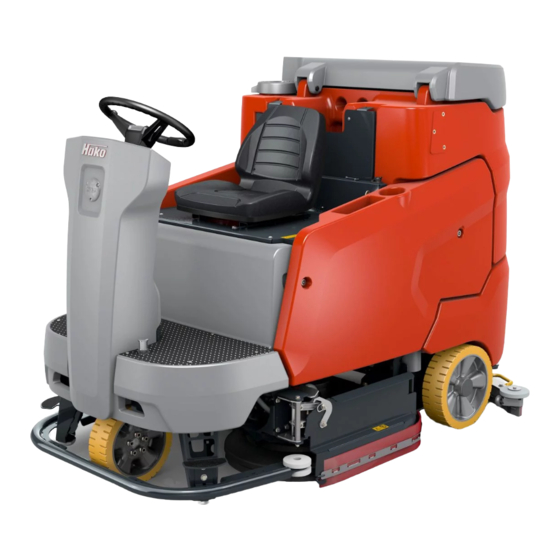
Page 20: Operation
Operation 2 Operation Overviews The description in chapter 2 contains information on the function and handling of the individual controls on the machine. The controls always have the same item number in all chapters. Fig. 4: 02-7182-01.fm... -
Page 21: Front View
Operation 2.1.1 Front view Item Designation Steering wheel Driver's seat Tray Flashlight on a pole Key for electronics cover Key for side panelling Holder for manual suction tool or manual spray suction tool Drinks holder and storage compartment Socket for USB connection Side panelling Ball cock Fresh water filter... - Page 22 Operation Fig. 5: 02-7182-01.fm...
-
Page 23: Rear View
Operation 2.1.2 Rear view Item Designation Accelerator pedal On-board dosing system Brush unit Wiper Solution tank Maintenance opening solution tank Squeegee water connection Fresh water drain hose Squeegee Suction hose Drain hose waste water Waste water tank maintenance opening Water connection Spray nozzle Battery compartment Battery plug... -
Page 24: Control Panel
Operation Fig. 6: 2.1.3 Control panel Item Designation Multifunction display Return button Turn-push knob Button – brush unit Button – squeegee Button – fresh water supply Button – boost function Button – brush unit and squeegee Button – driving direction selection iButton Reader (option) 02-7182-01.fm... - Page 25 Operation Key switch Button – signal horn Button – speed reduction forwards gear Button – silent operation Button – tool operation Button – pre-sweep suction unit Button – side brush unit 02-7182-01.fm...
-
Page 26: Controls And Display Elements
Operation Controls and display elements 2.2.1 Control panel The individual functions of the buttons on the control panel are described below. The respective activated functions are visible as corresponding symbols in the multifunction display. Key switch Fig. 6-51 The electrical system is switched on and off with the key switch. •... - Page 27 Operation Speed reduction button Fig. 6-53 The maximum speed when driving forwards is reduced by approx. 50 % with this button. • Push the button: Speed reduction ON • Push the button again: Speed reduction OFF Signal horn button Fig. 6-52 The signal horn is switched on and off with this button.
- Page 28 Operation Brush unit button Fig. 6-44 The brush unit is lowered and raised with this button. • Push the button: The brush unit is lowered. When actuating the accelerator pedal, the brush drive and the water supply are switched on. •...
- Page 29 Operation Brush unit and squeegee button Fig. 6-48 The brush and suction turbine drive are switched on and off simultaneously with this button. • Push the button: the brush unit, the side brush unit and the squeegee are lowered, and the suction turbine is switched on. The brush drive and the water supply are switched on when the accelerator pedal is actuated.
- Page 30 Operation Tool operation button Fig. 6-55 The following tools can be switched on and off using this button when the driver is not on the seat: • Spray nozzle • Manual suction or spray suction tool If the machine does not have a particular tool, it is excluded from the switching order •...
-
Page 31: Multifunction Display
Operation Multifunction display The functions and indicators of the machine are set and displayed with the multifunction display. After the machine is switched on, the operating system and data are loaded and the start screen appears on the display. After several seconds the view changes, and the main menu Fig. -
Page 32: Main Menu
Operation 2.3.2 Main menu The main menu is divided up into three levels. • Status level Fig. 8-A • Function level Fig. 8-B • Action level Fig. 8-C Fig. 8: Symbols at status level Symbol Designation Meaning Service alarm Service alarm clock active. clock Service alarm If the service alarm clock has elapsed, this symbol is... - Page 33 Operation Speed reduction The symbol is displayed when the machine is driving at reduced speed. Parking brake The symbol is displayed when the parking brake is activated. Rear wheel parking The symbol appears if the rear brake has been taken brake is not out of service mechanically.
- Page 34 Operation Symbols at function level All active units are displayed as symbols at function level. Symbol Designation Meaning Side brush unit Side brush unit active. Pre-sweep Pre-sweep suction unit active. suction unit Speed-independent The selected water dosing is displayed in the water dosing bar diagram.
- Page 35 Operation Solution tank full The current filling level of the solution tank is shown descending in steps of 20 %. Warning symbol The symbol appears when the filling level of the – solution tank solution tank is approximately 10 litres. A warning empty sound is additionally output.
- Page 36 Operation Action level Settings can be made or actions performed in the action level using soft keys Fig. 6-A to G. Fig. 9: The soft keys are selected by rotating the turn-push knob (soft key with yellow border) and confirmed by pressing. An action window Fig. 9-H opens, in which the settings can be carried out using the turn-push knob.
- Page 37 Operation Setting the mixing ratio, see section 3.4.2. On-board dosing system Ejecting the rotating brushes, see section 5.5.3. Ejecting the rotating brushes Replacing Roller brush change position, the roller brushes Coupling the rotating brushes, see section 5.5.4. Coupling the brushes Working light ON/OFF by means of direct selection using Working the soft key.
-
Page 38: Sub-Menu
Operation 2.3.3 Sub-menu Configuration can be carried out, operating data read off and the clock/calen- dar set in the sub-menu. Some sub-menus require additional access rights. After calling up the sub-menu, the cursor automatically jumps to the operating hours menu. To return to the main menu, press •... - Page 39 Operation The following sub-menus can be selected: Operating hours meter menu Fig. 10-B • As well as the machine activation time and work mode, the operating hours of the individual units are displayed. • The remaining time until the next service is displayed in hours/days at the bottom right.
- Page 40 Operation Maintenance menu Fig. 10-C continued • Fast-fill menu ON • Program continues to the end and finishes automatically see section 3.4.2 Time/Date menu Fig. 10-D Time: • Choice between 12 hour or 24 hour display. • Set the clock in hours and minutes. Date: Set the date: day, month and year.
- Page 41 Operation Configuration menu Fig. 10-F The following settings are made in the configu- ration menu: • Activate/deactivate options. • Setting of machine-specific parameters. Making changes to the configuration menu requires additional access rights. Service information menu Fig. 10-G The last 10 items of service information are displayed in the service information menu.
-
Page 42: Controls At The Machine
Operation 2.3.4 Controls at the machine Fig. 11: Operating brake Fig. 11-17 When the accelerator pedal is released, the machine comes to a stop due to the braking effect of the travel drive. If this braking effect is not sufficient, the operating brake can be applied in addition. - Page 43 Operation Fig. 12: Side panelling Fig. 12-10 The trough batteries and the suction turbines are behind the side panelling. The side panelling can be easily removed using the provided wrench. Waste water tank maintenance opening Fig. 12-31 The maintenance opening is used to drain the waste water and for cleaning the tank.
-
Page 44: Functional Description
Operation Functional description: Scrubmaster B260 R is a ride-on scrubber-drier for wet cleaning hard floor surfaces. The Scrubmaster B260 R is intended for economical cleaning of large operational areas. In cleaning mode, the cleaning solution is supplied from the solution tank to the rotating brushes in the brush unit. -
Page 45: Rotating Brush And Roller Brush Unit
Operation 2.4.2 Rotating brush and roller brush unit The brushes in the brush unit Fig. 13-22 are, depending on the actual version, driven by two or three electric motors. The brush unit is lowered with the Brush unit Fig. 6-44 button. When actuating the accelerator pedal, the brush motors and the water supply are switched on. -
Page 46: Squeegee
Operation 2.4.5 Squeegee The movable, hinged squeegee Fig. 13-28 is lowered and switched on with the Squeegee button Fig. 6-45. The squeegee withdraws the waste water from the floor using a sealing strip. The suction turbines vacuum the waste water from the floor. If the machine passes through narrow sections, e.g. -
Page 47: Travel Drive
• Trough battery 36 V/420 Ah PzV, 320 A maintenance free Battery management system (BMS) The Scrubmaster B260 R is fitted with a BMS. The BMS ensures that the battery system is monitored. The BMS is responsible for: • determining the battery charging state during operation •... -
Page 48: Operation
Instruction Instruction is required before the first start-up. The first-time instruction of the machine must be provided only by a specialist of your authorised Hako dealer. This person will be notified immediately after delivery of the machine from the factory and will contact you to make an instruction appointment. -
Page 49: Driver's Seat
Operation 3.3.1 Driver's seat Attention For reasons of safety, the driver's seat is equipped with a seat contact switch. The function of the seat contact switch must not be bypassed. Danger Do not adjust the driver’s seat while driving. Risk of accident! •... -
Page 50: Side Mirror (Optional) Adjustment
Operation Adjust in longitudinal direction • Push lever Fig. 17-A outwards. • Move seat forwards or backwards. • Release lever Fig. 17-A and let the driver's seat engage. Adjusting the tilt of the backrest Adjust the tilt of the backrest by turning the handwheel Fig. 17-B. Adjusting the tilt of the armrests Adjust the tilt of the armrests by turning the wheel Fig. -
Page 51: Cleaning
Operation Cleaning Attention • Before operating the machine, read and observe the safety instructions in chapter 1. • The machine can only be put into service when the driver is sitting on the driver's seat. • The travel drive can only be started if the accelerator pedal is not being actuated when the machine is turned on. -
Page 52: Entry.x (Optional)
Operation 3.4.1 Entry.X (optional) Access authorization is allocated using entry.X. Entry.X can only be used with view.X.live. Fig. 19: Putting into service 1. Turn the machine on with the key switch Fig. 19-A. • Red LED of the iButton Reader ON. 2. -
Page 53: On-Board Dosing System (Option)
Operation 3.4.2 On-board dosing system (option) The on-board dosing system is used for optimum dosing of the detergent. Attention Only use detergents suitable for automatic machines (foam retarded). We recommend use of our detergents and care agents specifically developed for the machines. These products meet the requirements of the German Detergent and Detergent Act (WRMG). - Page 54 Operation Setting the mixing ratio In the action window, the mixing ratio of detergent/fresh water can be selected in 9 steps. Basic setting = 1:100 Mixing ratio Detergent in the fresh water 1:700 0.1 % 1:500 0.2 % 1:300 0.3 % 1:200 0.5 % 1:150...
-
Page 55: Useful Cleaning Tips
Operation 3.4.3 Useful cleaning tips Sweep the floor before carrying out wet cleaning. This not only enhances the cleaning effect but also reduces wear of the machine's working tools. If the floors are really dirty or wax needs to be removed, treat the floor twice. In the first step, scrub the floor with a detergent suitable for the degree of soiling;... -
Page 56: Handling And Braking The Vehicle
Operation 3.4.4 Handling and braking the vehicle Note Set the key switch to ‘0’ to immediately disable all the functions. Danger • Danger of tilting over when driving on excessively steep slopes Transport journeys on slopes of up to 10 % must only take place for a limited period of time and with special caution. -
Page 57: Pushing The Machine
After pushing the machine, do not re-start until the lever(s) has (have) been positioned and the cover has been fitted. If the machine stops on an uphill or downhill gradient, call the towing service or Hako service! Fig. 22: In order to push the machine, carry out the following steps: 1. -
Page 58: Turning Off The Machine
Operation 3.4.6 Turning off the machine 1. Slowly bring the accelerator pedal to the zero position. The machine slows down to standstill. A better braking effect is achieved when the machine is slowed down by applying the brake. 2. When the machine is at standstill, the parking brake is activated audibly. 3. -
Page 59: Loading And Transporting
Operation Loading and transporting Attention • When loading and subsequently transporting the machine to the work site, the squeegee and brush head must be raised. Fresh and waste water tank must be empty! • Risk of skidding! Drive very carefully and, if possible, only on dry ramps. -
Page 60: Service Information
(tool key). The table below explains the most important service codes. Eliminate the cause or note down the service code and inform your authorised Hako service partner. If the cause has been eliminated, the fault must be acknowledged via the key switch OFF/ON. - Page 61 Operation Service Fault Cause Remedy code 2.3.5.1/ Side brushes stop Foreign particle blocks the Inspect the side 2.3.6.1/ side brushes brushes for foreign particles and remove them if necessary 2.3.6.4 Side brush arm lift sys- Overloading or foreign Inspect for foreign tem stops particles between side arm particles and remove...
-
Page 62: Technical Data
Technical data 4 Technical data Dimensions Name Unit Length of machine with squeegee without/with 2020/2790 pre-sweep unit Width of machine without/with squeegee: 1150/1290 with rotating brush 1080 1290/1290 with rotating brush 1230 1210/1290 with roller brush 1080 Height of machine without/with overhead guard 1490/2090 Working width Brush unit:... - Page 63 Technical data Driving performance Name Unit Driving speed transportation (forwards/reverse) km/h Climbing capacity when cleaning: Front-wheel drive 6 (2 min.) X-AC drive 15 (up to 5 min. at 4 km/h) Climbing capacity during transport journey (ready for operation): Front-wheel drive 10 (1 min.) X-AC drive 18 (3 min at 4 km/h)
- Page 64 Technical data Vacuum system Name Unit Air quantity suction turbines approx. 200 Vacuum (maximum) mbar approx. 170 Electrical system Nominal voltage Nominal output (max.) (P1): Front-wheel drive with 2-rotating brush unit 1080 5668 Front-wheel drive with 3-rotating brush unit 1080 or 1230 6604 Front-wheel drive with roller brush unit and side brush 6763...
- Page 65 Technical data Name Unit Sweeping level width 45±10 Side brush diameter Side brush speed Theoretical sweeping capacity m²/h 10400 Dirt hopper volume (maximum load 20 kg) Litres Filter area m² Filter use category ZH 1/487 Drive motor (P1) Nominal voltage Permissible total weight Noise emission value B260 R rotating...
-
Page 66: Maintenance And Servicing
Daily and weekly maintenance and repair work can be undertaken by a driver trained for this purpose. For all other maintenance work, see service booklet, please contact your nearest Hako service centre or authorised Hako dealer. Any warranty claim is null and void if this is not complied with and damage results. -
Page 67: Maintenance Plan
Maintenance and Servicing Maintenance plan Hako system maintenance customer: Work to be performed by the customer by reference to the servicing and maintenance instructions specified in the operating manual. Daily • Emptying the waste water tank • Clean the waste water tank, drain hose, coarse dirt sieve and suction filter •... -
Page 68: Battery
Maintenance and Servicing Battery 5.2.1 Checking the charging state Fig. 24: The charge condition of the battery Fig. 24-A is displayed on the multifunction display during operation. Depending on the charge condition, the following symbols appear: Symbols Charging state Notes Battery is fully charged Battery capacity is... -
Page 69: Charge The Battery
• Before initially starting up the machine, the battery that is used must be fully and properly charged with commissioning charge. Please observe the instruction manual of the charging device and the instruction manual of the battery manufacturer. Hako assumes no liability for battery damage resulting from insufficient commissioning charge. - Page 70 Fig. 25-A. The batteries can be charged if the battery capacity is less than 60 %. Note For safe charging, the Hako charger and the battery have a safety circuit (pilot contact control unit). The charger (99400110) can only charge batteries that have the PCCU circuit Fig.
-
Page 71: Checking The Acid Level
• Refilling must only take place once the battery charging process has been terminated. Note Batteries approved by Hako are equipped with an aquamatic system. Fig. 26: Checking the acid level: If the trough battery is equipped with an aquamatic system Fig. 26-A, each individual cell features a sealing plug with float indicator. -
Page 72: Replacing The Battery
Maintenance and Servicing 5.2.4 Replacing the battery Attention • Only use batteries approved by Hako at the intended position! • The battery should only be replaced by qualified service personnel! • Wear safety shoes when changing the battery. • Only change the battery using suitable lifting gear and crane gear with a sufficient load-bearing capacity. -
Page 73: Battery Plug Coding
See connecting diagram Fig. 27-B. 5.2.5 Battery plug coding When using other batteries which have been approved by Hako, the plugs must be re-coded. The plug connectors between the battery Fig. 28-A, the machine Fig. 28-B and the charger Fig. 28-C are coded with coloured coded pins (yellow, grey or green) Fig. -
Page 74: Maintaining Drive Batteries
Maintenance and Servicing 5.2.6 Maintaining drive batteries For maintaining and servicing drive batteries, see Hako supplementary sheet 88-60-2556 – Information for drive batteries and the operating manual of the battery manufacturer. 5.2.7 Taking the machine out of service for a long period If the battery is not used for more than three months, the battery must be recharged. -
Page 75: Solution Tank
Maintenance and Servicing Solution tank The filling level in the solution tank is measured continuously and shown in the multifunction display in steps of 20 %. If there are less than 10 litres in the tank, a warning symbol Fig. 29-A appears in the multifunction display. At the same time, an acoustic warning is heard and indicates that a top-up is required. - Page 76 Maintenance and Servicing Filling the solution tank with the fast fill station The filling opening of the solution tank can be increased when filling with the fast fill station by unscrewing the grey cover Fig. 31-A and removing it Fig. 31-B. Fig.
-
Page 77: Emptying The Solution Tank
Maintenance and Servicing 5.3.2 Emptying the solution tank Fig. 33: 1. Drive to a suitable disposal centre. 2. Position the machine, ensuring the drain hose Fig. 33-27 reaches the drain in the ground. 3. Turn off the machine. 4. Remove the drain hose from the holder, open the drain valve Fig. 33-A and drain the waste water tank via the drain. -
Page 78: Waste Water Tank
Maintenance and Servicing Waste water tank 5.4.1 Emptying the waste water tank Clean the waste water tank Fig. 35-37 daily or as required. When the symbol Waste water tank full Fig. 34-A appears in the display panel and an acoustic warning signal is output, the suction functions are switched off and the waste water tank should be drained immediately. -
Page 79: Cleaning The Waste Water Tank
Maintenance and Servicing 5.4.2 Cleaning the waste water tank Clean the waste water tank daily or as required. Fig. 35: 1. Empty the waste water tank, see section 5.4.1. 2. Open fastener at drain hose Fig. 35-A and remove hose. 3. -
Page 80: Cleaning The Coarse Dirt Sieve
Maintenance and Servicing 5.4.3 Cleaning the coarse dirt sieve A coarse dirt sieve Fig. 36-36 is optionally located in the waste water tank.Clean the sieve daily and as required. Fig. 36: 5.4.4 Cleaning the intake sieve Check the function of the intake sieve Fig. 37-38 daily and clean it as required. -
Page 81: Cleaning The Fresh Water Filter
Maintenance and Servicing 5.4.6 Cleaning the fresh water filter Check the filter sieve Fig. 39-A of the fresh water filter Fig. 39-12 weekly and clean or replace it as required. Fig. 39: 1. Close the ball cock Fig. 39-B. 2. Turn and remove the filter cover Fig. 39-C. 3. -
Page 82: Rotating Brush Unit
Maintenance and Servicing Rotating brush unit Fig. 41: 5.5.1 Replacing the brushes/pads Use the indicator Fig. 41-A on the rotating brush unit to: • determine the wear of the brushes/pads (the rotating brush unit must be lowered), • determine whether the brushes/pads have been assembled. The brushes/pads must be changed when the pointer Fig. -
Page 83: Ejecting The Brushes/Pads
Maintenance and Servicing 5.5.3 Ejecting the brushes/pads Fig. 42: 1. Make sure that the rotating brush unit has been raised and the machine is stationary. 2. Select soft key Eject brushes Fig. 42-A using the turn-push knob and confirm. The action window Fig. 42-B opens. Use the turn-push knob to confirm the start. -
Page 84: Side Brush Unit (Optional)
Maintenance and Servicing Side brush unit (optional) Fig. 44: 5.6.1 Adjusting the side brush Side brush tilt The tilt of the side brush Fig. 44-A is preset in the factory and cannot be changed. Readjusting the side brush position Check side brush weekly for wear. In the event of wear or after changing the side brush, adjust as follows: 1. -
Page 85: Changing The Side Brush
Maintenance and Servicing 5.6.2 Changing the side brush Fig. 45: Assembling the side brush 1. Place the machine on a level surface. 2. Raise the side brush unit with key Side brush unit Fig. 44-57. 3. Fit the side brush Fig. 45-A to the hub Fig. 45-B. 4. -
Page 86: Squeegee
Maintenance and Servicing Squeegee Optimum vacuuming is achieved through: • clean and undamaged or not worn sealing strips • correctly set inclination angle and correct height adjustment of the sealing strips. 5.7.1 Cleaning the squeegee Check the squeegee Fig. 47-28 daily for soiling and foreign particles and clean it as required. - Page 87 Maintenance and Servicing Fig. 47: Daily cleaning in the event of light soiling External water connection: 1. Sit on the seat of the machine and switch on the machine. 2. In the sub-menu, call up menu item Maintenance page Fig. 47-A. Select soft key Squeegee cleaning Fig.
-
Page 88: Changing The Sealing/Slot Strip
Maintenance and Servicing 5.7.2 Changing the sealing / slot strip Check the sealing strip Fig. 48-A and the slot strip Fig. 48-B at the squeegee weekly for wear and damage. If the used sealing edge of the strip is worn or damaged, turn or replace the strip. -
Page 89: Adjusting The Sealing Strips
Maintenance and Servicing 5.7.3 Adjusting the sealing strips Inclination adjustment The correct inclination adjustment is decisive for: • ensuring that the sealing strips of the squeegee rest evenly with the complete contact surface on the ground. • ensuring that the squeegee runs smoothly and evenly during the suction process. - Page 90 Maintenance and Servicing Height adjustment The height adjustment (X) of the supporting rollers Fig. 51-A has been set to 7 mm in the factory. If striping still occurs despite optimum inclination adjust- ment, readjust the distance between the supporting rollers and the lower edge of the sealing strip.
-
Page 91: Wiper
Maintenance and Servicing Wiper Fig. 52: 5.8.1 Changing the wiper rubber Check the rubber of the wiper Fig. 52-A weekly for wear, turn or replace the rubber if necessary. 1. Loosen the wing nut Fig. 52-B. 2. Remove the clamping band Fig. 52-C. Turn the rubber of the wiper (can be used 4 times) or replace it. -
Page 92: Pre-Sweep Suction Unit (Optional)
Maintenance and Servicing Pre-sweep suction unit (optional) 5.9.1 Emptying the dirt hopper Check the fill level of the dirt hopper at regular intervals (max. load 20 kg) and empty if necessary. Fig. 53: 1. Turn off the machine. 2. Pull the dirt hopper Fig. 53-A upwards using the handle Fig. 53-B and dispose of the contents in an environmentally friendly way. -
Page 93: Shaking The Filter
Maintenance and Servicing 5.9.3 Shaking the filter Clean the filter Fig. 54-B several times per day using the shaking system Fig. 53-D. To clean the filter, pull out the lever of the shaking system several times and slide back in again. 5.9.4 Cleaning the filter Danger... -
Page 94: Cleaning The Cylindrical Brush And The Cylindrical Brush Compartment
Maintenance and Servicing 5.9.5 Cleaning the cylindrical brush and the cylindrical brush compartment Inspect the cylindrical brush Fig. 55-A and the cylindrical brush compartment for soiling daily and clean if necessary. Fig. 55: 1. Disconnect the pre-sweep suction unit from the machine. 2. -
Page 95: Adjusting The Sweeping Level
Maintenance and Servicing 5.9.7 Adjusting the sweeping level In the event of bristle wear and after replacing the cylindrical brush, the sweeping level Fig. 55-A must be readjusted. Note Mark the floor with chalk to check the sweeping level. Fig. 56: 1. -
Page 96: Changing The Side Brush
Maintenance and Servicing 5.9.9 Changing the side brush Inspect the side brushes once per week and replace if wear is present. 9:00 3:00 Fig. 57: 1. Switch off the machine and remove the dirt hopper Fig. 57-A. 2. Remove both M6x16 flanged button head bolts, the brush adjuster and the cover Fig. -
Page 97: Attachments/Options
Attachments/options 6 Attachments/options Spray suction tool The spray suction tool Fig. 58-A is used for manually cleaning difficult-to-reach points. Attention • The spray suction tool is used to suck up dust. Only suck with the addition of water! • Do not use the spray suction tool while driving! Note Before starting up for the first time, the provided adapter must be securely attached to the end of the hose Fig. -
Page 98: Manual Suction Tool
Attachments/options Manual suction tool: The manual suction tool Fig. 59-A is used for manually cleaning difficult-to-reach points. Attention • The manual suction tool is not used to suck up dust. Only suck up water! • Do not use the spray suction tool while driving! Fig. -
Page 99: Spray Nozzle
Attachments/options Spray nozzle The spray nozzle Fig. 60-33 is used to flush the solution tank and waste water tank. Fig. 60: 1. Connect the hose to the water connection of the machine Fig. 60-A. 2. Use the Tool operation button Fig. 60-55 on the control panel to turn the water supply on and off. -
Page 100: Pre-Sweep Suction Unit
Attachments/options Pre-sweep suction unit The pre-sweep suction unit picks up dirt in the dry area in front of the scrub- bing unit. The two side brushes brush the dirt directly into the path of the cylin- drical brush. The cylindrical brush then sweeps the dirt forwards into the dirt hopper. -
Page 101: Check And Correct Settings
Attachments/options 6.4.2 Check and correct settings With overhead guard Without overhead guard Fig. 62: If the pre-sweep suction unit is attached to the machine and the lever is in the sweeping position (Pos. 1) Fig. 61-A, the frame must be aligned parallel to the floor. -
Page 102: Sweeping Operation
Attachments/options 6.4.3 Sweeping operation Attention • Do not use the pre-sweep suction unit unless the dirt hopper is attached! • Sweeping up dust that is hazardous to health is not permitted! • Ensure that there is sufficient ventilation when performing sweeping tasks in enclosed rooms! Fig. -
Page 103: Parking The Pre-Sweep Suction Unit
Attachments/options 4. Check the cylindrical brush compartment for contamination and remove if necessary. 5. Clean the pre-sweep suction unit if necessary. 6.4.6 Parking the pre-sweep suction unit Fig. 64: 1. Unplug the plug at the machine side and plug into the retaining hole Fig. -
Page 104: Blue Spot
Attachments/options Blue Spot The Blue Spot Fig. 66-A is a visual warning device. A blue spot projected onto the ground warns people and vehicles of approaching machines. In addition, a warning signal can be output, see page 37. Danger Possible eye injury! •... -
Page 105: Ec Declaration Of Conformity
Hamburger Str. 209-239 23843 Bad Oldesloe, Germany declare in sole responsibility that the following products Scrubmaster B260 R model: 7182 Pre-sweep suction unit model: 7180.50 to which this declaration relates correspond with the relevant basic safety and health requirements of EC Directive 2006/42/EC as well as the requirements according to 2014/30/EC and 2014/53/EC.
Need help?
Do you have a question about the Scrubmaster B260 R and is the answer not in the manual?
Questions and answers