
Related Manuals for HAKO Scrubmaster B75R


Summary of Contents for HAKO Scrubmaster B75R
- Page 1 Cleaning Technology · Municipal Technology Scrubmaster B75 R (7175) Operating Manual Issue: 09.2015 Book number: 88-00-3046...
-
Page 2: Introduction
We have provided the places in this operating manual concerning your safety with a danger pictogram. Your authorised Hako dealer is available at all times to answer further questions about the vehicle or the operating manual. - Page 3 Maintenance work must be carried out by an authorised Hako service workshop and confirmed in the Maintenance Report, which serves as a warranty logbook.
- Page 4 Machine data Your machine is described clearly by the following data. Please always quote these data in correspondence or when making a telephone query to your authorised Hako dealer or our company. • Machine type • Manufacturing no. • Start-up on: Your nearest authorised Hako dealer: •...
-
Page 5: Table Of Contents
Table of contents Introduction..............2 Safety instructions ............8 Marking of warning and danger symbols ......8 General safety instructions ..........9 Operating safety instructions ........... 9 Maintenance instructions ..........11 Information about special risks ........12 Environmental protection instructions and disposal ..14 Labels on the machine .......... - Page 6 Table of contents Technical data..............41 Maintenance and Servicing .......... 44 Maintenance certificate ..........45 Maintenance plan ............46 Battery system ............... 49 5.3.1 Type of battery ............... 49 5.3.2 Battery management system (BMS) ......50 5.3.3 Checking the charging state .......... 50 5.3.4 Charging the batteries (7175.1x/.2x) ......
- Page 7 Table of contents Options ................70 5.8.1 On-board chemical metering system ......71 5.8.2 Working spotlight ............72 5.8.3 Warning device forwards gear ........72 5.8.4 Coarse dirt sieve of waste water tank ......72 5.8.5 Wiper and squeegee 760 ..........73 5.8.6 Tray ................
-
Page 8: Safety Instructions
Safety instructions 1 Safety instructions Warning and danger symbols Important tasks concerning the safety of the operator and machine are named as follows in this operating manual and emphasised by symbols. Danger Indication of a direct danger with high risk, in which death or severe physical injury can occur if it is not avoided. -
Page 9: General Safety Instructions
Please observe the operating manual of the charger and the operating manual of the battery manufac- turer. Hako assumes no liability for battery damage resulting from insuffi- cient commissioning charge. • Check the machine for operating safety before every start-up! Eliminate faults immediately. - Page 10 Safety instructions During operation • Sturdy and slip-proof shoes must be worn when working with the machine. • Only those surfaces approved by the contractor or its authorised represent- ative for use of the machine may be driven on. • Never use the machine at places where objects can fall down. •...
-
Page 11: Maintenance Instructions
• Daily and weekly maintenance work must be done in accordance with the maintenance plan by the operating staff. In all other maintenance work, please contact your nearest Hako service centre. • The maintenance work and maintenance intervals specified in the operating manual must be complied with. -
Page 12: Information About Special Risks
• Only instructed maintenance personnel must handle and replace batteries. • Only batteries approved by Hako may be used at the intended position. • Danger! Make sure that the insulation of the battery cables is not damaged. - Page 13 Have a qualified electrician replace the mains cable. • Make sure that no water or liquid can come into contact with live parts. If water has still entered parts, immediately disconnect the mains plug and have the machine checked by the authorised Hako service. 01-7175-00-00.fm...
-
Page 14: Environmental Protection Instructions And Disposal
Return and recycling have to be arranged with the authorised Hako dealer as required in § 6 and § 8 of the German battery law (BattG)! -
Page 15: Labels On The Machine
Safety instructions Labels on the machine The following safety and instruction labels are affixed to the machine in a clearly visible and legible manner. Attention Renew missing or illegible labels immediately! Fig. 1: 01-7175-00-00.fm... - Page 16 Safety instructions Fig. 2: Label – Logo Fig. 1-A The Hako logo is located at the front on the steering column and at the rear on the hopper. Label – Type plate Fig. 1-B The type plate is located on the left hand side of the chassis in front of the rear wheel.
- Page 17 Safety instructions Label – 24 V Fig. 1-D The label is located on the left hand side of the battery compartment. Label – Maintenance-free batteries Fig. 1-E The label is located on the left hand side of the battery compartment. Label –...
-
Page 18: Operation
Operation 2 Operation Overviews The description in chapter 2 contains information on the function and handling of the individual controls on the vehicle. The controls always have the same item number in all chapters. Fig. 3: 02-7175-00-00.fm... -
Page 19: Front View
Operation 2.1.1 Front view Item Designation Steering wheel Mains cable on-board charger Driver's seat Cover with vacuum system Filling opening solution tank Level indicator solution tank Solution tank Foot lever brush decoupler Brush head On-board chemical metering system (option) Parking brake Operating brake Travel drive Working spotlights (option) - Page 20 Operation Fig. 4: 02-7175-00-00.fm...
-
Page 21: Rear View
Operation 2.1.2 Rear view Item Designation Suction filter Waste water tank Coarse dirt sieve (option) Maintenance opening solution tank Adjusting lever fresh water metering Accelerator pedal Wiper (option) Fresh water filter Squeegee Drain hose waste water Manual suction tool, including holder (option) Suction hose squeegee Tray (option) Automatic filling unit (option) -
Page 22: Control Panel
Operation Fig. 5: 2.1.3 Control panel Item Designation Display panel Button – chemical metering system (option) Button – squeegee / manual suction tool (option) Button – brush head Button – brush head and squeegee Button – speed reduction forwards gear Driving direction selector switch Key switch Button –... -
Page 23: Display Panel
Operation Fig. 6: 2.1.4 Display panel Item Designation Meaning Fresh water supply The symbol is displayed when the fresh water supply is switched on and the brush head is lowered. Number field Display panel for: -Operating hours meter -Service code -Release indicator for Fleet-Recorder option -Counter for brush decoupling Speed reduction... - Page 24 Operation Indicator – battery If the machine is ready for use, the current management system charging state of the batteries is displayed. (BMS) and charging When the battery is charged, the charge con- process trol indicator appears in the display panel (7175.1x/.2x).
-
Page 25: Controls And Display Elements
Operation Controls and display elements 2.2.1 Control panel The individual functions of the buttons on the control panel are described below. The respective activated functions are visible as corresponding symbols in the display panel. Key switch Fig. 5-40 The electrical system is switched on and off with the key switch. •... - Page 26 Operation Speed reduction button Fig. 5-38 The maximum speed when driving forwards is reduced by approx. 50 % with this button. • Push the button: Speed reduction ON • Push the button again: Speed reduction OFF Signal horn button Fig. 5-41 The signal horn is switched on and off with this button.
- Page 27 Operation Brush head button Fig. 5-36 The brush head is lowered and raised with this button. • Push the button: The brush head is lowered. When actuating the accelerator pedal, the brush drive and the water supply are switched on. •...
- Page 28 Operation Warning device button (option) Fig. 5-42 Two functions can be selected with this button: • Push the button once: Warning lamp flashes • Push the button twice: Warning lamp flashes. A warning signal is additionally output when driving forwards. •...
-
Page 29: Controls At The Machine
Operation 2.2.2 Controls at the machine Fig. 7: Mains connection Fig. 7-2 The mains connection supplies voltage to the charger. Filling opening fresh water Fig. 7-5 The solution tank is filled via a hinged filling opening. Optionally, the solution tank can be filled via the automatic filling unit, see section 5.8.7. - Page 30 Operation Fig. 8: Maintenance opening Fig. 8-20 The maintenance opening is used to drain the fresh water and clean the solution tank. Adjusting lever fresh water metering Fig. 8-21 Metering of the fresh water to the brush head is set using the adjusting lever. The water quantity can be set between 0.8 l/min and 3.3 l/min.
-
Page 31: General Principle Of Operation
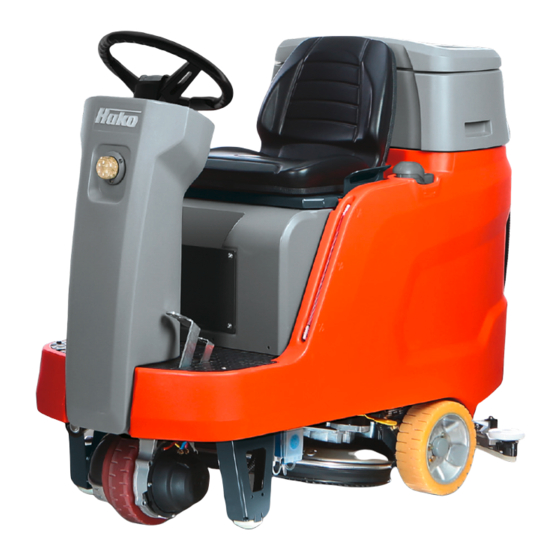
Operation General principle of operation Scrubmaster B75 R is a ride-on scrubber-drier for wet cleaning hard floor surfaces. In cleaning mode, the cleaning solution is supplied from the solution tank to the rotating brushes in the brush head. Fresh water metering takes place manually via an adjusting lever. -
Page 32: Squeegee
Operation 2.3.3 Squeegee The movable, hinged squeegee Fig. 9-25 is lowered and switched on with the squeegee button Fig. 5-35. The squeegee withdraws the waste water from the floor using a sealing strip. The suction turbine vacuums the waste water from the floor. -
Page 33: Putting Into Service
Instruction Instruction is required before the first start-up. The first-time instruction of the machine may be provided only by a specialist of your authorised Hako dealer. This person will be notified immediately after delivery of the machine from the factory and will contact you to make an instruction appointment. -
Page 34: Installing The Mains Cable
Putting into service 3.3.1 Installing the mains cable Fig. 11: 1. Remove the cover Fig. 11-A. 2. Route the cable of the mains plug Fig. 11-B through the opening in the bracket Fig. 11-C. Ensure that the side of the strain relief without a latch faces the front towards the opening. -
Page 35: Cleaning
Putting into service Cleaning No. Description Turn on the machine Select the driving direction via the driving direction selector switch Select the cleaning programme Loosen the parking brake and actuate the accelerator pedal. The brushes and water supply are switched on. Adjust the fresh water quantity as required using the adjusting lever of the fresh water metering system. -
Page 36: Useful Cleaning Tips
Putting into service 3.4.2 Useful cleaning tips Sweep the floor before carrying out wet cleaning. This not only enhances the cleaning effect but also reduces wear of the machine's working tools. If the floors are really dirty or wax needs to be removed, treat the floor twice. In the first step, scrub the floor with a cleaning agent suitable for the degree of soiling;... -
Page 37: Checklist - After Cleaning
Putting into service 3.4.4 Checklist – after cleaning Environmental danger Observe the applicable laws and local regulations when disposing of cleaning agents. No. Description Drive to a suitable maintenance location Turn off the machine, remove the key and engage the parking brake Empty and flush the waste water tank Check the fresh water filter (adjusting lever for fresh water metering must be set to 0) -
Page 38: Loading And Transporting
Putting into service Loading and transporting Attention • When loading and transporting the machine to the work site, the squeegee and brush head must be raised. • When loading the machine, reverse it (empty drive) up the ramp (maximum slope 18 %). •... -
Page 39: Service Code Tables
(tool key). The dots of the service code flash. Eliminate the error or note down the ser- vice code and inform your authorised Hako dealer. If the cause has been eliminated, the error must be acknowledged via the key switch OFF/ON. - Page 40 Putting into service Continued service code table Service Fault Cause Remedy code 3.3.1.1. Service interval See maintenance expired plan 3.4.1.2. Driving not Error in the drive control Turn the machine possible OFF/ON, contact the customer ser- vice if necessary 3.4.5.1. Cleaning function •...
-
Page 41: Technical Data
Technical data 4 Technical data Dimensions Name Unit 7175.1x 7175.2x 7175.30 Length of machine with squeegee 1475 1475 1475 Width of machine with squeegee Width of machine without squeegee Height of machine 1215 1215 1215 Working width Brush head Squeegee Weights Weight (empty, without batteries) Total weight (ready for use) - Page 42 Technical data Tank contents Name Unit 7175.1x 7175.2x 7175.30 Solution tank Litre Waste water tank Litre Brush head Number of brushes Piece Brush speed Brush contact pressure Vacuum system Air quantity Vacuum (maximum) mbar Electrical system Nominal voltage Nominal output (max.) (P1) 1800 2520 2520...
- Page 43 Technical data Noise emission value The sound power level (L wAd ) measured under the customary dB (A) conditions of use according to DIN EN 60335-2-72 is: The sound pressure level (L pA ) (at the ear of the driver) measured under the customary conditions of use according to dB (A) DIN EN 60335-2-72 is:...
-
Page 44: Maintenance And Servicing
Daily and weekly maintenance and repair work can be undertaken by a driver trained for this, all further Hako system maintenance work may be undertaken only by trained and qualified personnel. Please contact your nearest Hako service centre or authorised Hako dealer. -
Page 45: Maintenance Certificate
Maintenance and Servicing Maintenance certificate Handover Hako system maintenance I Hako system maintenance II 125 operating hours 250 operating hours Equipment Workshop stamp Workshop stamp Trial run Handover to customer Instruction performed on: performed on: performed on: at _______________ operating hours... -
Page 46: Maintenance Plan
Maintenance and Servicing Maintenance plan Hako system maintenance customer: Work to be performed by the customer by reference to the servicing and maintenance instructions specified in the operating manual. Activity / interval Daily • Empty the waste water tank, clean the waste water tank and the suction filter •... - Page 47 Maintenance and Servicing Hako system maintenance I: Performance by an expert of an authorised Hako workshop by reference to the machine-specific system maintenance. Activity / interval Every 125 hours • Check the battery and the charger • Check the vacuum capacity and sound level of the suction turbine •...
- Page 48 Maintenance and Servicing Hako system maintenance II: Performance by an expert of an authorised Hako workshop by reference to the machine-specific system maintenance. Activity / interval Every 250 hours • All maintenance work according to Hako system maintenance I • Check the deflecting rollers of the brush head for ease of operation, replace if necessary •...
-
Page 49: Battery System
Type of battery The machines are equipped with different maintenance-free battery systems. When using other batteries which have been approved by Hako, correspond- ing settings must be carried out in the configuration menu. These settings should only be carried out by a workshop authorised by Hako! -
Page 50: Battery Management System (Bms)
• Determining the battery charging state during operation • Switching off the cleaning functions when the discharge limit has been reached to protect the battery against total discharge When using other batteries which have been approved by Hako, the BMS must be reset. Attention... -
Page 51: Charging The Batteries (7175.1X/.2X)
• Before initially starting up the machine, charge the used batteries fully and appropriately with commissioning charge. Please observe the operating manual of the charging device and the operating manual of the battery manufacturer. Hako assumes no liability for battery damage resulting from insufficient commis- sioning charge. -
Page 52: Checking The Charging Process (7175.1X/.2X)
Maintenance and Servicing 5.3.5 Checking the charging process (7175.1x/.2x) Fig. 15: During the charging process, the charging progress is displayed in the display panel Fig. 15-51: • Field 1 permanently ON, running light in fields 2,3 and 4: Main charge <50 % charged battery capacity •... -
Page 53: Information On Quick-Charging Technology (Only 7175.30)
Maintenance and Servicing 5.3.6 Information on quick-charging technology (only 7175.30) • The daily operating period of the battery can be extended by using quick- charging technology, i.e. by using free time for interim charging. • At the beginning of the charging process, additional capacity, which is available immediately, is charged at a very high charge current for 25 minutes. -
Page 54: Charging The Battery (Only 7175.30)
Maintenance and Servicing 5.3.8 Charging the battery (only 7175.30) Attention • The number of quick charging processes is limited to four a day. More frequent utilisation may result in excessive heat and premature failure of the batteries. • Only charge the battery with the supplied quick-charger! Note •... -
Page 55: Replacing Batteries (All Variants)
5.3.9 Replacing batteries (all variants) Attention • Only use batteries approved by Hako at the intended position! • Only Optima YellowTop S4,2 must be used for variant 7175.30, otherwise the battery might be damaged. • Only use maintenance-free, sealed batteries! •... -
Page 56: Solution Tank
Maintenance and Servicing Solution tank Fig. 17: 5.4.1 Filling the solution tank Fill the solution tank Fig. 1 -7 before commencing work or as required. Fig. 18: 1. Place the machine on a level surface. 2. Remove the insert of the filling opening Fig. 18-A. 3. -
Page 57: Emptying The Solution Tank
Maintenance and Servicing 5.4.2 Emptying the solution tank Fig. 19: There are three options to empty the solution tank: Emptying the solution tank via the fresh water filter Position the machine ensuring the fresh water filter Fig. 19-24 is above a drain in the ground. -
Page 58: Cleaning The Solution Tank
Maintenance and Servicing Emptying the solution tank via the vacuum system This method is recommended if no drain is available and the waste water tank is empty. Fig. 20: 1. Turn off the machine and engage the parking brake. 2. Set the adjusting lever of the fresh water metering system Fig. 19-21 to 0. 3. -
Page 59: Cleaning The Fresh Water Filter
Maintenance and Servicing 5.4.4 Cleaning the fresh water filter Check the filter sieve Fig. 21-B of the fresh water filter Fig. 19-24 weekly and clean or replace it as required. Fig. 21: 1. Set the adjusting lever of the fresh water metering system Fig. 19-21 to 0. 2. -
Page 60: Waste Water Tank
Maintenance and Servicing Waste water tank Fig. 22: 5.5.1 Emptying the waste water tank Empty the waste water tank Fig. 22-18 daily, as required or when an acoustic signal is output (increased suction turbine speed). Environmental danger Observe applicable laws and local regulations when disposing of cleaning agents! Fig. -
Page 61: Cleaning The Waste Water Tank
Maintenance and Servicing 4. Remove the drain hose from the holder. Push the suction hose Fig. 23-A slightly to the side so that the waste water tank can be emptied fully via the drain hose. 5. Bend the squeeze nozzle in the front section Fig. 23-B. 6. -
Page 62: Cleaning The Suction Filter
Maintenance and Servicing 5.5.3 Cleaning the suction filter Check the function of the suction filter Fig. 24-17 daily and clean it as required. 1. Remove the suction filter from the neck. 2. Clean the suction filter under running water. 3. Mount the suction filter on the neck again. 5.5.4 Checking the gasket at the drain hose Fig. -
Page 63: Brush Head
Maintenance and Servicing Brush head 7175.1x 7175.2x/.30 Fig. 27: 5.6.1 Cleaning the brushes Clean the brushes Fig. 27-A in the brush head Fig. 27-9 daily or as required. 1. Decouple the brush, see section 5.6.3. 2. Thoroughly clean the brush under running water. 3. -
Page 64: Replacing The Brushes
Maintenance and Servicing 5.6.2 Changing the brushes Use the indicator Fig. 28-A on the brush head to: • determine the wear of the brushes. • determine whether the brushes have been assembled. Fig. 28: Change the brushes at the latest when the red pointer is in the red zone. 1. -
Page 65: Coupling The Brushes
Maintenance and Servicing 5.6.4 Coupling the brushes Variant 7175.1x: 1. Turn on the machine. 2. Position the brushes centrally to the brush head. 3. Push the brush head button Fig. 27-36 or the brush head and squeegee button Fig. 27-37. 4. -
Page 66: Squeegee
Maintenance and Servicing Squeegee Optimum vacuuming is achieved through: • Clean and undamaged or not worn sealing strips. • Correctly set inclination angle and correct height adjustment of the sealing strips. Fig. 30: 5.7.1 Cleaning the squeegee Check the squeegee Fig. 30-23 daily for soiling and foreign particles and clean it as required. -
Page 67: Replacing The Sealing Strips
Maintenance and Servicing 5.7.2 Replacing the sealing strips Check the sealing strip Fig. 31-G and slot strip Fig. 31-H at the squeegee weekly for wear and intactness. If the used sealing edge of the sealing strip is worn or damaged, turn or replace the sealing strip. Each sealing strip can be used four times before it needs replacing. -
Page 68: Adjusting The Sealing Strips
Maintenance and Servicing 5.7.3 Adjusting the sealing strips Inclination adjustment The correct inclination adjustment is decisive for: • Ensuring that the sealing strips of the squeegee rest evenly with the complete contact surface on the ground. • Ensuring that the squeegee runs smoothly and evenly during the suction process. - Page 69 Maintenance and Servicing Height adjustment The height adjustment (X) of the supporting rollers Fig. 34-F has been set to 3 mm in the factory. If striping still occurs despite optimum inclination adjust- ment, set the distance of the supporting rollers to the lower edge of the sealing strip by adjusting the number of washers under the supporting roller holder.
-
Page 70: Options
Maintenance and Servicing Options The following options are available for Scrubmaster B75 R. Item Designation Order no. On-board chemical metering system 7678.30 Working spotlight 7092.50 Warning device forwards gear 7091.50 Coarse dirt sieve 7060.50 Wiper and squeegee 760 7176.05 Hand suction tool, including holder 7036.60 Tray 7009.50... -
Page 71: On-Board Chemical Metering System
Maintenance and Servicing 5.8.1 On-board chemical metering system The on-board chemical metering system is used for optimum metering of the cleaning agent. Attention Only use cleaning agents suitable for automatic machines (foam retarded). We recommend use of our cleaning and care agents specifically developed for the machines. -
Page 72: Working Spotlight
Maintenance and Servicing 5.8.2 Working spotlight The working spotlight is used to enhance lighting of the working area and must be aligned accordingly. Use the button to switch the working spotlight on and off. • Push the button: Working spotlights ON •... -
Page 73: Wiper And Squeegee 760
Maintenance and Servicing 5.8.5 Wiper and squeegee 760 This option is recommended when the working area is larger than 790 mm. Fig. 37: • To replace the brushes, raise the wiper at the handle Fig. 37-A and swivel it to the side. •... -
Page 74: Automatic Filling Unit
Maintenance and Servicing 5.8.7 Automatic filling unit Optionally, the solution tank can be filled via the automatic filling unit. Attention According to DIN EN 1717, the automatic filling unit must not be operated without a system separator (operating manual). min. 2.5 bar max. -
Page 75: Fleet-Recorder Standard
Maintenance and Servicing 5.8.8 Fleet-Recorder Standard The Fleet-Recorder records operating times and further operating conditions of the machine. Fig. 39: Putting into service 1. Turn on the machine with the ignition key Fig. 39-A. • Red LED of the I-Button ON. 2. -
Page 76: Ec Declaration Of Conformity
EC Declaration of Conformity (corresp. to the EC Directive 2006/42/EC) EC Declaration of Conformity Hako GmbH Hamburger Str. 209-239 23843 Bad Oldesloe, Germany declare in sole responsibility that the following products Scrubmaster B75 R type: 7175 on which this declaration is based correspond with the relevant basic safety and health requirements of the EC Directive 2006/42/EC as well as the require- ments according to 2004/108/EC. - Page 78 Buying, leasing, renting We are available 24/7 friendly right from the you are We offer you a number Hako’s spare part ex- start Our effi cient close-knit of individual and attractive press- and on-call ser- It is our legacy to leave sales &...
Need help?
Do you have a question about the Scrubmaster B75R and is the answer not in the manual?
Questions and answers