
Related Manuals for HAKO Scrubmaster B400 R


Summary of Contents for HAKO Scrubmaster B400 R
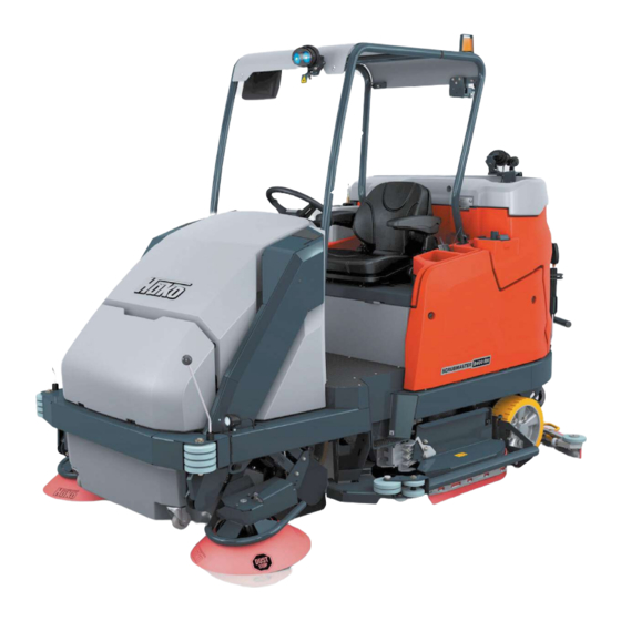
- Page 1 Scrubmaster B400 R / RM / RH (7190) Operating manual Part number 88-10-3255 - Valid as from: 03.2021...
-
Page 2: Introduction
We have provided the points in this operating manual concerning your safety with danger pictograms. Your authorised Hako dealer is available at all times to answer further questions about the vehicle or the operating manual. -
Page 3: Intended Use
Intended use also includes compliance with the operating, maintenance and repair conditions specified by the manufacturer in this operating manual. The Scrubmaster B400 R may be used, maintained and repaired only by per- sons who are familiar with this work and have been briefed and instructed about the dangers. -
Page 4: Acceptance Of The Machine
You will be compensated for transport damage provided you immediately have the damage confirmed by the transport company and send in the damage re- port together with the consignment note to your Hako dealer: Machine data Your machine is described clearly by the following data. Please always quote these data in correspondence or when making a telephone query to your authorised Hako dealer or our company. -
Page 5: Table Of Contents
2.4.1 Solution tank ..............67 2.4.2 Rotating brush unit ............67 2.4.3 Squeegee ..............68 2.4.4 Waste water tank ............68 2.4.5 Side wiper ..............69 2.4.6 Suction turbines ............69 2.4.7 Travel drive ..............69 Scrubmaster B400 R (7190) - Page 6 Changing the battery ..........116 5.2.5 Battery plug coding ............. 119 5.2.6 Maintaining drive batteries .......... 120 5.2.7 Taking the machine out of service for a long period ... 120 5.2.8 Disposing of batteries ..........120 Scrubmaster B400 R (7190)
- Page 7 5.12 Side wiper ..............151 5.12.1 Changing the wiper rubber ......... 151 Attachments/options..........152 Light refuse collector (B400 R only) ......152 Broom strip (B400 R only) .......... 152 Mop strip (B400 R only) ..........152 Scrubmaster B400 R (7190)
- Page 8 Spray suction tool ............153 Manual suction tool ............. 155 Spray nozzle ............... 156 Battery changing system ..........157 Overhead guard ............162 BlueSpot ..............163 6.10 Reversing camera ............164 6.11 StVZO ................. 164 6.12 High-pressure cleaner ..........166 Scrubmaster B400 R (7190)
- Page 9 Scrubmaster B400 R (7190)
-
Page 10: Safety Instructions
Environmental danger Environmental danger due to the use of substances from which a health and environmental risk proceeds. Note Indication of information that facilitates more effective and economical use of the machine. Scrubmaster B400 R (7190) -
Page 11: Staff Qualification
In addition, specialists are familiar with the safety equipment and instructions and are responsible for the initial instruction of the operating staff. Scrubmaster B400 R (7190) -
Page 12: Protective Equipment
Safety shoes protect the feet from heavy falling parts and prevent slipping on slippery surfaces. Protective gloves Protective gloves against mechanical abrasion protect the hands against injuries such as cuts, abrasions, etc. Defective or worn protective gloves must be disposed of in an environmentally friendly manner. Scrubmaster B400 R (7190) -
Page 13: General Safety Instructions
Renew labels that are no longer legible or present. • Only wheels (wheel tyres) approved by Hako may be used. • With Hako-AntiBac® machine variants, silver ions are contained in the plastic of the tank on the inside as well as in the flex wall. -
Page 14: Operating Safety Instructions
• For reasons of safety, the driver's seat is equipped with a seat contact switch. The machine can only be started when the driver is sitting on the driver's seat. The function of the seat contact switch must not be bypassed. Scrubmaster B400 R (7190) -
Page 15: Before Putting Into Service
Please observe the operating manual of the charger and the operating manual of the battery manufac- turer. Hako assumes no liability for battery damage resulting from insuffi- cient commissioning charge. • Check proper condition and operating safety of the machine before every start-up! Do not use the machine as long as there are defects. - Page 16 • When raising and lowering the dirt hopper, there is a risk of crushing or shearing for nearby persons. Ensure a sufficient safety distance. When raising and lowering the dirt hopper, there must be no persons, animals or objects in the work area. Scrubmaster B400 R (7190)
-
Page 17: After Operation
1.5.4 After operation • Turn off the machine and remove the key when leaving the machine to prevent unauthorised use. • After use, park the machine in a dry, indoor location with the working units raised. Scrubmaster B400 R (7190) -
Page 18: Maintenance Instructions
• Do not perform any welding, drilling, sawing or grinding work on parts of the frame. Have damaged parts replaced by a Hako service workshop. • When transporting the machine, the machine must be shut down and properly lashed down. - Page 19 • Risk of crushing while the battery is moving. Do not stay in the battery changing rack while the battery is moving! • Change the battery only on level ground, never on sloping or uneven ground. Scrubmaster B400 R (7190)
- Page 20 • Do not use high-pressure cleaners for cleaning electrical/electronic compo- nents or the machine. • In winter and if there is a risk of frost, drain the water completely from the high-pressure cleaner. Scrubmaster B400 R (7190)
-
Page 21: Information About Special Risks
• Make sure the batteries are never fully discharged; recharge them as quickly as possible. • Only batteries approved by Hako may be used at the intended position. • Danger! Make sure that the insulation of the battery cables is not damaged. -
Page 22: Hydraulic System (B400 Rh Only)
Do not place the battery plug on the battery during charging! Never place tools or other electrically conductive objects on the battery! • For further safety instructions, see Hako supplementary sheet 88-60-2556 – information for drive batteries. • Only refill distilled water. -
Page 23: Environmental Protection Instructions And Disposal
Return and recycling have to be arranged with the authorised Hako dealer as required in § 6 and § 8 of the German battery law (BattG)! •... -
Page 24: Labels On The Machine
Safety instructions Labels on the machine The following safety and instruction labels are affixed to the machine in a clearly visible and legible manner. Renew missing or illegible labels immediately! Fig. 1 Scrubmaster B400 R (7190) - Page 25 Label: Company logo Fig. 1-A / Fig. 2-A The Hako company logo is located at the front on the cover (B400 R) or on the hood (B400 RM/RH) and at the rear on the cap of the flex wall tank.
- Page 26 Safety instructions Fig. 2 Scrubmaster B400 R (7190)
- Page 27 The label is located on the right side of the seat console underneath the driver's seat. Label: 36 V Fig. 2-Q The label is located on the right side of the seat console underneath the driver's seat. Scrubmaster B400 R (7190)
-
Page 28: Use
2 Use Overviews The description in chapter 2 contains information on the function and handling of the individual controls on the machine. 2.1.1 Front view (B400 R) Fig. 3 Scrubmaster B400 R (7190) - Page 29 Key for side panelling/side door Fresh water filling opening Drinks holder, storage compartment and socket for USB connection Side panelling Ball cock Fresh water filter Rotating brush unit Brake button Quick-Connect for light refuse collector, broom strip, mop strip (option) Scrubmaster B400 R (7190)
-
Page 30: Front View (B400 Rm)
2.1.2 Front view (B400 RM) Fig. 4 Scrubmaster B400 R (7190) - Page 31 Fresh water filter Rotating brush unit Pre-sweep suction unit Side broom with optional Dust Stop Start rollers Drive-up aid for ramps Bracket for dirt hopper locking device Dirt hopper Dip stick Pre-sweep suction unit hood Brake button Scrubmaster B400 R (7190)
-
Page 32: Front View (B400 Rh)
2.1.3 Front view (B400 RH) Fig. 5 Scrubmaster B400 R (7190) - Page 33 Pre-sweep suction unit Side broom with optional Dust Stop Working light (option) / StVZO lighting (option) Start rollers Drive-up aid for ramps High dump dirt hopper Dip stick Coarse material flap Pre-sweep suction unit hood Overhead guard (option) Scrubmaster B400 R (7190)
-
Page 34: Rear View
2.1.4 Rear view Fig. 6 Scrubmaster B400 R (7190) - Page 35 Folding step with solution tank maintenance opening behind it Fresh water drain hose Water treatment / high-pressure cleaner (option) Suction hose Working light, reversing camera with monitor (option) BlueSpot (option) Flex wall tank cap Battery plug Battery Waste water tank Intake sieve Scrubmaster B400 R (7190)
-
Page 36: Control Panel
Button Fresh water supply Switch Hazard warning system (option) Button Tool operation (option) Button Brush unit Button Squeegee Button High dump unlocking device (B400 RH only) Button Boost function Button Speed reduction forwards gear Button Clean On Scrubmaster B400 R (7190) - Page 37 Button Lower dirt hopper (B400 RH only) Button Raise dirt hopper (B400 RH only) Button Suction fan / Filter cleaning (B400 RM/RH only) Button Signal horn Button Pre-sweep suction unit (B400 RM/RH only) I-Button Reader (option) Scrubmaster B400 R (7190)
-
Page 38: Controls And Display Elements
If the machine does not have a particular tool, it is excluded from the switching order. • Press the button: Spray nozzle ON • Press the button twice: Manual suction and spray suction tool ON • Press the button again: Tool operation OFF Scrubmaster B400 R (7190) - Page 39 • Press the button: The squeegee is lowered and the suction turbines are switched on. • Press the button again: After approx. 15 seconds of after-run time, the squeegee is raised and the suction turbines are switched off. Scrubmaster B400 R (7190)
- Page 40 • Press and hold the button: the highest level of fresh water dosing and the increased brush pressure are activated simultaneously. • Release the button: the machine switches back to the operating mode it was in before the boost function. Scrubmaster B400 R (7190)
- Page 41 (B400 RM/RH) are switched off. The squeegee and the suction turbines continue to run for approx. 15 seconds to absorb residual water. The squeegee is then raised and the suction turbines are switched off. Scrubmaster B400 R (7190)
- Page 42 Steering column switch Fig. 7-14 (option) The lighting system and the turn indicators are switched on and off with this button. More information on the individual functions, see section 6.11 StVZO on page 164. Scrubmaster B400 R (7190)
- Page 43 To do this, the High dump unlocking device button Fig. 7-9 must additionally be pressed. • Press the button: Swivel/Empty the dirt hopper • Release the button: Dirt hopper movement stops Scrubmaster B400 R (7190)
- Page 44 The dirt hopper is raised with this button. To do this, the High dump unlocking device button Fig. 7-9 must additionally be pressed. • Press the button: Raise the dirt hopper • Release the button: Dirt hopper movement stops Scrubmaster B400 R (7190)
- Page 45 Signal horn button Fig. 7-21 The signal horn is switched on with this button. • Press the button: Signal horn ON • Release the button: Signal horn OFF Scrubmaster B400 R (7190)
- Page 46 I-Button. • Press the I-Button for approx. 2 seconds against the I-Button Reader. • The red LED goes out. The machine is ready for operation. Scrubmaster B400 R (7190)
-
Page 47: Multifunction Display
Fig. 8-1 appears. By selecting and confirming the soft key Menu selection Fig. 8-5 you access the sub-menu Fig. 8-4. Note It is only possible to switch to the sub-menu if the cleaning functions are switched off! Scrubmaster B400 R (7190) -
Page 48: Menu Guidance
You can jump back to the previous menu using the return button Fig. 8-2. 2.3.2 Main menu Fig. 9 The main menu is divided up into three levels. • Status level Fig. 9-1 • Function level Fig. 9-2 • Action level Fig. 9-3 Scrubmaster B400 R (7190) - Page 49 User The symbol indicates the currently set user profile. Silent operation The symbol appears when the machine is working in reduced-noise operation. The symbol also appears at the Squeegee symbol. Scrubmaster B400 R (7190)
- Page 50 The symbol appears if a service case occurs. An acoustic warning is also output and a four-digit ser- vice code appears on the right next to the symbol, see section 3.6 Service information on page 97. Scrubmaster B400 R (7190)
- Page 51 Squeegee and suction turbines active. Manual suction/ Manual suction tool or spray suction tool active spray suction tool (options). The suction for the spray suction tool can be deactivated by pressing the Squeegee button. Spray nozzle Spray nozzle active (option). Scrubmaster B400 R (7190)
- Page 52 5.4.1 Emptying the waste water tank on page 125. Battery charging The current charge level of the battery is displayed in state indicator steps of 10 %, see section 5.2.1 Checking the charging state on page 111. Scrubmaster B400 R (7190)
- Page 53 Example: Lower dirt hopper function locked. Function If a symbol with a white arrow appears, a dirt hopper symbol with movement is carried out. white arrow Example: Lower the dirt hopper. (B400 RH only) Scrubmaster B400 R (7190)
- Page 54 An action window Fig. 10-10 opens, in which the settings can be carried out using the turn-push knob. The action windows close automatically after a few seconds or by pressing the return key. Scrubmaster B400 R (7190)
- Page 55 (option) If the working light is switched on, the colour of the soft key changes from white to green. • Rear working lights are on when reverse direction button Fig. 7-13 is activated. Scrubmaster B400 R (7190)
- Page 56 • The function is enabled or locked – depending on the lock symbol • High dump not in motion Tilt / straighten dirt hopper • The function is enabled or locked – depending on the lock symbol • Dirt hopper not in motion Scrubmaster B400 R (7190)
-
Page 57: Sub-Menu
After calling up the sub-menu, the cursor automatically jumps to the operating hours menu. To return to the main menu, press • the soft key Home Fig. 11-1 or • the return button Fig. 11-8 on the control panel. Scrubmaster B400 R (7190) - Page 58 Example: Cleaning the fresh water filter. When this menu is exited, a floppy disk appears. By selecting and pressing the Floppy disk sym- bol, you are confirming that you have carried out the maintenance. Speed-dependent water dosing ON/OFF Scrubmaster B400 R (7190)
- Page 59 • Activating/Deactivating water treatment (option). • Calling up the first page of the Maintenance menu. • Silent function ON/OFF The suction turbine is switched to silent mode, which results in slightly reduced suction power. • Water treatment (option) ON/OFF. Scrubmaster B400 R (7190)
- Page 60 Three programs (A, B, C) with user-specific set- tings can be stored in the Setting menu. The modification of user profiles requires addi- tional access rights. This access authorisation is only intended for Hako service engineers. Scrubmaster B400 R (7190)
- Page 61 Configuration menu Fig. 11-6 Making changes to the configuration menu requires additional access rights (4-digit numer- ical code). This access authorisation is only intended for Hako service engineers. The following settings are made in the configu- ration menu: • Activate/deactivate options.
-
Page 62: Controls At The Machine
2.3.4 Controls at the machine Fig. 12 Side door Accelerator pedal Waste water tank maintenance opening Waste water tank drain hose Maintenance opening solution tank Scrubmaster B400 R (7190) - Page 63 The cleaning opening is used for cleaning the waste water tank. Drain hose for waste water Fig. 12-4 The waste water tank is drained using the drain hose. Solution tank maintenance opening Fig. 12-5 The maintenance opening is used for cleaning the solution tank. Scrubmaster B400 R (7190)
- Page 64 Fig. 13 Fresh water filling opening Fresh water drain hose Ball cock Fresh water filter Brake button Bracket for dirt hopper locking device (B400 RM only) Coarse material flap (B400 RH only) Side panelling Scrubmaster B400 R (7190)
- Page 65 Reach into the central recessed grip on the front cover and open the coarse material flap in the driving direction. Side panelling Fig. 13-8 The suction turbines and the electronics are located behind the side panelling. The side panelling can be easily removed using the provided wrench. Scrubmaster B400 R (7190)
-
Page 66: Functional Description
Functional description Scrubmaster B400 R is a ride-on scrubber-drier for wet cleaning hard floor surfaces. In cleaning mode, the cleaning solution is supplied from the solution tank to the rotating brushes in the brush unit. As the machine moves forward, waste... -
Page 67: Solution Tank
The brushes in the rotating brush unit can be decoupled for maintenance pur- poses by pressing the soft key Decouple rotating brushes Fig. 10-4 on the multifunction display, see section 5.6.3 Decoupling the rotating brushes/pads on page 133. Scrubmaster B400 R (7190) -
Page 68: Squeegee
In this case, a warning symbol illuminates on the multifunction display. An acoustic warning is output at the same time. Scrubmaster B400 R (7190) -
Page 69: Side Wiper
X-AC drive (option) The X-AC drive is an electrical machine with a gearbox on the rear axle which acts as a drive and deceleration aid for the travel drive on the front axle. Scrubmaster B400 R (7190) -
Page 70: Brakes
Attention When using other batteries which have been approved by Hako, the BMS must be reset to protect the battery against total discharge. The settings of the BMS must only be carried out by a Hako service workshop! For more information, see section 5.2 Battery on page 111. -
Page 71: Side Broom (B400 Rm/Rh Only)
The agitator is started automatically after the sweep- ing function or the suction fan has been switched off. If dust is generated while working with the machine, stop sweeping and activate filter cleaning via the Fig. 7-20 button. Scrubmaster B400 R (7190) -
Page 72: High-Pressure Cleaner (Option)
Fig. 9. Information on the function and operation of the high-pressure cleaner, see section 6.12 High-pressure cleaner on page 166. 2.4.15 Steering column switch StVZO (option) Fig. 18 Steering column switch Quick release steering wheel height adjustment Scrubmaster B400 R (7190) -
Page 73: Working Light, Reversing Camera With Monitor And Flashlight (Option)
The flashlight Fig. 19-4 is mounted on the machine in such a way that it is clearly visible from all sides. If there is no overhead guard (option), the flash- light is located on the cap of the water tank. The flashlight is switched on and off via the multifunction display. Scrubmaster B400 R (7190) -
Page 74: Operation
• Risk of the servo drive overheating. Do not press the steering wheel against the end stop for too long. The power steering could overheat and as a result the steering could become much more sluggish. Scrubmaster B400 R (7190) -
Page 75: Instruction
Operation Instruction Instruction is required before the first start-up. The first-time instruction of the machine must be provided only by a specialist of your authorised Hako dealer. Before putting into service Warning • Check proper condition and operating safety of the machine before every start-up! Do not use the machine as long as there are defects. -
Page 76: Check List: Before Machine Start-Up
5.11.2 13 If necessary, install the sweeping roller. 5.8.4 14 Empty the waste water tank and clean it as required. 5.4.1 5.4.2 15 Fill the solution tank and add detergent according to the 5.3.1 manufacturer's specifications. Scrubmaster B400 R (7190) -
Page 77: Checking The Working Light, Flashlight And Warning Device (Option)
Action level on page 54. 3. Turn the machine off with the key switch. Note If one of the lights or warning devices does not work, contact your Hako service workshop! Scrubmaster B400 R (7190) -
Page 78: Checking The Lighting System And Horn (Option)
6.11 StVZO on page 164. 3. Turn the machine off with the key switch. Note If one of the lights or the horn does not work, contact your Hako service workshop! 3.3.3 Driver's seat Danger •... - Page 79 • Drivers who weigh more turn the handwheel to the right. Adjusting the tilt of the armrests Adjust the tilt of the armrests by turning the wheel Fig. 21-4. The armrests can be folded up when not in use. Scrubmaster B400 R (7190)
-
Page 80: Steering Wheel Height Adjustment (Option)
Move the steering column switch Fig. 22-3 to the position shown. 5. Close the quick release again. 6. Make sure that the steering wheel can no longer be moved up and down, readjust the quick release if necessary. Scrubmaster B400 R (7190) -
Page 81: Side Mirror (Option) Adjustment
• Never adjust the side mirror while driving. Risk of accident! • Only adjust the side mirror if the machine is stationary. Fig. 23 Adjust the outside mirrors on the overhead guard Fig. 23-1 so that a full view of the rear working area is provided. Scrubmaster B400 R (7190) -
Page 82: Cleaning
• Danger of tilting over when driving on excessively steep slopes Cleaning on slopes of up to 6 % (standard drive) or 15 % (X-AC drive) must only take place for a limited period of time and with special caution. Scrubmaster B400 R (7190) - Page 83 7. In the event of heavy soiling, increase the brush pressure using the soft key Brush pressure on the multifunction display or press the Boost function but- ton Fig. 24-5 (increased cleaning power for 1 minute). Scrubmaster B400 R (7190)
-
Page 84: Entry.x (Option)
Function of the working tools is locked, transport is possible Note A red illuminated LED is a request for activation of the operating data recording system via the I-Button! Ending operation Turn the machine off with the key switch. Scrubmaster B400 R (7190) -
Page 85: On-Board Dosing System (Option)
When the program is started, the detergent is conveyed to the brush unit by means of the dosing pump. The program finishes automatically. The on-board dosing system is ready for operation. Scrubmaster B400 R (7190) - Page 86 Set the desired mixing ratio Fig. 27-2 and confirm with the turn-push knob. The set mixing ratio is displayed with a green background Fig. 27-3. Change: Set the desired mixing ratio. The value is accepted automatically. Turn off: Press the turn-push knob. Scrubmaster B400 R (7190)
-
Page 87: Useful Cleaning Tips
Useful cleaning tips Before starting wet cleaning, it is necessary to sweep the floor (basic version of the Scrubmaster B400 R). This not only enhances the cleaning effect but also reduces wear of the machine's working tools. If the floors are really dirty or wax needs to be removed, treat the floor twice. -
Page 88: Handling And Braking The Vehicle
Overload protection In case of an overload, e.g. excessively steep slopes, the drive motor is switched off after a certain period of time. • Let the machine cool down for approx. 15 minutes. • Restart the machine. Scrubmaster B400 R (7190) -
Page 89: Towing The Machine
Only tow the machine with a towbar! If the machine stops on an uphill or downhill gradient, call the towing service or a Hako service workshop! Attention Before towing, the brakes must be unlocked. Releasing the parking brake on machines with a charged battery Fig. - Page 90 If the machine’s battery is deeply discharged or missing, the parking brake must be unlocked by means of a voltage source. A power bank (customer service kit 97501225) with a suitable connection cable is available from the Hako spare parts service for this purpose. The following steps must be carried out: 1.
- Page 91 The machine can no longer be driven! Restart the rear wheel brake in reverse order. Note With an X-AC drive (option), the rear axle brake locking lever must be swivelled back to its original position. The machine is secured against rolling away. Scrubmaster B400 R (7190)
- Page 92 B400 R. In this case, the attachment point Fig. 31-2 is used. 1. Install the front towing coupling Fig. 31-1 or the rear towing eye Fig. 31-4 from the customer service kit 97501125 (available from the Hako spare parts service) as specified.
-
Page 93: Turning Off The Machine
When the machine is at standstill, the parking brake is activated automatically. 2. Switch off the cleaning functions. 3. Turn off the machine with the key switch. Note Remove the key when leaving the machine to prevent unauthorised use. Scrubmaster B400 R (7190) -
Page 94: Check List: After Cleaning
Check the sealing strips and suction hose. Check the functions and settings. Charge the battery. 5.2.2 10 Clean the machine. If the machine is not used the next day, 5.3.2 the solution tank must be fully emptied. Scrubmaster B400 R (7190) -
Page 95: Loading And Transporting
When loading the machine, observe its weight, see section 4 Technical data on page 100. Fig. 32 Main attachment point B400 R/RM/RH Main attachment point support B400 RM/RH Attachment points on the rear of the machine B400 R/RM/RH Scrubmaster B400 R (7190) - Page 96 To do this, securely lash the machine at both sides in the middle Fig. 32-1 and the rear Fig. 32-3 with tension straps. In addition, lash the machine on both sides at the supporting attachment points Fig. 32-2 with tension straps. Scrubmaster B400 R (7190)
-
Page 97: Service Information
(tool key). The table below explains the most important service codes. If the cause cannot be eliminated and for all service codes not listed here, notify your authorised Hako dealer or your Hako service workshop. - Page 98 Cleaning function Drive wheel becomes slug- Remove foreign 3.4.5.2 switches off gish due to foreign particles particles Drive motor overheats Let the engine cool down 3.6.6.4 Driving and cleaning Seat permanently loaded Relieve seat not possible Scrubmaster B400 R (7190)
- Page 99 Install correct battery installed 7.1.5.1 USB connection not Connected consumer Check whether the working overloaded consumer is drawing too much power or there is a short-circuit in the connected cable Internal controller defect Notify Hako service workshop Scrubmaster B400 R (7190)
-
Page 100: Technical Data
Weight when empty (without batteries, water, driver, dirt and options) Rotating brush 1550: 1130 Weight with batteries (without water, driver, dirt and options) Rotating brush 1550: 1730 1900 2040 Permissible total weight (without options) 2210 2440 2610 Scrubmaster B400 R (7190) - Page 101 3-rotating brush unit 1550 2280 3020 Wheels Name Unit B400 R B400 RM B400 RH Wheel diameter front/rear Specific wheel contact (ready for operation N/mm with driver): front 0.84 1.15 1.16 rear 0.80 0.82 0.77 Scrubmaster B400 R (7190)
- Page 102 9,800 - Standard 11,100 11,100 - X-AC Rotating brush 1550 14,000 12,400 - Standard 14,000 14,000 - X-AC Vacuum system Name Unit B400 R B400 RM B400 RH Air quantity suction turbines (maximum) Vacuum (maximum) mbar Scrubmaster B400 R (7190)
- Page 103 Power consumption vacuum motor (P1) Suction turbines: Power consumption brush motor (P1) 3-rotating brush unit 1230 3-rotating brush unit 1550 Sweeping roller Side broom Power consumption water pump (P1) Type of protection IPX 3 Protection class Scrubmaster B400 R (7190)
- Page 104 Rotating brush 1230 Rotating brush 1550 Side broom speed Gross dirt hopper volume Litre (2x44) Maximum dirt weight (2x50) Lift height of dirt hopper 1660 Filter area m² Filter dust class (IEC 60335-2-69) M / H optional Scrubmaster B400 R (7190)
- Page 105 DIN EN ISO 5349 is: < 2.5 Under the customary conditions of use, the weighted effective value of the acceleration to which the body (feet or seat surface) is subjected to DIN EN ISO 2631-1 is: < 2.5 Scrubmaster B400 R (7190)
-
Page 106: Maintenance And Servicing
• Only put the machine into service when all the protective devices are attached and in protection position. • Do not perform any welding, drilling, sawing or grinding work on parts of the frame. Have damaged parts replaced by a Hako service workshop. Attention •... - Page 107 Daily and weekly maintenance work can be performed by an operator trained for this purpose. For all other maintenance work, see the service booklet, please contact your nearest Hako service workshop or your authorised Hako dealer. Any warranty claim is null and void if this is not complied with and damage results.
-
Page 108: Maintenance Plan
• Empty the dirt hopper and clean if necessary. • Clean the sweeping roller and the sweeping roller 5.8.2 compartment. • Check the dirt hopper seals and clean if necessary. • Visually inspect the V-belt of the sweeping roller. Scrubmaster B400 R (7190) - Page 109 • Pre-sweep suction unit especially for high dump (B400 RH only) • Visually inspect hoses, couplings and connecting elements for leaks. • Visually inspect the hydraulic cylinder. • Check the hydraulic oil level, top up if necessary. Scrubmaster B400 R (7190)
- Page 110 • Check the hydraulic oil level, top up if necessary. If the hydraulic oil level is below the min mark or if leaks are detected, inform the Hako service workshop. • High-pressure cleaner (option) Visually inspect hoses, couplings and connecting elements for leaks.
-
Page 111: Battery
Only travel at half speed is possible. Battery must be fully charged immediately! BMS service infor- Service information, see section 3.6 mation. A four-digit Service information on page 97. service code appears at the same time Fig. 33-1. Scrubmaster B400 R (7190) -
Page 112: Charging The Battery
• Before initially starting up the machine, the battery that is used must be fully and properly charged with commissioning charge. Please observe the operating manual of the charger and the operating manual of the battery manufacturer. Hako assumes no liability for battery damage resulting from insufficient commis- sioning charge. - Page 113 Fig. 34-1. The batteries should be charged if the battery capacity is less than 60 %. Note For safe charging, the Hako charger and the battery have a safety circuit (pilot contact control unit). The charger (99746410) can only charge batteries that have the PCCU circuit Fig.
- Page 114 • Turn off the charger and wait approx. 15 minutes with the seat console open. • Remove the charger plug from the battery socket. Plug the machine plug Fig. 34-4 back into the battery socket Fig. 34-3. Scrubmaster B400 R (7190)
-
Page 115: Checking The Acid Level
• Observe the information in the operating manual of the battery manufacturer! • Refilling must only take place once the battery charging process has been terminated. Note Batteries approved by Hako are equipped with an aquamatic system. Fig. 35 Float indicator Aquamatic system... -
Page 116: Changing The Battery
Maintenance and servicing 5.2.4 Changing the battery Warning • Only use batteries approved by Hako at the intended position! • The battery should only be changed by trained operating staff! • Wear safety shoes and protective gloves when changing the battery. - Page 117 10.To fit the battery, follow the instructions in the reverse order. Note Please ensure that the battery trough is in the correct installation position! See connecting diagram Fig. 36-2. Note Information on handling the battery changing system, see section 6.7 Battery changing system on page 157. Scrubmaster B400 R (7190)
- Page 118 5. Tighten the clamp bolts to a tightening torque of 25 Nm. 6. Remove the two fitted screws Fig. 37-3 on the clamp. 7. Install the battery socket on the clamp using the two screws. The tightening torque is 5 Nm. Scrubmaster B400 R (7190)
-
Page 119: Battery Plug Coding
Machine plug Coding pin Charger plug When using other batteries which have been approved by Hako, the plugs must be re-coded. The battery socket Fig. 38-1, the machine plug Fig. 38-2 and the charger plug Fig. 38-4 are coded with coloured coding pins (yellow, grey or green) Fig. -
Page 120: Maintaining Drive Batteries
Maintenance and servicing 5.2.6 Maintaining drive batteries For maintaining and servicing drive batteries, see Hako supplementary sheet 88-60-2556 – Information for drive batteries and the operating manual of the bat- tery manufacturer. 5.2.7 Taking the machine out of service for a long period If the battery is not used for more than three months, the battery must be recharged. -
Page 121: Filling The Solution Tank
4. Add detergent according to the manufacturer’s regulations (observe table above). 5. Fill the solution tank with fresh water up to the maximum filling level. 6. Close the cap and snap it into place with a little hand pressure. Scrubmaster B400 R (7190) - Page 122 6. Close the water supply and remove the hose with the quick coupling. 7. Close the cap and snap it into place with a little hand pressure. Note In addition to automatic filling, the machine can also be filled manually through an additional opening Fig. 41-4. Scrubmaster B400 R (7190)
-
Page 123: Emptying The Solution Tank
1. Drive to a suitable disposal centre. 2. Park the machine, ensuring the drain hose Fig. 42-1 reaches the drain in the ground. 3. Turn the machine off and remove the key. 4. Remove the drain hose from the holder. Scrubmaster B400 R (7190) -
Page 124: Cleaning The Solution Tank
3. Check the seal and replace if necessary. 4. Grease the seal with suitable grease, e.g. Molykote. 5. Ensure that the drain hose closure is fully closed! 6. Stow away the drain hose correctly in the holder again Fig. 42-7. Scrubmaster B400 R (7190) -
Page 125: Waste Water Tank
4. Remove the drain hose Fig. 44-2 from the holder, open the drain valve and empty the waste water tank over the drain. 5. Ensure that the drain hose closure is fully closed after draining Fig. 44-3! 6. Stow away the drain hose in the holder again. Scrubmaster B400 R (7190) -
Page 126: Cleaning The Waste Water Tank
Clean the waste water tank as required but at least once a day. Fig. 45 Step Top filter tube guide Cap support Bottom filter tube guide Drain hose quick release Waste water tank drain hose Waste water tank Filter tube Coarse dirt sieve Coarse dirt sieve holder Scrubmaster B400 R (7190) -
Page 127: Cleaning The Coarse Dirt Sieve
2. Remove the coarse dirt sieve Fig. 45-9 upwards, tip it out, clean it with water and reinsert it. 3. Open the cap of the flex wall tank as far as it will go. This unlocks the tank support Fig. 45-3 and the tank cap can be closed. Scrubmaster B400 R (7190) -
Page 128: Cleaning The Intake Sieve
Check the function of the seal at the drain valve Fig. 47-1 daily, replace it after 125 operating hours at the latest. 1. Twist drain valve by 90° and swivel down from drain hose. 2. Change the seal. 3. Grease the seal and cone with suitable grease, e.g. Molykote. Scrubmaster B400 R (7190) -
Page 129: Cleaning And Checking The Seal In The Tank Cap
Cleaning and checking the seal in the tank cap Fig. 48 Clean the seal Fig. 48-1 in the tank cap daily and check it for proper function- ing. In case of damage, have it replaced by a Hako service workshop. Scrubmaster B400 R (7190) -
Page 130: Cleaning The Fresh Water Filter
Check the filter sieve Fig. 49-6 of the fresh water filter Fig. 49-1 weekly and clean or replace it as required. Fig. 49 Fresh water filter Ball cock Side collision protection (option) Side wiper Filter cap Filter sieve Scrubmaster B400 R (7190) - Page 131 Insert the filter sieve into the filter cap and screw in the filter cap clockwise hand-tight. 7. Open the ball cock. 8. Swivel back the side wiper and hook it in. 9. If present, swivel back the side collision protection and hook it in. Scrubmaster B400 R (7190)
-
Page 132: Rotating Brush Unit
The rotating brushes/pads Fig. 50-4 must be changed at the latest when the indicator Fig. 50-3 is in the red zone. Note If no rotating brushes/pads are fitted, the top edge of the display plate is outside the coloured area. Scrubmaster B400 R (7190) -
Page 133: Cleaning The Rotating Brushes
5. Raise both side wipers Fig. 49-4 on both sides of the machine and swivel them to the side. 6. Remove the rotating brushes/pads. Scrubmaster B400 R (7190) -
Page 134: Coupling The Rotating Brushes/Pads
7. Check whether the rotating brushes have been coupled. Also pay attention to unusual noises or vibrations. 8. Swivel back both side wipers and hook them in. 9. If present, swivel back the two side collision protection systems and hook them in. Scrubmaster B400 R (7190) -
Page 135: Dirt Hopper (B400 Rm/Rh Only)
3. Use the recessed grips to pull out the dirt hoppers Fig. 53-1. 4. Fold over the carrying handle and empty the dirt hoppers Fig. 53-3. 5. Check the sweeping roller and the sweeping roller compartment Fig. 53-4 and clean if necessary. Installation is in reverse order. Scrubmaster B400 R (7190) -
Page 136: Emptying The Dirt Hopper (B400 Rh)
Empty the dirt hopper at regular intervals. Fig. 54 Button Unlock high dump Button Raise dirt hopper Button Empty dirt hopper Button Straighten dirt hopper Button Lower dirt hopper Dirt hopper raised End position Empty dirt hopper Scrubmaster B400 R (7190) - Page 137 10.Lower the dirt hopper. To do this, press and hold the two buttons Unlock high dump Fig. 54-1 and Lower dirt hopper Fig. 54-5 on the control panel simultaneously until the end position has been reached. Scrubmaster B400 R (7190)
-
Page 138: Pre-Sweep Suction Unit (B400 Rm/Rh Only)
2. If necessary, remove straps and other packaging materials from the sweeping roller. 3. Thoroughly clean the sweeping roller under running water. 4. Clean the sweeping roller compartment. 5. Insert the sweeping roller, see section 5.8.4. Scrubmaster B400 R (7190) -
Page 139: Removing The Sweeping Roller
Fig. 55-1. 5. Unscrew the two black star-shaped handles with the yellow dots Fig. 55-5 and remove the plate with seal Fig. 55-6. 6. Pull out the sweeping roller Fig. 55-4. Scrubmaster B400 R (7190) -
Page 140: Inserting The Sweeping Roller
Fig. 55-5. 4. Fit the cover Fig. 55-1 onto the sweeping roller and install it with the yellow star-shaped handle Fig. 55-2. 5. Adjust the sweeping level, see section 5.8.5. Scrubmaster B400 R (7190) -
Page 141: Adjusting The Sweeping Level
• If the sweeping level is incorrect, proceed with the other steps. 6. Turn the machine off and remove the key. 7. Adjust the sweeping level with the star-shaped handle Fig. 56-2. 8. Repeat the process until the adjustment is correct. Scrubmaster B400 R (7190) -
Page 142: Side Broom (B400 Rm/Rh Only)
4. Remove the side broom Fig. 57-3 downwards. 5. Fit the new side broom onto the hub Fig. 57-4. 6. Insert the locking pin underneath the broom into the hole in the hub and lock it. Scrubmaster B400 R (7190) -
Page 143: Adjusting The Side Broom
Compared to a clock lying on the floor, where the 12 is at the front in driving direction, the sweeping level Fig. 58-3 must be marked on the floor from 9 to 3 o’clock. 7. Repeat the process until the adjustment is correct. Scrubmaster B400 R (7190) -
Page 144: Filter System/Dust Extraction System (B400 Rm/Rh Only)
Clean the plate filter multiple times per day using the agitator. To clean the filter during operation, press the Suction fan/Filter cleaning but- ton. The suction fan is switched off and several agitating intervals follow. Scrubmaster B400 R (7190) -
Page 145: Basic Cleaning Of The Plate Filter
Do not inhale the dust! Wear a suitable dust mask. Fig. 59 Unlocking device of pre-sweep suction unit hood (B400 RM) Unlocking device of pre-sweep suction unit hood (B400 RH) Plate filter Star-shaped handles Filter hood Mounting plate Scrubmaster B400 R (7190) - Page 146 10.If necessary, carry out this process several times. 11.The plate filter is installed in the reverse order. Attention Please ensure that the plate filter is in the correct installation position! Markings can be found on the frame of the plate filter. Scrubmaster B400 R (7190)
-
Page 147: Squeegee
Fig. 60-3. 5. Remove coarse dirt and clean the squeegee thoroughly using water. Check sealing strips for damage and replace if necessary. 6. Swivel the squeegee back and let it engage in its starting position. Scrubmaster B400 R (7190) - Page 148 1/2” quick coupling, and to the water tap of the service connection. 6. Open the water tap all the way. Squeegee is cleaned by the internal spray nozzles. 7. After the program has ended, close the water tap and remove the hose. Scrubmaster B400 R (7190)
- Page 149 Attention If the hose is not disconnected from the squeegee after the program has ended, the water may run out of the solution tank! Scrubmaster B400 R (7190)
-
Page 150: Changing The Sealing / Slot Strip
Release and remove the tension strap Fig. 62-4. Replacing the slot strip: Fold over the turnbuckle Fig. 62-6 all the way when releasing so that the tension strap is easier to remove. 4. Remove the slot and sealing strip from the squeegee body. Scrubmaster B400 R (7190) -
Page 151: Side Wiper
4. Loosen the wing nut Fig. 63-2. 5. Remove the tension strap Fig. 63-3. 6. Turn the wiper rubber (can be used 4 times) or replace it. Installation is in reverse order. Scrubmaster B400 R (7190) -
Page 152: Attachments/Options
B400 R and locked. It can be used to push fluff, fine dirt and other dirt in front of the Scrubmaster in order to collect them in a separate place where they can be picked up. Scrubmaster B400 R (7190) -
Page 153: Spray Suction Tool
1. Remove the suction hose Fig. 64-3 from the vacuum system opening. 2. Insert the hose of the tool into the vacuum system opening Fig. 64-2. 3. Connect the hose to the water connection of the machine Fig. 64-4. Scrubmaster B400 R (7190) - Page 154 4. Use the Tool operation button Fig. 64-6 on the control panel to switch the tool on and off. The operator must not be sitting on the seat. Press the button twice: Spray suction tool ON Press the button again: Spray suction tool OFF Scrubmaster B400 R (7190)
-
Page 155: Manual Suction Tool
3. Use the Tool operation button Fig. 65-4 on the control panel to switch the tool on and off. The operator must not be sitting on the seat. Press the button twice: Manual suction tool ON Press the button again: Manual suction tool OFF Scrubmaster B400 R (7190) -
Page 156: Spray Nozzle
Press the button again: Spray nozzle water supply OFF 3. Spray nozzle operation: 4 = Operating handle for switching the water supply with locking mechanism on and off 3 = Adjusting lever for water dosing 2 = Water jet type setting Scrubmaster B400 R (7190) -
Page 157: Battery Changing System
Do not stay in the battery changing rack while the battery is moving! Attention • When using other batteries which have been approved by Hako, the BMS must be reset to protect the battery against total discharge. The settings of the BMS must only be carried out by a Hako service workshop! •... - Page 158 Attachments/options Fig. 67 Scrubmaster B400 R (7190)
- Page 159 10.Raise the battery changing rack using the lift truck to the maximum height of 200 mm. 11.Drive the discharged battery to the charging station and charge it, see section 5.2.2 Charging the battery on page 112. Scrubmaster B400 R (7190)
- Page 160 The automatic locking device of the battery in the machine is closed. 6. Remove the battery changing rack from the machine. 7. Plug the machine plug into the battery socket. 8. Fold back the seat console. 9. Close and lock the right side door. Scrubmaster B400 R (7190)
- Page 161 Automatic locking device of battery in the machine Note In case of damage or deformation as well as non-functioning components, contact your Hako service workshop or Hako customer service. Functional check The foot control for unlocking the battery and the associated locking lever must be checked weekly.
-
Page 162: Overhead Guard
Recess for lifting equipment chain when changing the battery Side mirror (option) The overhead guard Fig. 69-1 is used to protect the driver from falling parts in the high bay warehouse, for example. An optional side mirror Fig. 69-3 is available. Scrubmaster B400 R (7190) -
Page 163: Bluespot
The BlueSpot Fig. 70-1 is a visual warning device. A blue spot projected onto the ground warns people and vehicles of approaching machines. In addition, an acoustic warning can be switched on when reversing, see section Action level on page 54. Scrubmaster B400 R (7190) -
Page 164: Reversing Camera
20 km/h. In other countries, the corresponding national reg- ulations must be complied with. Driving license A class L driving licence is required to drive the Scrubmaster B400 R (self-pro- pelled machine up to 25 km/h). In other countries, the corresponding national regulations must be complied with. - Page 165 In the StVZO version, the brake lights light up when the brake button is pressed or when the driving speed is decelerated with the accelerator pedal. The hazard warning system is switched on and off by the switch on the control panel Fig. 72-3. Scrubmaster B400 R (7190)
-
Page 166: High-Pressure Cleaner
Fig. 73 High-pressure lance with manual control Hose on reel On/Off button Pressure line Supply of high-pressure cleaner from solution tank High-pressure cleaner unit Scrubmaster B400 R (7190) - Page 167 • Turn the machine off, remove the key and disconnect the battery plug when cleaning and maintaining the machine and before replacing parts. Note Continuous operation of the high-pressure cleaner should not exceed a period of 10 minutes. Scrubmaster B400 R (7190)
- Page 168 Troubleshooting No pressure present • Check the spray nozzle in the lance, replace if necessary. • Check all hoses, screw connections and components for leaks. • Inform the Hako service workshop and have the problem eliminated. Scrubmaster B400 R (7190)
- Page 169 23843 Bad Oldesloe, Germany declare in sole responsibility that the following products Scrubmaster B400 R, RM, RH Model: 7190 to which this declaration relates correspond with the relevant basic safety and health requirements of EC Directive 2006/42/EC as well as the requirements according to 2014/30/EC and 2014/53/EC.
- Page 170 Hako GmbH Head Office Hamburger Str. 209-239 23843 Bad Oldesloe Germany Tel. +49 4531 806-0 info@hako.com www.hako.com...
Need help?
Do you have a question about the Scrubmaster B400 R and is the answer not in the manual?
Questions and answers