HAKO Scrubmaster B120 R Operating Manual
Hide thumbs
Also See for Scrubmaster B120 R:
- Service booklet (99 pages) ,
- Operation (2 pages) ,
- Circuit diagrams (10 pages)

Related Manuals for HAKO Scrubmaster B120 R


Summary of Contents for HAKO Scrubmaster B120 R
- Page 1 Cleaning Technology · Municipal Technology Scrubmaster B120 R (7177) Operating Manual Part number 88-10-3105 - 3650-33 Valid as from: 07.2017...
-
Page 2: Introduction
We have provided the places in this operating manual concerning your safety with a danger pictogram. Your authorised Hako dealer is available at all times to answer further questions about the vehicle or the operating manual. - Page 3 Introduction Intended use Scrubmaster B120 R is a scrubber-drier for the wet cleaning of hard indoor floor surfaces. This machine is intended for commercial use, e.g. in shopping centres, swimming pools, shops, airports, schools and hotels. Any use extending beyond this is not intended use. The manufacturer is not liable for any damage resulting from this and the user alone bears the risk.
- Page 4 Machine data Your machine is described clearly by the following data. Please always quote these data in correspondence or when making a telephone query to your authorised Hako dealer or our company. • Machine type •...
-
Page 5: Table Of Contents
Table of contents Introduction..............2 Safety instructions ............8 Warning and danger symbols ......... 8 General safety instructions ..........9 Operating safety instructions ........10 Maintenance instructions ..........11 Information about special risks ........12 Environmental protection instructions and disposal ..14 Labels on the machine .......... - Page 6 Table of contents 3.4.5 Spraying nozzle ............43 3.4.6 Useful cleaning tips ............44 3.4.7 Handling and braking the vehicle ......... 45 3.4.8 Pushing the machine ............ 46 3.4.9 Turning off the machine ..........46 3.4.10 Checklist – after cleaning ..........47 Loading and transporting ..........
- Page 7 Table of contents Wiper ................78 5.7.1 Swinging down the wiper ..........78 5.7.2 Replacing the rubber of the wiper ......... 78 Roller brush unit ............79 5.8.1 Emptying the dirt hopper ..........79 5.8.2 Replacing the brushes ..........79 5.8.3 Cleaning the brushes ............
-
Page 8: Safety Instructions
Safety instructions 1 Safety instructions Warning and danger symbols Important tasks concerning the safety of the operator and machine are named as follows in this operating manual and emphasised by symbols. Danger Indication of a direct danger with high risk, in which death or severe physical injury can occur if it is not avoided. -
Page 9: General Safety Instructions
• The labels attached to the machine provide important information for safe operation. Renew labels that are no longer legible or present. • With Hako-AntiBac® machine variants, the plastic inner surface of the fresh water and waste water tanks contains silver ions in nanoparticle form. -
Page 10: Operating Safety Instructions
Please observe the operating manual of the charger and the operating manual of the battery manufacturer. Hako assumes no liability for battery damage resulting from insufficient commissioning charge. • Check the machine for operating safety before every start-up! Eliminate faults immediately. -
Page 11: Maintenance Instructions
• Daily and weekly maintenance work must be done in accordance with the maintenance plan by the operating staff. In all other maintenance work, please contact your nearest Hako service centre. • The maintenance work and maintenance intervals specified in the operating manual must be complied with. -
Page 12: Information About Special Risks
• Only instructed maintenance personnel must handle and replace batteries. • Only batteries approved by Hako may be used at the intended position. • Danger! Make sure that the insulation of the battery cables is not damaged. - Page 13 • Make sure that no water or liquid can come into contact with live parts of the machine. If water has still entered parts, immediately disconnect the mains plug and have the machine checked by the authorised Hako service. 01-7177-00.fm...
-
Page 14: Environmental Protection Instructions And Disposal
Return and recycling have to be arranged with the authorised Hako dealer as required in § 6 and § 8 of the German battery law (BattG)! -
Page 15: Labels On The Machine
Safety instructions Labels on the machine The following safety and instruction labels are affixed to the machine in a clearly visible and legible manner. Attention Renew missing or illegible labels immediately! Fig. 1: 01-7177-00.fm... - Page 16 Safety instructions Fig. 2: 01-7177-00.fm...
- Page 17 Safety instructions Label – Logo Fig. 1-A The Hako logo is located at the front on the steering column and at the rear on the hopper. Label – Read and observe the operating manual Fig. 1-B1 – Maximum permissible slope 2 % when cleaning Fig. 1-B2 –...
-
Page 18: Operation
Operation 2 Operation Overviews The description in chapter 2 contains information on the function and handling of the individual controls on the machine. The controls always have the same item number in all chapters. Fig. 3: 02-7177-00.fm... -
Page 19: Front View
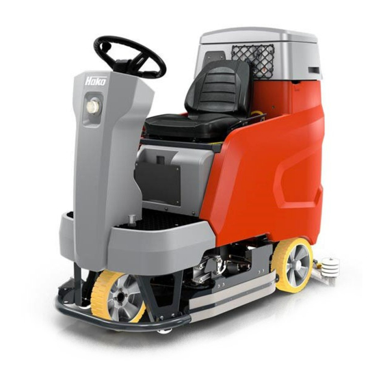
Operation 2.1.1 Front view Item Designation Steering wheel Mains cable on-board charger Driver's seat Tray (option) Manual suction tool or manual spray suction tool (option) Solution tank Brush decoupler rotating brush Rotating brush unit Wiper On-board dosing system (option) Collision protection Working spotlights (option) Operating brake Travel drive... - Page 20 Operation Fig. 4: 02-7177-00.fm...
-
Page 21: Rear View
Operation 2.1.2 Rear view Item Designation Suction filter Waste water tank Coarse dirt sieve (option) Automatic filling unit (option) Filling opening solution tank Cleaning opening solution tank Accelerator pedal Roller brush unit Fresh water filter Ball cock Squeegee Drain hose waste water Suction hose squeegee Maintenance opening solution tank Fresh water level indicator... -
Page 22: Control Panel
Operation Fig. 5: 2.1.3 Control panel Item Designation Display panel Button – brush pressure increase Button – boost function Button – brush unit Button – squeegee Button – fresh water supply Button – fresh water dosing Button – brush unit and squeegee Button –... - Page 23 Operation Key switch I-Button-Reader – Fleet-Recorder Standard (option) Button – speed reduction forwards gear Button – signal horn Button – working spotlights (option) Button – warning device (option) Button – silent operation Button – tool operation (option) 02-7177-00.fm...
-
Page 24: Display Panel
Operation Fig. 6: 2.1.4 Display panel Item Designation Meaning Fresh water dosing The symbol is displayed when the fresh water supply is switched on and the brush unit is lowered. The respective selected level of the water quantity can be read in the display panel. If there are only 10 litres left in the solution tank, the symbol flashes and a warning sound is output. - Page 25 Operation Speed reduction The symbol is displayed when the machine is driving at reduced speed. Parking brake The symbol is displayed when the parking brake is activated. Seat contact The warning symbol lights up if the driver gets up from the driver's seat during operation. Main functions, e.g.
-
Page 26: Controls And Display Elements
Operation Controls and display elements 2.2.1 Control panel The individual functions of the buttons on the control panel are described below. The respective activated functions are visible as corresponding symbols in the display panel. Key switch Fig. 5-43 The electrical system is switched on and off with the key switch. •... - Page 27 Operation Speed reduction button Fig. 5-45 The maximum speed when driving forwards is reduced by approx. 50 % with this button. • Push the button: Speed reduction ON • Push the button again: Speed reduction OFF Signal horn button Fig. 5-46 The signal horn is switched on and off with this button.
- Page 28 Operation Brush unit button Fig. 5-36 The brush unit is lowered and raised with this button. • Push the button: The brush unit is lowered. When actuating the accelerator pedal, the brush drive and the water supply are switched on. •...
- Page 29 Operation Brush unit and squeegee button Fig. 5-40 The brush and suction turbine drive are switched on and off simultaneously with this button. • Push the button: The brush unit and the squeegee are lowered, the suction turbine is switched on. The brush drive and the water supply are switched on when the accelerator pedal is actuated.
- Page 30 Operation On-board dosing system button (option) Fig. 5-41 The dosing system for the detergent is switched on and off with this button. • Push the button: Dosing system ON • Push the button again: Dosing system OFF Warning device button (option) Fig. 5-48 Two functions can be selected with this button: •...
- Page 31 Operation Tool operation button (option) Fig. 5-50 Tool operation is switched on and off with this button when the manual suction or manual spray suction tool is connected. The driver must not be on the driver's seat. • Push the button: Tool operation ON •...
-
Page 32: Controls At The Machine
Operation 2.2.2 Controls at the machine Fig. 7: Mains cable Fig. 7-2 The mains connection supplies voltage to the on-board charger. Operating brake Fig. 7-13 When the accelerator pedal is released, the machine comes to a stop due to the braking effect of the travel drive. If this braking effect is not sufficient, the operating brake can be applied in addition. - Page 33 Operation Fig. 8: Brush decoupler rotating brush Fig. 8-7 By actuating the brush decoupler, the rotating brushes can be disassembled quickly and without tools. Fresh water filter Fig. 8-24 When supplying water from the solution tank to the brush unit, the fresh water is cleaned by the filter insert.
-
Page 34: General Principle Of Operation
Operation General principle of operation Scrubmaster B120 R is a ride-on scrubber-drier for wet cleaning hard floor surfaces. In cleaning mode, the cleaning solution is supplied from the solution tank to the rotating brushes in the brush unit. When the machine is moving forwards, the used waste water is absorbed by the squeegee and conveyed into the waste water tank. -
Page 35: Squeegee
Operation 2.3.3 Squeegee The movable, hinged squeegee Fig. 9-26 is lowered and switched on with the squeegee button Fig. 5-37. The squeegee withdraws the waste water from the floor using a sealing strip. The suction turbine vacuums the waste water from the floor. -
Page 36: Putting Into Service
Instruction Instruction is required before the first start-up. The first-time instruction of the machine must be provided only by a specialist of your authorised Hako dealer. This person will be notified immediately after delivery of the machine from the factory and will contact you to make an instruction appointment. -
Page 37: Checklist - Before Machine Start-Up
Putting into service Checklist – before machine start-up No. Description Checking the parking area for signs of leaks. Cables and tanks must not show any sign of leaks or damage Installing the mains cable, see section 3.3.1 Mounting the brushes and squeegee, see chapter Maintenance Adjusting the driver's seat, if necessary, see section 3.3.2 Checking the battery charge and recharge it as required, see section 5.3 Emptying the waste water tank and clean it as required, see section 5.5... -
Page 38: Driver's Seat
Putting into service 3.3.2 Driver's seat Attention For reasons of safety, the driver's seat is equipped with a seat contact switch. The function of the seat contact switch must not be bypassed. Adjusting the standard driver’s seat Fig. 12: Adjust the driver’s seat with the lever Fig. 12-A so that all the controls can be reached effortlessly. -
Page 39: Cleaning
Putting into service Cleaning Attention • Before operating the machine, read and observe the safety instructions in chapter 1. • The machine can only be put into service when the driver is sitting on the driver's seat. • The travel drive can only be started when the accelerator pedal is not actuated when turning the machine on. -
Page 40: Fleet-Recorder Standard (Option)
Putting into service 3.4.1 Fleet-Recorder Standard (option) The Fleet-Recorder records operating times and further operating conditions of the machine. Fig. 14: Putting into service 1. Turn the machine on with the key switch Fig. 14-A. • Red LED of the I-Button-Reader ON. 2. -
Page 41: On-Board Dosing System (Option)
Putting into service 3.4.2 On-board dosing system (option) The on-board dosing system is used for optimum dosing of the detergent. Attention Only use detergents suitable for automatic machines (foam retarded). We recommend use of our detergents and care agents specifically developed for the machines. These products meet the requirements of the German Detergent and Detergent Act (WRMG). -
Page 42: Manual Spray Suction Tool (Option)
Putting into service 3.4.3 Spray suction tool (option) The manual spray suction tool Fig. 16-5 is used for manually cleaning difficult-to-reach points. Fig. 16: 1. Reconnect the suction hose Fig. 16-28 to park position Fig. 16-A. 2. Insert the hose of the tool into the opening of the vacuum system Fig. 16-B. 3. -
Page 43: Spraying Nozzle
Putting into service 3. Use the tool operation button Fig. 17-50 on the control panel to switch the tool on and off. 3.4.5 Spray nozzle (option) The spray nozzle is used to flush the fresh water and waste water tank. Fig. -
Page 44: Useful Cleaning Tips
Putting into service 3.4.6 Useful cleaning tips Sweep the floor before carrying out wet cleaning. This not only enhances the cleaning effect but also reduces wear of the machine's working tools. If the floors are really dirty or wax needs to be removed, treat the floor twice. In the first step, scrub the floor with a detergent suitable for the degree of soiling;... -
Page 45: Handling And Braking The Vehicle
Putting into service 3.4.7 Handling and braking the vehicle Note Set the key switch to ‘0’ to immediately disable all the functions. Danger • Danger of tilting over when driving on excessively steep slopes Transport journeys on slopes of up to 10 % must only be executed for 1 minute and with special caution. -
Page 46: Pushing The Machine
Putting into service 3.4.8 Pushing the machine Danger Risk of accident! When pushing the machine, it does not have any braking effect. After pushing the machine, only re-start it if the lever has been positioned and the cover installed. Fig. 19: In order to push the machine, carry out the following steps: 1. -
Page 47: Checklist - After Cleaning
Putting into service 3.4.10 Checklist – after cleaning Environmental danger Observe the applicable laws and local regulations when disposing of detergents. Attention Do not use a high-pressure cleaner or steam cleaner to clean the machine. No. Description Drive to a suitable maintenance location. Switch the machine off and pull out the key. -
Page 48: Loading And Transporting
Putting into service Loading and transporting Attention • When loading and subsequently transporting the machine to the work site, the squeegee and brush head must be raised. • Risk of skidding! Drive very carefully and, if possible, only on dry ramps. -
Page 49: Service Information
(tool key). The dots of the service code flash. Eliminate the cause or note down the service code and inform your authorised Hako service partner. If the cause has been eliminated, the fault must be acknowledged via the key switch OFF/ON. - Page 50 Putting into service Service Fault Cause Remedy code 1.4.6.3. Suction turbine • Foreign particles in the Contact the stops suction turbine customer service • Faulty suction turbine 3.2.6.6. Service code Discharged capacity of the Contact the indicator when internal back-up battery of customer service turning on the the machine control...
-
Page 51: Technical Data
Technical data 4 Technical data Dimensions Name Unit TB 750 TB 900 WB 700 WB 850 Length of machine with squeegee 1675 1675 1675 1675 Width of machine with squeegee 1120 1120 Width of machine without squeegee Height of machine 1440 1440 1440... -
Page 52: Brush Head
Technical data Tank contents Name Unit TB 750 TB 900 WB 700 WB 850 Solution tank Litre Waste water tank Litre Brush head Number of brushes Piece Brush speed Min./Max. brush pressure 37/60 50/70 26/33 28/35 Vacuum system Air quantity Vacuum (maximum) mbar Electrical system... - Page 53 Technical data Noise emission value The sound power level (L wAd ) measured under the customary dB (A) conditions of use according to DIN EN 60335-2-72 is: The sound pressure level (L pA ) (at the ear of the driver) measured under the customary conditions of use according to DIN EN dB (A) 60335-2-72 is:...
-
Page 54: Maintenance And Servicing
Daily and weekly maintenance and repair work can be undertaken by a driver trained for this, all further Hako system maintenance work may be undertaken only by trained and qualified personnel. Please contact your nearest Hako service centre or authorised Hako dealer. -
Page 55: Maintenance Certificate
Maintenance and Servicing Maintenance certificate Handover Hako system maintenance I Hako system maintenance II 250 operating hours 500 operating hours Equipment Workshop stamp Workshop stamp Trial run Handover to customer Instruction performed on: performed on: performed on: at _______________ operating hours... -
Page 56: Maintenance Plan
Maintenance and Servicing Maintenance plan Hako system maintenance customer: Work to be performed by the customer by reference to the servicing and maintenance instructions specified in the operating manual. Activity / interval Daily • Empty the waste water tank, clean the waste water tank, drain hose, coarse dirt sieve (option) and suction filter •... - Page 57 Maintenance and Servicing Hako system maintenance I: Performance by an expert of an authorised Hako workshop by reference to the machine-specific system maintenance. Activity / interval Every 250 hours • Check the battery and the charger • Check the battery acid level and acid density, refill demineralised water if necessary •...
- Page 58 • Check the optical condition of the machine (corrosion and labels) • Trial run and function test Hako system maintenance II: Performance by an expert of an authorised Hako workshop by reference to the machine-specific system maintenance. Activity / interval Every 500 hours •...
-
Page 59: Battery System
The machine variants are equipped with different maintenance-free battery types. When using other batteries which have been approved by Hako, corresponding settings must be carried out in the configuration menu. These settings should only be carried out by a workshop authorised by Hako! Type of battery Connection diagram... - Page 60 Maintenance and Servicing Type of battery Connection diagram Block battery 6 V/180 Ah GiV, gel Driving direction maintenance-free Block battery 6 V/240 Ah GiV, gel maintenance-free 05-7177-00.fm...
-
Page 61: Battery Plug Coding
24 V 24 V Fig. 20: When using other batteries which have been approved by Hako, the plugs must be re-coded. The following three prerequisites must be met for the whole system: • Voltage coding (24 V) must be identical for all plugs and bushes. -
Page 62: Checking The Charging State
Maintenance and Servicing 5.3.4 Checking the charging state Fig. 21: During operation, the charging state of the batteries is displayed in the display panel Fig. 21-57. Different numbers of fields are displayed depending on the charging state. Battery charging Charging state Notes state indicator Four fields visible:... -
Page 63: Charging The Batteries
• Before initially starting up the machine, charge the used batteries fully and appropriately with commissioning charge. Please observe the operating manual of the charging device and the operating manual of the battery manufacturer. Hako assumes no liability for battery damage resulting from insufficient commissioning charge. - Page 64 • All fields permanently ON: End of charging process / trickle charge Note An error is present when the battery symbol flashes in connection with a field, see operating manual of the charger, contact the Hako customer service if necessary. 05-7177-00.fm...
- Page 65 Maintenance and Servicing Charging the battery with a stationary charger Attention Observe the information in the instruction manual of the charger manufacturer! Fig. 23: Charge the batteries with a stationary charger as, for example, shown in Fig. 23-A. The batteries can be charged when two fields in the charging status indicator Fig.
-
Page 66: Checking The Acid Level
• Refilling must only take place once the battery charging process has been terminated. Note Batteries approved by Hako are equipped with an aquamatic system. Fig. 24: The customer has to check the acid level of the battery weekly, demineralised water (according to DIN 43530-4) must be refilled if necessary. -
Page 67: Replacing The Batteries
5.3.7 Replacing the batteries Attention • Only use batteries approved by Hako at the intended position! • Use suitable lifting equipment when inserting/replacing batteries. • When changing the type of battery, the battery holder in the battery compartment might have to be adjusted to prevent slipping. -
Page 68: Solution Tank
Maintenance and Servicing Solution tank Fig. 25: 5.4.1 Filling the solution tank Fill the solution tank Fig. 28-6 before commencing work or as required. Fig. 26: 1. Place the machine on a level surface. 2. Open the tank cap. 3. Remove the insert of the filling opening Fig. 26-A. 4. -
Page 69: Automatic Filling Unit (Option)
Maintenance and Servicing 5.4.2 Automatic filling unit (option) Optionally, the solution tank can be filled via the automatic filling unit. Attention According to DIN EN 1717, the automatic filling unit must not be operated without a system separator (operating manual). min. -
Page 70: Emptying The Solution Tank
Maintenance and Servicing 5.4.3 Emptying the solution tank Fig. 28: There are three options to empty the solution tank: Emptying the solution tank via the fresh water filter Position the machine ensuring the fresh water filter Fig. 28-24 is above a drain in the ground. - Page 71 Maintenance and Servicing Emptying the solution tank via the maintenance opening Position the machine ensuring that the maintenance opening Fig. 28-29 is above a drain in the ground. 1. Turn and remove the cover of the maintenance opening. 2. The solution tank is emptied via the maintenance opening. 3.
-
Page 72: Cleaning The Solution Tank
Maintenance and Servicing 5.4.4 Cleaning the solution tank Attention Overflowing water! Only open the cleaning opening Fig. 28-21 when the solution tank is empty. Note To facilitate loosening and closing the cover of the maintenance unit, use the supplied handle Fig. 28-A. 1. -
Page 73: Waste Water Tank
Maintenance and Servicing Waste water tank Fig. 31: 5.5.1 Emptying the waste water tank Clean the waste water tank Fig. 31-17 daily or as required. When the waste water tank full symbol Fig. 31-52 is displayed in the display panel and an acoustic warning signal is output, the cleaning functions are switched off and the waste water tank should be cleaned immediately. -
Page 74: Cleaning The Waste Water Tank
Maintenance and Servicing 3. Turn off the machine. 4. Remove the drain hose from the holder. Push the suction hose Fig. 32-A slightly to the side so that the waste water tank can be emptied fully via the drain hose. 5. -
Page 75: Cleaning The Suction Filter
Maintenance and Servicing 5.5.4 Cleaning the suction filter Check the function of the suction filter Fig. 33-16 daily and clean it as required. 1. Remove the suction filter from the neck. 2. Clean the suction filter under running water. 3. Mount the suction filter on the neck again. 5.5.5 Checking the seal at the drain hose Fig. -
Page 76: Rotating Brush Unit
Maintenance and Servicing Rotating brush unit Fig. 36: 5.6.1 Replacing the brushes/pads Use the indicator Fig. 37-A on the rotating brush unit to: • determine the wear of the brushes/pads (the rotating brush unit must be lowered) • determine whether the brushes/pads have been assembled. Fig. -
Page 77: Cleaning The Brushes
Maintenance and Servicing 5.6.2 Cleaning the brushes Clean the brushes Fig. 36-B in the rotating brush unit Fig. 36-8 daily or as required. 1. Decouple the brush, see section 5.6.3. 2. Thoroughly clean the brush under running water. 3. Couple the brush, see section 5.6.4. Note Make sure that the cleaned brushes are installed on the same side in the rotating brush unit where they were removed. -
Page 78: Wiper
Maintenance and Servicing Wiper Fig. 40: 5.7.1 Swinging down the wiper In order to change the brushes, raise the wiper Fig. 40-9 at the handle and swing it to the side. When raised, the wiper can be fixed into position with the locking lever Fig. -
Page 79: Roller Brush Unit
Maintenance and Servicing Roller brush unit Fig. 41: 5.8.1 Emptying the dirt hopper Empty the dirt hopper Fig. 41-A daily or as required. Fig. 42: 1. Turn off the machine. 2. Swing down the wiper on the right-hand side of the machine. 3. -
Page 80: Cleaning The Brushes
Maintenance and Servicing 5.8.3 Cleaning the brushes Clean the brushes Fig. 41-C in the roller brush unit Fig. 41-23 daily or as required. 1. Disassemble the brush, see section 5.8.4. 2. Thoroughly clean the brush under running water. 3. Install the brush, see section 5.8.5. 5.8.4 Disassembling the brushes Fig. -
Page 81: Squeegee
Maintenance and Servicing 5.8.6 Squeegee Optimum vacuuming is achieved through: • clean and undamaged or not worn sealing strips • correctly set inclination angle and correct height adjustment of the sealing strips. Fig. 44: 5.8.7 Cleaning the squeegee Check the squeegee Fig. 44-26 daily for soiling and foreign particles and clean it as required. -
Page 82: Replacing The Sealing Strips
Maintenance and Servicing 5.8.8 Replacing the sealing strips Check the sealing strips Fig. 45-A at the squeegee weekly for wear and intactness. If the used sealing edge of the sealing strip is worn or damaged, turn or replace the sealing strip. Each sealing strip can be used four times before it needs replacing. -
Page 83: Adjusting The Sealing Strips
Maintenance and Servicing 5.8.9 Adjusting the sealing strips Inclination adjustment The correct inclination adjustment is decisive for: • ensuring that the sealing strips of the squeegee rest evenly with the complete contact surface on the ground • ensuring that the squeegee runs smoothly and evenly during the suction process. - Page 84 Maintenance and Servicing Height adjustment The height adjustment (X) of the supporting rollers Fig. 48-A has been set to 3 mm in the factory. If striping still occurs despite optimum inclination adjustment, set the distance of the supporting rollers to the lower edge of the sealing strip by adjusting the number of washers under the supporting roller holder.
-
Page 85: Options
Maintenance and Servicing Options The following options are available for Scrubmaster B120 R. Designation Order no. On-board chemical dosing system, see section 3.4.2 7678.50 Comfort driver's seat 7093.20 Working spotlight 7091.20 Warning device 7091.30 Coarse dirt sieve, see section 5.5.3 7060.50... - Page 86 Maintenance and Servicing 05-7177-00.fm...
-
Page 87: Ec Declaration Of Conformity
23843 Bad Oldesloe, Germany declare in sole responsibility that the following product Scrubmaster B120 R, type: 7177 on which this declaration is based corresponds with the relevant basic safety and health requirements of the EC Directive 2006/42/EC as well as the requirements according to 2014/30/EC.
Need help?
Do you have a question about the Scrubmaster B120 R and is the answer not in the manual?
Questions and answers