Table of Contents
Advertisement
Advertisement
Table of Contents

Related Manuals for HAKO Hakomatic B 650 R


Summary of Contents for HAKO Hakomatic B 650 R
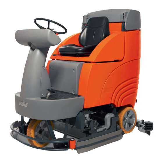
- Page 1 Instruction Manual Hakomatic B 650 R (7090.50)
- Page 2 Introduction It is our desire that the excellent pro- perties of the Hakomatic B 650 R Please be advised explicitly that should justify the confidence you de- we cannot accept any legal monstrated by making this purchase. claims out of the contents of this We did our best to supply you with an manual.
-
Page 3: Introduction
Modifications made to the modification of the machine. Hakomatic B 650 R in absence of the Moreover, any claim for warranty beco- manufacturer's consent will relieve the mes extinct if damages at the machine... -
Page 4: Table Of Contents
3.1.3 Control and brake pedals 3.1.4 Display elements 12/14 Accessory kit 3.1.5 Service display Technical date 27/29 Service display Taking into operation Working with the Hakomatic B 650 R 17 Detergents Driving with the Hakomatic B 650 R 17 5.3.1 Starting... -
Page 5: General Safty Instraction
The warning and instruction plates at- the unit or his authorized representati- and has to pay attention to other per- tached to the Hakomatic B 650 R give ve and who have been ordered expli- sons, in particular to children. -
Page 6: General Safety Instructions
The machine must not be used in safety standards are concerned. The machine is splash-water proof areas endangered by explosion The Hakomatic B 650 R has to be (IPX3) hazard. checked for its proper and safe opera- Do not allow water to get into the... -
Page 7: Battery Systems
2. Battery systems Battery charge warning unit Battery system A: 7450.02 (low discharge sensor) Tray-type battery, 24V/320Ah5, PzS, Aquamatic The Hakomatic B 760 R is equipped with a charge status monitoring device Battery system B: to preclude poor battery charge condi- Tray-type battery, 24V/280Ah5, PzS, maintenance-free 7451 tions. - Page 8 Socket and Grey for fluid-filled batteries manufacturer. Hako cannot be held lia- plug only with the same nominal Green for maintenance-free Gel batte- ble for damages resulting from the fact voltage.
- Page 9 2. Battery systems Coding system in the charger unit for fluid-filled and dry batteries Gel batteries) Example 24V...
-
Page 10: Changing Batteries
2. Battery systems Disassembling tray-type batteries 2.1 Changing batteries Switch off key switch 2.1.1 Tray-type batteries Remove control key Engage parking brake of the machine Tilt seat console (I/1) upwards. Jam strap (I/2) at position (I/4) Disconnect battery plug (I/11). Loosen hexagonal nuts (I/5) Remove holder (I/6) with battery cable and let it overhang at... -
Page 11: Compound Batteries
2. Battery systems Assembling tray-type batteries 2.1.2 Compound batteries Proceed in inverse order for assembly Disassembling compound batteries of tray-type batteries and note the fol- Remove or place the compound batte- lowing: Switch off key switch ries by means of a lifting device only. Remove control key Fasten plate (Fig. -
Page 12: Description
3. Description 3.1. Control and display 3.1.1 Left-hand control panel 3.1.2 Right-hand control panel elements Adjust driver's seat A Key switch (on/off) Adjust the driver's seat such that the operator is comfortably seated and has B Horn button all control elements within his reach. E Pilot lamp (red) for max. -
Page 13: Control And Brake Pedals
3. Description H Hourmeter/service display S Switch position for working flood- 3.1.3 Control and brake pedals light; when equipped with warning- I Pilot lamp for battery charge condi- flasher option, this switch position- tion initiates flashing of the warninglight. L Key for brush drive with pilot lamp T When equipped with warning flas- (green) her option, this switch position initia-... -
Page 14: Display Elements
3. Description 3.1.4 Display elements C Direction selector E Pilot lamp (forward/reverse) (red) for max. filling level selects the travel drive di- in soiled water tank A Key switch rection. alights if the max. filling (on/off) turns the electri- level is attained in the so- cal system ON/OFF and Forward switch position = forward ride iled water tank. - Page 15 3. Description H Hourmeter/service A flashing red light indicates that ope- display ration will soon be interrupted and a displays the operation buzzer sounds. hours. The meter only counts if the consumers L Key for brush drive such as drive or brush motor or suction with pilot lamp (green) turbine are ON.
- Page 16 3. Description S Working floodlight- N Key for water flow re- P Key for water flow position duction with pilot lamp raising with pilot lamp (green) (green) In this position of switch D (Fig. 3) the working is used to reduce the wa- is used to increase the floodlight is on.
-
Page 17: Service Display
If these measures do not help, note down the displayed error code and Note: If an error is present, a buzzer inform your local Hako centre. sounds and the red lamp lights (-) - the operating hours displayed, e.g. During operation, the dot flashes. -
Page 18: Service Display
4. Service display Displayed Malfunction Cause Remedy error code qCord or similar matter qRemove cord or other matter Brushes stop 1. 2. 5. 2. accumulated between brush and shaft qRubber protection from the brush qAdjust rubber protection head loosened and slipped under and fasten (ground clerance the brush 2 to 3 mm) -
Page 19: Taking Into Operation
5.1 Working with the Before starting to work, check the Test made by yourself in practise will Hakomatic B 650 R and its working help you find the ideal type of deter- Hakomatic B 650 R implements for their proper and safe... -
Page 20: Stopping 18
Lift the brush head before opening, slots, on electronic modules, Actuate the following control riding over obstacles (doorsteps) of control panels or sealing. elements for operation of the 10mm height. Hakomatic B 650 R Switch key switch ON Release parking brake (if actuated) -
Page 21: Soiled Water And Fresh Wter Tanks
5. Taking into operation 5.4 Soiled water and fresh 8 Maintenance opening Note: Empty and rinse the soiled 9 Level measuring, water tank after work. Clean the floater water tanks fresh water tank as well. 10 Inlet openings of fresh water tank Clean the drain hose plug at regular intervals and grease the O-ring if required. -
Page 22: Plate Brush Head
5. Taking into operation 5.5 Plate brush head Lower plate brush head Switch off by key switch and remo- ve key Engage parking brake Disconnect battery plug (open seat hood) 5.5.1 Dismounting plate brush head Locking hook (VII/1) unhook, right-hand separator, complete lowers itself on the soil Loosen hex. -
Page 23: Mounting Plate Brush Head
5. Taking into operation Check whether all hooks have snap- ped in by rotating the brush. 5.5.2 Mounting plate brush head Mount plate brush head according to Fig. VIII Connect water hose (VIII/2) and solenoid valve 5.5.4 Dismounting plate brushes Connect electric lines and brush motor Lift out the brush head and switch off... -
Page 24: Squeegee
5. Take into operation 5.6 Squeegee 5.6.1 Cleaning the Squeegee 5.6.2 Changing the Sealing Strips Check the squeegee (Fig. 1/1) daily Check the inner and outer sealing 1 Squeegee and clean as necessary. strips on the squeegee (Fig. 1/1) wee- 2 Star-shaped knob To clean it lift the squeegee out, pull off kly for signs of wear. -
Page 25: Adjusting The Sealing Strips
5. Take into operation 5.6.3 Adjusting the Sealing Strips Angle Adjustment The angle adjustment is the decisive factor in ensuring that the sealing strips on the squeegee lie evenly on the floor. 1. Park the machine on a level surface and lower the squeegee. -
Page 26: Height Adjustment
5. Take into operation 5.6.4 Height Adjustment The height adjustment is set to 3 mm at the factory. If streaks are produced, despite an optimum angle adjustment, the clearance between the rollers and floor must be adjusted by changing the number of washers on the holder. - Page 27 5. Take into operation...
-
Page 28: Accessory Kit
6. Accessory kit Brushes and Pads The Hakomatic B 650 R should be Only use brush and pad types indica- equipped with brushes/pads from the ted above. Using other brush/pad accessory kit as required by the types may affect your safety. -
Page 29: Technical Date
7. Technical data Dimensions Length with squeegee 76/86,5 Width w/o squeegee Height above tank lid top Working width Brush head 86,5 Squeegee Weights Empty weight (without batteries) Total weight (operable) Performance data Driving speed Km/h 7.0/3.4 forward/reverse up to max. Gradability, (tank filled) Ramp angle (level/inclined) Degree... - Page 30 7. Technical data Tank capacities Fresh water tank Soiled water tank Brush head Piece(s) Quantity of brushes /min Brush speed Brush pressure N/cm 0,34 Specific surface pressure Suction system Air volume mbar Vacuum Electric system Operating voltage 2500 Wattage max. (P1) DIN EN 60335-2-72 Protection class Brush motor (P1)
- Page 31 7. Technical data Noise level dB (A) Sound pressure as per DIN EN ISO 11201, part 1 under nor- mal conditions of use measured at the operating area Vibrations The frequency weighted acceleration which has an effect upon the upper limbs (hand-arm-system) measured accor- ding to EN 1033 under normal condition does not exceed The frequency weighted acceleration which has an effect upon the body (feet and back) measured according to EN...
-
Page 32: Maintenance And Service
Please contact your local Hako service parts, switch motors off. centre; your Hako dealer there will be If the machine is battery-driven, glad to perform the work for you. The disconnect the battery plug. - Page 33 For safety reasons, use exclusively ge- The Hakomatic B 650 R is equipped nuine spare parts. with a service display. If a malfunction occurs during operation, e.g. a defecti-...
-
Page 34: Maintainance Table
8. Maintenance and service The daily and weekly maintenance intervals are to be performed by the customer. The 250th, 500th und 1000th maintenance intervals are to be performed by authorized Hako-Service workshop. Interval 8.2 Maintenance Table daily and weekly in addition... - Page 35 8. Maintenance and service Maintenance interval 8.2 Maintenance Table Drive battery: check electrolyte and acid level and voltage Brake: check function of brake pedal and parking brake Steering: lubricate gear and check play Tank: check clear water tank, clear water supply, soiled water tank and drain hoses. Replace O- rings of the drain hoses Tank lid: check lid sealing and replace sieve if required Extraction: check suction hose for tight fitting or damages, check low pressure at suction hose...
- Page 36 8. Maintenance and service Maintenance interval 8.2 Maintenance Table All maintenance work acc. to maintenance interval 250 Read out error memory Wheel drive: check wheel bolts (34 Nm) Brake pedal: check brake pad and brake disc Electric power test: check forward/reverse wheel drive motor, check suction turbine and check left/right plate brush drive Clindrical broom drive: check toothed belt and replace if required Optical condition of the machine: colour, corrosion, check nameplates/labels...
- Page 37 8. Maintenance and service Maintenance interval 8.2 Maintenance Table 1000 All maintenance work acc. to maintenance interval 500 Travel drive motor: replace carbon brushes Cylindrical broom drive: replace toothed belt Optical condition of the machine: colour, corrosion, check nameplates/labels Trial ride: check functional and safety-relevant components...
-
Page 38: Greasing Joints At The Squeegee Holder
8. Maintenance and service 8.3 Greasing joints at the squeegee 8.4. Greasing the gear ring of the 8.5 Cleaning and replacing the holder wheel drive and the steering water filter for fresh water pinion supply of brushes VIII Fresh water filter Lateral view of the squeegee holder Front view of the machine Clean or replace the water filter (XV/1) -
Page 39: How To Mount The Stabilizer
8. Maintenance and service 8.6 Tank stabilizer How to mount the stabilizer Before fitting plate to measure X at the stbilizer, pre-mount to 20 mm Mount complete stabilizer (XVI/6) in the tank and fasten hand-tight by means of (XVI/1 and 2) Fasten plate (XVI/5) hand-tight at tank wall and determine X Adjust tension of plate (XVI/5) -
Page 40: Ec Declaration Of Conformity
(have) been that the product respected: EN 292 Hakomatic B 650 R EN 60335-2-72 Type: 7090 EN 55081-1 EN 50082-1 to which this declaration relates corres- ponds to the relevant basic safety and... - Page 42 Spitzentechnik für eine saubere und schönere Umwelt Superior technology for a cleaner and better environment Hako-Werke GmbH · Stammwerk und Hauptverwaltung · Headquarter Hamburger Str. 209-239 · D-23843 Bad Oldesloe · ¤ (0 45 31) 806-0 · Fax (0 45 31) 806-338...
Need help?
Do you have a question about the Hakomatic B 650 R and is the answer not in the manual?
Questions and answers