HAKO Scrubmaster B175 R Series Manual
Hide thumbs
Also See for Scrubmaster B175 R Series:
- Operating manual (102 pages) ,
- Quick start manual (2 pages)
Table of Contents
Advertisement
Quick Links
Service-Handbuch
Service Booklet
Scrubmaster B 175 R
(7180.XX)
Schulung/Training
Fehlersuche/Troubleshooting
Einstelldaten/Adjustments
.
.
.
Hako GmbH
Technisches Produktmanagement
D-23840 Bad Oldesloe
Updated 03/2019 - Rev.1.03
Confidential - For internal use only!
.
Vertraulich – nur für den internen Gebrauch
Sheet 1
Advertisement
Table of Contents

Subscribe to Our Youtube Channel
Related Manuals for HAKO Scrubmaster B175 R Series


Summary of Contents for HAKO Scrubmaster B175 R Series
- Page 1 Service-Handbuch Service Booklet Scrubmaster B 175 R (7180.XX) Schulung/Training Fehlersuche/Troubleshooting Einstelldaten/Adjustments Hako GmbH Technisches Produktmanagement D-23840 Bad Oldesloe Updated 03/2019 - Rev.1.03 Confidential - For internal use only! Vertraulich – nur für den internen Gebrauch Sheet 1...
-
Page 2: Table Of Contents
Table of contents Information General information 2.1 Settings 2.1.1 Control panel 2.1.2 Machine control unit 2.2 Brief description 2.2.1 Switching off suction / waste water tank full 2.2.2 Solution tank display 2.2.3 Machine home position 2.2.4 Seat contact switch (3.6.6.4.) 2.3 Diagnostics and communications 2.3.1 Prerequisites 2.3.2 Diagnostic software on the diagnostic computer... - Page 3 2.4.7 Deleting the last error on the display panel 2.4.8 Deleting error entries Technical data Maintenance intervals 4.1 Hako system maintenance (customer) 4.2 Hako system maintenance I 4.3 Hako system maintenance II 4.4 Hako system maintenance S Cleaning programmes (FPV)
- Page 4 Table of contents Machine settings 6.1 Basic settings 6.1.1 Cleaning units 6.1.2 Battery and charger settings 6.1.3 Battery setting (LDS) 6.1.4 Charger 6.1.5 Charger characteristic curves 6.1.6 Charging data table of the integrated charger 6.1.7 All-wheel drive variant – X-AC 6.1.8 SD storage medium in control panel 6.2 Customer-specific settings (PPV) Mechanical components...
- Page 5 Table of contents Water pump 8.1 Water quantities 8.2 Water pump standstill detection Drive 9.1 DMC drive control unit (front) 9.1.1 Connection description - drive control unit (front) 9.1.2 Service codes - drive control unit (front) 9.1.3 Brake - manual release of the brake (front) 9.1.4 Brake –...
- Page 6 Table of contents Service messages 10.1 Meaning of different switch on displays 10.2 Service alarm clock 3.3.1.1 Battery charger 11.1 Operating manual 11.2 Programming the charger Options Notes Sheet 6...
-
Page 7: Information
1. Information Caution: • During all work at the machine, secure it against unintentional movement. • Only carry out work at the machine when it has been de-energised (disconnect the battery plug), except for current and voltage measurements. • After repairing electrical drives, measure the starting and operating currents to detect possibly still present errors. -
Page 8: General Information
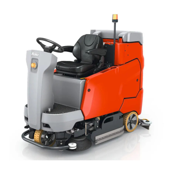
2. General information The Scrubmaster B175 R is equipped with a multifunction display on which all machine statuses are displayed and machine settings can be made. If a fault occurs, the wrench in the display lights up and the machine beeps. The current service code (four-digit alphanumerical code in the service indicator) is shown with flashing dots between the characters. - Page 9 2. General information Scrubmaster B175 R The Scrubmaster B175 R is available in working widths of between 85 cm (cylindrical brush) as well as 90 cm and 108 cm (plate brush). The machines are delivered from the factory with batteries as standard; here it is possible to choose between a maintenance-free 36V/280Ah PzV trough battery and a 36V/320Ah PzS trough battery.
- Page 10 2. General information Configuration machines are manufactured order-specifically according to customer wishes from a pool of available equipment features. Additional options (chemical dosing, working light, warning signal, etc.) are installed in the factory. For more details, see the relevant current price lists. Sheet 10...
-
Page 11: Settings
2.1 Settings Respective settings can be carried out via the machine’s configuration menu. Currently, these settings are carried out via the machine display. There are settings which can also be carried out by the operator without restrictions (e.g. cleaning programmes in Chapter 3 and several settings in Chapter 2). This is always possible if a diskette is displayed next to the value (Chapter-Configuration-Content). -
Page 12: Control Panel
A micro-SD card with the required image file can be written to using the Hako diagnostics. If the micro SD card is missing or the image file on the card is defective or missing, the control panel will only show a “blue screen”. -
Page 13: Machine Control Unit
Therefore, the machine software must be “flashed” onto the central control unit after mechanical installation and electrical connection of the central control unit. • Service PC on which the current Hako diagnostic software is installed. (Windows 7 or higher) •... -
Page 14: Brief Description
2.2 Brief description Machine control takes place with the following electronics: • Central electronics (A01) • Control and display panel (A02) (MFD) • Drive control unit (A04) / All-wheel-drive-option — 2. Drive control unit (A05) • Chemical dosing (A101) • Side brush control (A07) The control electronics (A01) assumes all control and monitoring tasks in the machine except for the drive functions. -
Page 15: Switching Off Suction / Waste Water Tank Full
2.2 Brief description 2.2.1 Switching off suction / waste water tank full Suction is switched off by the operator via the tip switch or automatically in case of the signal “waste water tank full” to protect the suction turbine. Switching off by the operator: •... -
Page 16: Solution Tank Display
2.2 Brief description 2.2.2 Solution tank display The machine has a fill level indicator for the fresh water tank in the MFD which displays the current fill level in steps of 20%. The fill level is measured via a differential pressure sensor. The pressure sensor is connected to an immersion tube via a hose which is located next to the water filling opening of the fresh water tank. -
Page 17: Machine Home Position
2.2 Brief description 2.2.3 Machine home position After switching on the machine, all components are set to “home position” provided that the seat contact switch is actuated (closed). The lifting elements will lift unless they have been switched off via the micro-switch for the upper end position integrated in the lifting element (squeegee) or the upper end position is detected by the control unit via the integrated potentiometer. -
Page 18: Seat Contact Switch (3.6.6.4.)
2.2 Brief description 2.2.4 Seat contact switch (3.6.6.4.) The seat contact switch (S05) is connected to the control electronics A1 at A1:X15.6+18 and A1:X15.7+19. The control electronics (A1) responds to the relief of the seat with an approx. 2 second delay. - Page 19 2.2 Brief description To reactivate the machine after triggering “seat switch manipulation”, the machine control unit must “register” the change of the switch status or the change between ‘operator is sitting on the machine’ and ‘operator has left the seat’. To achieve this, the seat contact switch must be opened and closed several times while the machine is on.
-
Page 20: Diagnostics And Communications
2.3.1 Prerequisites The following components are required to activate the control unit of the Scrubmaster B175 R after a replacement: • Current Hako diagnostic software (via the Hako WebX download portal) • Service PC (e.g. Panasonic CF19 / CF20) •... -
Page 21: Diagnostic Software On The Diagnostic Computer
Information on accessing the download server can be requested from Maike Christiansen, e-mail: mchristiansen@hako.com. To install the software on a service computer or for software updates: Follow the steps in the “Instructions” for Hako diagnostics setup which is supplied with the diagnostic software. Sheet 21... -
Page 22: Connecting To The Diagnostic Pc
2.3 Diagnostics and communication 2.3.3 Connection to the diagnostic PC • Ensure that the –A01 control unit has been fully installed in the machine before activating the backup battery. To do this, remove the insulating strip between the battery (CR2032) and the battery holder on the control unit. •... - Page 23 2.3 Diagnostics and communication With CAN-FOX interface PN 03502430 (*): (recommended variant – see Chapter 2.1.3) Connect the D-Sub 9 connection of the diagnostic cable marked CAN1 (red marking) to the D-Sub 9 connection of the interface marked “CAN”. Caution: Do not use the D-Sub 9 connection with the designation RS232.
-
Page 24: Connection Scheme With The Diagnostic Pc
2.3 Diagnostics and communication 2.3.4 Diagram for connection between machine and the diagnostic PC OBDII Cable D-Sub9-Connector PN 03502750 „RS232“ CAN-Fox Interface PN 03502430 * D-Sub9-Socket OBD connector, „CAN2“ - BLACK to machine USB-connector, D-Sub9-connector D-Sub9-Socket „CAN“ „CAN1“ - RED to Service PC Sheet 24... -
Page 25: Flashing The Software
2.3 Diagnostics and communication 2.3.5 Flashing the software: Turn on the machine. Start the Hako diagnostic software. Select the “HAKO” button, then click the “Scrubmaster B175 R” button. The application independently searches for a new, blank control unit. Follow the instructions of the programme. Do not turn off the machine or disconnect the connection before flashing has been completed. -
Page 26: Configuration Menu
Configuration Menu 2.4.1 Entering the configuration Menu The turn-push knob can be used to access sub-menus in which it is possible to -set machine configurations -set the clock -delete the last error in the display and the error overview Select the sub-menus: In the main display screen, use the turn-push knob to select the red button with the green arrow and actuate it by pressing the turn-push knob. - Page 27 Configuration Menu “Return” key / Turn-push knob “Menu selection” softkey for selecting the sub-menus. The sub-menu of the operating hours appears and the select buttons are displayed on the left-hand side (with yellow border for selection). Sheet 27...
- Page 28 Configuration Menu Go back to the main menu using • the return key on the keypad • the home button (softkey) on the display panel “Menu selection” softkey for selecting the sub-menus. The sub-menu of the operating hours appears and the select buttons are displayed on the left-hand side (with yellow border for selection).
-
Page 29: Time And Date Setting Menu
Configuration Menu 2.4.2 Time and date setting menu Respective times and dates can be set in the time/date setting sub-menu. Time selection 12 h / 24 h in hours/minutes, Date in day/month/year Turn the turn-push knob to the adjustable parameters and press. If the border turns green, the parameter can be adjusted. -
Page 30: Configuration Setting Menu
Configuration Menu 2.4.3 Configuration setting menu Respective options and values can be adjusted in the system settings sub-menu “configuration menu”. Adjustable values are divided into operator settings (can be changed by the operator), service settings (can only be changed by service staff using a password, diagnostics plug PN 03006790 or diagnostics device), and non-adjustable values (can only be changed via a software update). - Page 31 Configuration Menu Connect the diagnostics plug PN Use the return key on the 03006790 to –A01/X20 to change the keypad to go back without protected parameters. saving the currently selected value. Menu operation: Turn the turn-push knob to access the field of the value to be changed.
-
Page 32: Settings, That Can Be Carried Out Without Code
Configuration Menu 2.4.4 Settings that can be carried out without code or diagnostics plug Settings that can be carried out by the operator are indicated by not having to enter a code in the top field (or connecting a diagnostics plug) and by the disk displayed next to the configuration setting for saving. Without a code, all settings can be viewed but only released ones can be adjusted. -
Page 33: Settings, That Can Only Be Carried Out With Code
To avoid having to enter a code, it is also possible to use the diagnostics plug PN 03006790 at connection – A01.X20 of the control unit. The code is assigned by the HAKO Service during production at the assembly line or when installing a new control unit. The code is calculated from the running sequence number of the machine plus 1. -
Page 34: Resetting The Last Error And Deleting The Error Memory
Configuration Menu 2.4.6 Resetting the last error and deleting the error memory The last ten errors can be displayed with real time and date in the error information sub-menu. The last error can be deleted in the main display. ... -
Page 35: Deleting The Last Error On The Display Panel
Configuration Menu 2.4.7 Deleting the last error on the display panel Use the cursor to navigate to “DEL” between time / date and the error message of the last occurred error (“DEL” is only visible if the error has been reset, i.e. the service key has extinguished). ... -
Page 36: Deleting Error Entries
2.4.8 Deleting error entries The entries in the display (not the diagnostics memory) can only be deleted via the HAKO diagnostics system. New error entries are saved chronologically (the last occurred error is displayed at the top position). -
Page 37: Technical Data
Technical Data Sheet 37... - Page 38 Technical Data Sheet 38...
- Page 39 Technical Data Sheet 39...
- Page 40 Technical Data Sheet 40...
- Page 41 Technical Data Sheet 41...
- Page 42 Technical Data Sheet 42...
- Page 43 Technical Data Sheet 43...
- Page 44 Technical Data Sheet 44...
-
Page 45: Maintenance Intervals
Parts to be replaced for the individual maintenance tasks are determined. Hako system maintenance: • Assures the reliable readiness for use of the Hako cleaning machines (preventive maintenance). • Minimises operating costs, repair costs, costs for maintenance. -
Page 46: Hako System Maintenance (Customer)
4.1 Hako-System Maintenance (customer) Sheet 46... - Page 47 4.1 Hako-System Maintenance (customer) Sheet 47...
-
Page 48: Hako System Maintenance I
4.2 Hako-System Maintenance I Sheet 48... - Page 49 4.2 Hako-System Maintenance I Sheet 49...
- Page 50 4.2 Hako-System Maintenance I Sheet 50...
-
Page 51: Hako System Maintenance
4.3 Hako-System Maintenance II Sheet 51... -
Page 52: Hako System Maintenance S
4.4 Hako-System Maintenance III/S (Safety Check) Sheet 52... - Page 53 Cleaning Programs (FPV) The cleaning programmes are used to control the behaviour of the water supply to the brushes, the brush motors with regard to the position of the driving direction switch and the speed control potentiometer (forwards, neutral, reverse) as well as the squeegee.
- Page 54 5. Cleaning Programs (FPV) Function Content Brush off when drive control is in neutral Brush off when drive control is in reverse Lift brush when drive control is in neutral Lift brush when drive control is in reverse Water off when drive control is in neutral Water off when drive control is in reverse Lift squeegee when drive control is in neutral Lift squeegee when drive control is in reverse...
- Page 55 5. Cleaning Programs (FPV) Description Adjusted FPV Refer to FPV table Refer to FPV table Refer to FPV table Refer to FPV table Refer to FPV table Refer to FPV table Refer to FPV table Refer to FPV table Refer to FPV table Table 5.2 Sheet 55...
-
Page 56: Machine Settings
6. Machine settings 6.1 Basic settings The machine series Scrubmaster B175 R offers different equipment options and working widths. These can be set and adapted in the configuration menu. To check and change the setting, access the configuration menu as described in Chapter 2.4. -
Page 57: Cleaning Units
6. Machine settings 6.1 Basic settings 6.1.1 Cleaning units 3 different brush units are used with the Scrubmaster B175 R. Two plate brush units with a working width of 90 cm or 108 cm, and a cylindrical brush unit with a working width of 85 cm. This setting is necessary for correct functioning of the overrange limits and water quantities. - Page 58 6. Machine settings 6.1.1 Cleaning units Description Brush decks Plate brush deck 900mm Cylindrical brush deck 850mm Plate brush deck 1080mm Table 6.1 Sheet 58...
-
Page 59: Battery And Charger Settings
6. Machine settings 6.1.2 Battery and charger settings In order to achieve optimum service life and performance of the batteries available for the machine, it is necessary to set the battery monitor, called LDS, and the charger to the correct battery type and capacity. These settings are carried out in the menu items 0.3.X;... -
Page 60: Battery Setting (Lds)
6. Machine settings 6.1.3 Battery settings (LDS) PzS and PzV are batteries with tubular type plates. GiV and Pzv are encapsulated, completely maintenance-free gel batteries. PzS are sealed, low-maintenance batteries containing liquid electrolyte. Regular checking of the electrolyte as well as topping up with distilled water are required here. - Page 61 6. Machine settings 6.1.3 Battery settings (LDS) Description LDS Adjustment - Battery-Type (only for 0.4.0; 0.4.1 and 0.4.2) Crown w/o Offset Crown GIS, „Foreign“ PzS or PzB „Foreign“ PzS or PzB AGM - only for Hoppecke batteries Table 6.2 Sheet 61...
-
Page 62: Charger
6. Machine settings 6.1.4 Battery Charger In this menu item (0.4.X), it is specified whether the machine features an integrated charger and whether this charger communicates with the machine control unit via CAN bus. With chargers that communicate with the machine, there are various selection options. If the charger with a free characteristic curve selection is selected, the correct characteristic curve must be determined using the charger documents and then set correctly under 0.5.X. - Page 63 6. Machine settings 6.1.4 Battery Charger Description Battery charger and Battery types w/o battery charger battery charger w/o communication Battery charger with communication (manual charging characteristics selection) Battery charger with communication for PzV-batteries Battery charger with communication for PzS/PzB-batteries Table 6.3 Sheet 63...
-
Page 64: Charger Characteristic Curves
6. Machine settings 6.1.5 Charging Characteristics Description Charging characteristic / Battery size for 0.4.2 for 0.4.6 for 0.4.7 320Ah PzS 280Ah PzV Automatic LDS setting Table 6.4 Sheet 64... -
Page 65: Charging Data Table Of The Integrated Charger
6. Machine settings 6.1.6 Charging characteristics for integrated charger Sheet 65... -
Page 66: All-Wheel Drive Variant - X-Ac
6. Machine settings 6.1.7 Variant All wheel drive (A XC) The all-wheel drive variant must be activated here if it is present in the machine. Description All wheel drive installed only Front wheel drive Front- and Rear wheel drive Table 6.6 Sheet 66... -
Page 67: Sd Storage Medium In Control Panel
6. Machine Adjustments 6.1.8 SD-storage medium in dash board This parameter must not be adjusted. Can currently lead to a complete failure of the machine. A missing SD-card in the dash board, leads to a “Blue-Screen” , that only displays the clock and the software version of the machine control system. -
Page 68: Customer-Specific Settings (Ppv)
6. Machine settings 6.2 Customer-specific settings (PPV) Different settings can be carried out at the machine using the programmable programme variants. It can, e.g., be set whether the last error that occurred in the machine is shown when turning on the machine or not. Check and change the setting as described in Chapter 2.4 Configuration. - Page 69 6. Machine settings 6.2 Customer-specific settings (PPV) Description Last error indication after switching on machine Deactivate Activate Water level when switching on scrubbing Last stage set Preset level (4) Water level when switching on TOOL (menu option only appears when TOOL option is activated!) Last stage set Preset level (4)
- Page 70 6. Machine settings 6.2 Customer-specific settings (PPV) Description BlueSpot always On (drive pedal neutral) Deactivate Activate Silence Mode Setting Is not saved Is saved Acoustic Alarm Tone Interval (menu option only appears when the Acoustic Alarm option is activated!) Standard Alternative Highest water stage independent from machine speed Table 6.9...
-
Page 71: Mechanical Components
7. Mechanical components 7.1 Squeegee Squeegee connection Installation note: 1. Hook squeegee connection into chassis. 2. Align parallel to floor and tighten bolts. Squeegee connection default setting: 1. For default setting of adjusting bushing see figure 7.1 (dimensions 9 and 8 mm). 2. - Page 72 7. Mechanical components 7.1 Squeegee Squeegee connection Adjusting bushing 9 +-1 mm 8 +-1 mm Fork head Base plate Figure 7.1 Sheet 72...
- Page 73 7. Mechanical components 7.1 Squeegee Adjusting the sealing strips / inclination The correct inclination adjustment is decisive for: • ensuring that the sealing strips of the squeegee are lying evenly on the ground over their contact surface • ensuring that the squeegee runs quietly and evenly during the suction process. 1.Place the machine on a level surface and lower the squeegee using the squeegee key figure 7.2b -46.
- Page 74 7. Mechanical components 7.1 Squeegee Figure 7.2a Figure 7.2b Sheet 74...
- Page 75 7. Mechanical components 7.1 Squeegee Height adjustment The height adjustment (X) of the supporting rollers Fig. 7.4 has been set to 7 mm in the factory. If striping still occurs despite optimum inclination adjustment, readjust the distance between the supporting rollers and the lower edge of the sealing strip. 1.Place the machine on a level surface.
- Page 76 7. Mechanical components 7.1 Squeegee Height adjustment Figure 7.4 Sheet 76...
-
Page 77: Rotating Brush Heads
7. Mechanical components 7.2 Plate brush heads Plate brush heads in two working widths (90 cm and 108 cm) are used with the Scrubmaster B175 R. Both brushes are driven by a separate motor. The left and right brushes on the plate brush unit both rotate clockwise. This is needed for automatic brush decoupling and automatic threading. -
Page 78: Roller Brush Heads
7. Mechanical components 7.3 Cylindrical brush heads A deck with a working width of 85 cm is used as the cylindrical brush unit for the Scrubmaster B175 R. The cylindrical brush unit can also be extended with a side broom unit. Use the guide rail to adjust the dirt hopper ensuring the brush strip is positioned all-round on the housing and the dirt hopper can still be slightly inserted. -
Page 79: Lifting Element Brush Head
7. Mechanical components 7.4 Brush head lifting 7.4.1 Potentiometer in the lifting element for the brush head The lifting element for the brush head features integrated position detection. The position detection is supplied with 24V via the machine control unit A01.X13:1 (+) and A01.X13:7 (-). -
Page 80: Water Pump
8. Water pump The water pump for supplying the operative units is connected at the central control unit at A01.X12:1 + 11. It is operated via a clocked voltage to deliver different quantities of water for the stages. The voltage values measured here depend on numerous factors; it is therefore not possible to specify exact values. -
Page 81: Water Quantities
8. Water pump 8.1 Water quantities The water quantities in the 5 water stages for the three brush units are listed in the following table. Water quantities (l per min) Plate brush Plate brush Roller brush 900 mm 1080 mm 850 mm Stage 1 Stage 2... -
Page 82: Water Pump Standstill Detection
8. Water pump 8.2 Water pump standstill detection If the pump cannot delivery freely because the water cannot run freely through the hoses to the brush, so-called water pump standstill detection comes into effect. Automatic water pump standstill detection: The electronics offers the option to protect the water pump if the pump can no longer convey freely. -
Page 83: Drive
Drive The drive control features its own diagnostics and a self-test. Therefore, the function of the drive control unit is locked when turning on the machine if the speed control potentiometer isn´t in neutral or is not recognised as being in neutral position. The same behaviour applies after the seat contact switch has opened and is closed again. -
Page 84: Dmc Drive Control Unit (Front)
Drive 9.1 DMC drive control unit - Front The DMC drive control unit features a diagnostic input. Unless clearly noted in the service documents, changes to the preset values and parameters is generally not permitted. Currently, only the diagnostics with flash codes for the LED indicator is used. 9.1.1 Connection description: M1;... - Page 85 Drive 9.1.1 Connection description – drive control unit Front A1 – forwards (active when B- is connected) from A02:X109.3 A2 – reverse (active when B- is connected) from A02:X109.4 A3 – release for driving from speed control potentiometer switch B03 (active when B- is connected) A4 –...
-
Page 86: Service Codes - Drive Control Unit (Front)
Drive 9.1.2 Service codes DMC control unit -Front Code Error description Cause Remedy Warning - reduces the output, resets itself (if possible). Not used Low voltage Low battery voltage (<18 V) Charge the battery Not used High battery voltage (usually Extreme downwards travel (pay attention to High voltage during braking) (U>... - Page 87 Drive 9.1.2 Service codes DMC control unit - Front Code Name Description Remedy Drive error faults -Commences gracefull neutral brake - requires a neutral recycle action to reset fault Memory chip fault Memory not accessible Internal voltage <12V; replace Drive Control Unit Check the wiring of the direction switch 2 directions active forward and Reverse direction active...
- Page 88 Drive 9.1.2 Service codes DMC control unit - Front Code Name Description Remedy Soft error faults - immediately stops pulsing - Requires a neutral recycle action to reset fault Low voltage internal 12V supply too low Check charging level of the battery Not used Low voltage Battery voltage too low...
- Page 89 Drive 9.1.2 Service codes DMC control unit - Front Code Name Description Remedy Hard Error Faults - Immediately stops pulsing and open line contactor - Cannot be reset (only by a key switch recycle) Hardware over current trip Motor Over current Check Motor and Motor wiring Coil of Line Contactor or Magnetic Brake Contactor Coil driver fault...
- Page 90 Drive 9.1.2 Service codes DMC control unit - Front Code Name Description Remedy Hard Error Faults - Immediately stops pulsing and open line contactor - Cannot be reset (only by a key switch recycle) Not used Mosfet shortcircuited to battery minus Check insulating of the motor.
- Page 91 Drive 9.1.2 Service codes DMC control unit - Front Code Name Description Remedy Hard Error Faults - Immediately stops pulsing and open line contactor - Cannot be reset (only by a key switch recycle) CAN Error Front Only in 3WD Check CAN-Bus connection between front and rear 29 S01 CAN Fehler...
-
Page 92: Brake - Manual Release Of The Brake (Front)
Drive Brake – manual release of the brake - Front 9.1.3 In order to also move the machine without a power supply (no battery installed or other drive problems), the magnetic brake can be released manually. In order to push the machine, carry out the following steps: 1. -
Page 93: Brake - Testing The Brake Function
Drive Brake – testing the brake function 9.1.4 The brake must be capable of stopping the machine on a level road within 0.19 m per km/h. At a maximum speed of 8 km/h, this means that the maximum braking distance must not exceed 1.52 m. -
Page 94: Dmc Drive Control Unit (Rear)
Drive 9.2 DMC drive control unit - Rear The communication between the drive control unit Front (-A04) and the drive control unit Rear (-A05), is only via CAN-Bus. The two drive control unit have different parameter sets, Therefore the never have to be exchanged. 9.2.1 Connection description: M1;... - Page 95 Drive Connection description – drive control unit Rear 9.2.1 A1 – not used A2 – not used A3 – not used A4 – release from machine control unit (seat contact) (active when B- is present) from A01/X13.11 A5 – not used A6 –...
-
Page 96: Service Codes - Drive Control Unit (Rear)
Drive 9.2.2 Service codes DMC control unit - Rear Code Name Description Remedy Controller warning faults - Reduces only performance - Fault will reset itself (if possible) Not used Low Voltage Low Battery voltage (U < 18V) Charge battery Not used High Voltage High Battery Voltage (typically during braking) (U >... - Page 97 Drive 9.2.2 Service codes DMC control unit - Rear Code Name Description Remedy Drive error faults -Commences gracefull neutral brake - requires a neutral recycle action to reset fault Memory chip fault Memory not accessible Internal voltage <12V; replace Drive Control Unit Check the wiring of the direction switch 2 directions active Forward and Reverse direction active...
- Page 98 Drive 9.2.2 Service codes DMC control unit - Rear Code Name Description Remedy Soft error faults - immediately stops pulsing - Requires a neutral recycle action to reset fault Low voltage internal 12V supply too low Check charging level of the battery Error from drive control front;...
- Page 99 Drive 9.2.2 Service codes DMC control unit - Rear Code Name Description Remedy Hard Error Faults - Immediately stops pulsing and open line contactor - Cannot be reset (only by a key switch recycle) Hardware over current trip Motor Over current Check Motor and Motor wiring Coil of Line Contactor or Magnetic Brake short Check Line contactor (-K03) and Magnetic Brake...
- Page 100 Drive 9.2.2 Service codes DMC control unit - Rear Code Name Description Remedy Hard Error Faults - Immediately stops pulsing and open line contactor - Cannot be reset (only by a key switch recycle) Not used Mosfet shortcircuited to battery Mosfet shortcircuited to battery minus before Line Check insulating of the motor.
-
Page 101: Brake At The Rear Axle
Drive 9.2.3 Brake at the Rear axle If the machine is equipped with the X-AC- Drive system, additionally the brake at the rear axle has to be unlocked. Lift the lever on the right side of the machine, next to the rear wheel, till it snaps into place (Figure 9.4 A). -
Page 102: Steering Angle Sensor
Drive 9.2.4 Steering angle sensor In All wheel drive mode, the speed of the rear axle has to be adapted to the steering angle of the front wheel drive. For this reason a rotary sensor is installed at the front wheel drive. After the sensor is replaced, the sensor may need accurate adjustment. - Page 103 Drive 9.2.4 Steering angle sensor Steps for adaption of the steering angle sensor (PN 01372660) to the drive motor (PN 01371270) Instruction Bring the front wheel to center position. Install the Bushing pos. 100 in the Flange plate. Put the shaft pos. 20 in the bushing pos. 100. Align the key grove of the shaft transverse to the driving direction.
- Page 104 Drive 9.2.4 Steering angle sensor Figure 9.5 Folie 104...
- Page 105 Drive 9.2.4 Steering angle sensor Parts List Description Kordel-No. Description 2 Amount Length Unit Base plate sensor Shaft Flange bushing Spur gear Screw M6x20 DIN 4762 Screw M6x16 DIN 7984 Washer 10.5 DIN 125 Washer 6.4 DIN 9021 Lock Washer 6 Feather key A 3x3x8 DIN 6885 Table 9.1 Folie 105...
-
Page 106: Service Messages
Service messages Service- Description Remedy Code Check current consumption of brush motor (-M03) and 1.2.5.1. Thermo switch brush motor 1 (left) wiring of the thermo switch Check current consumption of brush motor (-M04) and 1.2.5.2. Thermo switch brush motor 2 (right) wiring of the thermo switch Short circuit in the brushmotor (-M03) or in it´s wiring;... - Page 107 Service messages Service- Description Remedy Code 1.4.6.4. Blocking protection Suction motor 2 Short circuit in the suction motor (-M17) or in it´s wiring 1.5.5.1. Malfunction Filling sensor solution tank Sensor value out of it´s range; recalibrate the sensor Current consumption broom motor and wiring thermo switch 2.2.5.1.
- Page 108 Backup battery empty Replace backup battery; Type CR2032 3.3.1.1. Service intervall expired Reset the service intervall with the Hako diagnosis re format the SD-card with the diagnosis system, if error repeats, replace 3.3.1.5. SD-Card on the Display the SD-card with a new one 3.3.6.2.
- Page 109 Servicemeldungen Service- Description Remedy Code Drive motor 2 overheated See blinking code at the drive control unit; check the wiring of the drive 3.4.5.b. (Option 3-wheel drive) motor thermo switch. Is the machine used outside it´s specification? 3.6.6.4. Seat contact switch manipulation See chapter 2.2.3.
- Page 110 Service messages Service- Description Remedy Code 4.6.1.2. Internal malfunction of machine control unit Replace the control unit (-A01) 4.6.1.3. Malfunction of internal software Replace the control unit (-A01) Malfunction battey charger- charger related 5.8.7.1. See battery charger manual - Malfunction problems.
-
Page 111: Meaning Of Different Switch On Displays
Service messages 10.1 Meaning of different switch on displays 1.) Display at missing SD-Card iin Dash board (Blue-Screen with time and Servicecode) 2.) Display, when the operating system at the machine control system is missing, isn´t started or the CAN-connection between machine control unit and dash board is interrrupted. -
Page 112: Service Alarm Clock
10.2 Service alarm clock – 3.3.1.1 The service alarm clock is set via the Hako diagnostic system. Sheet 112... -
Page 113: Battery Charger
Battery charger 11.1 Operating manual Sheet 113... - Page 114 Battery charger 11.1 Operating manual Sheet 114...
- Page 115 Battery charger 11.1 Operating manual Sheet 115...
- Page 116 Battery charger 11.1 Operating manual Sheet 116...
-
Page 117: Programming The Charger
Battery charger 11.1 Programming the charger The integrated charger is adjusted and parametrised exclusively via the machine control unit. (See Chapter 6.1.4 and 6.1.5) Sheet 117... -
Page 118: Options
Options Both factory and field options are available for the Scrubmaster B175 R series. The factory options are only available for new machines ex factory. The field options can be retrofitted in the machines. The parameters for the options that require a release via the machine’s control system are specified in Table 12.1. - Page 119 Options To adjust and check these values, access the programming level as described in Chapter 2.4 and enable the options. The “silence kit” is the default setting in all machines, but can be deactivated. The mechanical installation of the field options, if necessary, is described in the supplied instructions for these field options.
- Page 120 Options Description Silence-Kit not available available Warning Signal (Optical and acoustical) not available available Chemical Dosing Agent not available available TOOL not available available Sheet 120...
- Page 121 Options Description Pre Sweep Unit not available available Working Headlight not available available Fleetrecorder not available available Side Broom not available available Sheet 121...
- Page 122 Options Description Second Suction Motor not available available Warning Beacon on Pole not available available TOOL - Spinkle Nozzle (for cleaning of the recovery tank) not available available BlueSpot not available available Sheet 122...
-
Page 123: Notes
13. Notes Sheet 123... - Page 124 13. Notes Sheet 124...
Need help?
Do you have a question about the Scrubmaster B175 R Series and is the answer not in the manual?
Questions and answers