Table of Contents
Advertisement
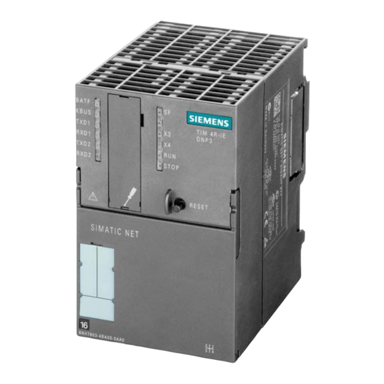
TIM DNP3
SIMATIC NET
Industrial Remote Communication -
Telecontrol
TIM DNP3
System Manual
TIM 3V-IE DNP3
TIM 4R-IE DNP3
12/2015
C79000-G8976-C253-04
___________________
Preface
Uses and properties of the
___________________
TIM
Network structures and
___________________
configurations
___________________
LEDs and connectors
Installation and
___________________
commissioning
___________________
Configuration in STEP 7
The SINAUT Configuration
___________________
Tool
___________________
Diagnostics and upkeep
___________________
Technical specifications
___________________
Approvals
___________________
Accessories
___________________
PG routing via WAN
1
2
3
4
5
6
7
8
9
A
B
Advertisement
Table of Contents


Need help?
Do you have a question about the SIMATIC TIM 3V-IE DNP3 and is the answer not in the manual?
Questions and answers